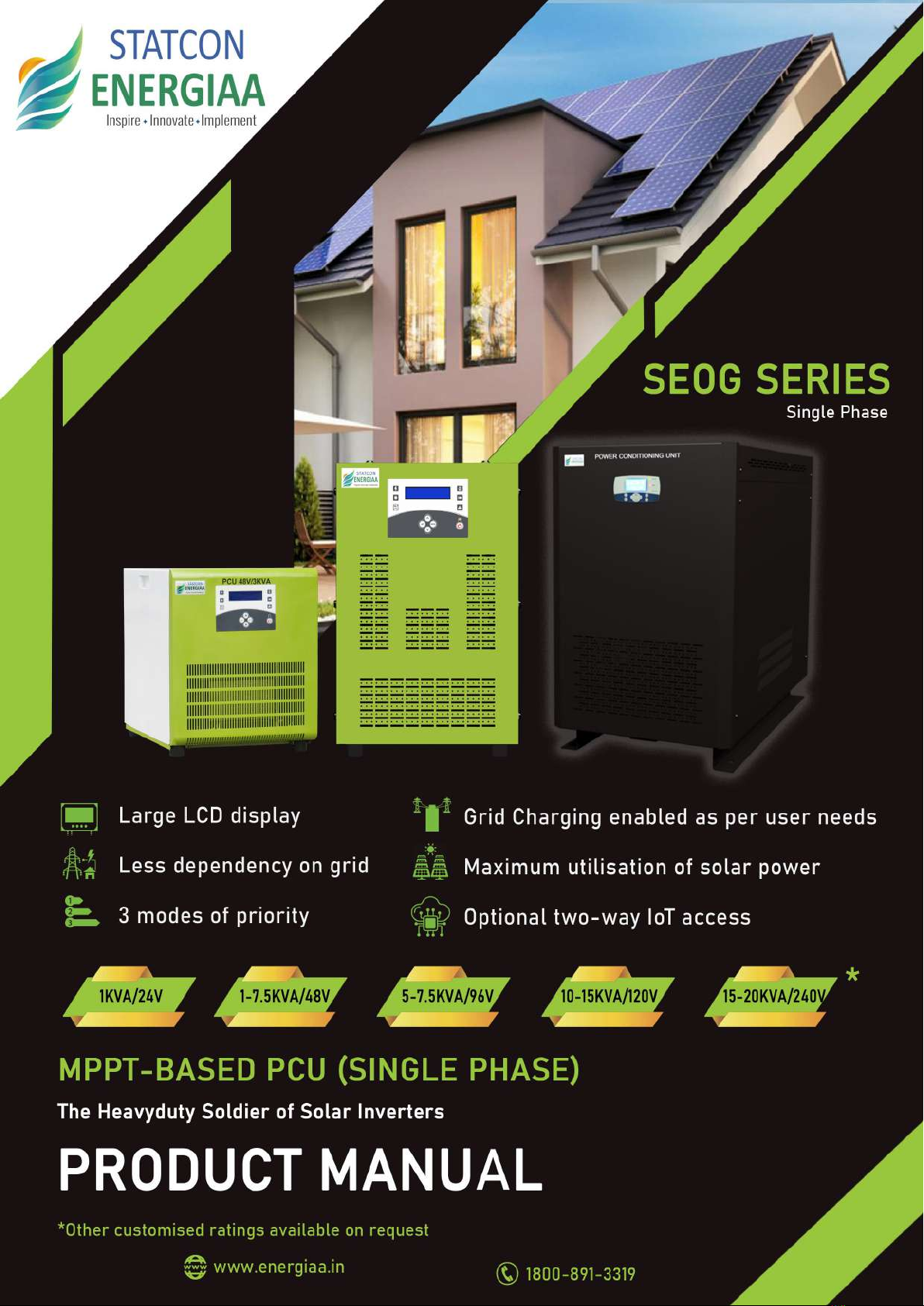
STATCON ENERGIAA SEOG Series User manual

1
1. NOTES ON THE MANUAL ...................................................................................................................3
1.1. SCOPE OF VALIDITY ......................................................................................................................................................3
1.2. SYMBOL INDICATIONS ................................................................................................................................................3
1.3. SAFETY ............................................................................................................................................................................4
2. INTRODUCTION .....................................................................................................................................5
2.1. PRODUCT DESCRIPTION ...........................................................................................................................................5
2.2. PRODUCT NOMENCLATURE FOR MPPT-Based MPPT PCU............................................................................. 5
2.3. PHYSICAL APPEARANCE & TERMINATION DETAILS OF INVERTER............................................................ 6
3. INSTALLATION ....................................................................................................................................10
3.1. LOCATION AND PLACEMENT ..................................................................................................................................10
3.2. ELECTRICAL WIRING .................................................................................................................................................12
3.3. ELECTRICAL CONNECTION .....................................................................................................................................13
3.2.1 CONNECTION TO THE BAT TERY ................................................................................................................................................................13
3.2.2 CONNECTION TO AC SUPPLY IN ..............................................................................................................................................................13
3.2.3 CONNECTION OF SOLAR MODULES (P V): SOLAR IN ..................................................................................................................13
3.2.4 CONNECTION OF LOAD: LOAD OUT .......................................................................................................................................................13
3.4 INSTRUCTION TO FOLLOW ........................................................................................................................................ 13
3.5 EARTHING ...................................................................................................................................................................... 14
3.6 STARTING UP THE PCU ............................................................................................................................................. 14
4. DISPLAY ................................................................................................................................................. 14
4.1 DISPLAY OVERVIEW ..................................................................................................................................................... 14
4.2 DISPLAY PARAMETERS .............................................................................................................................................. 14
4.3 MENU SETTINGS .......................................................................................................................................................... 15
4.4 LED INDICATIONS ........................................................................................................................................................ 16
4.5 MENU SETTING FLOW CHART .................................................................................................................................. 16
4.6 FAULT ANALYSIS ........................................................................................................................................................ 17
Contents
Copyright Declaration.........................................................................................................................................................2
2.4. FEATURES ..................................................................................................................................................................... 9

2
5.3 WORKING OF SYSTEM............... ................................................................................................................................ 20
5.2 LOAD CHART & BATTERY SIZING ........................................................................................................................... 19
6. MAINTENANCE & TROUBLESHOOTING ......................................................................................21
6.1 VISUAL INSPECTION........................ ........................................................................................................................... 21
6.1.1 CLEANING THE INVERTER EXTERNALLY ........................................................................................................... 21
6.1.2 BATTERY MAINTENANCE........................................................................................................................................ 21
6.1.3 PV MAINTENANCE......................................... ........................................................................................................... 21
6.2 TROUBLESHOOTING........................................ ........................................................................................................... 21
APPENDIX-1............................................................................................................................................. 24
GENERAL FAULTS AND THEIR SOLUTIONS... ........................................................................................................... 24
A. INVERTER OUTPUT VOLTAGE IS NOT AVAILABLE .......................................................................................... 24
B. SOLAR CHARGING IS NOT AVAILABLE............................................................................................................... 24
C. MAINS CHARGING IS NOT HAPPENING.............................................................................................................. 24
D. OUTPUT FLUCTUATION............................................................................................................................................. 24
APPENDIX-2............................................................................................................................................ 25
TECHNICAL SPECIFICATION -LOW VOLTAGE 1-8KVA............................................................................................. 25
APPENDIX-3............................................................................................................................................ 27
SERVICE AND CUSTOMER CARE................................................................................................................................... 27
Copyright Declaration
The copyright of this manual exclusively belongs to STATCON ENERGIAA PVT. LTD. Any corporation or individual
should not plagiarize, partially copy or fully copy (including software, etc.) it. Reproduction or distribution of it any
from or by any means is not permitted. All rights reserved. STATCON ENERGIAA PVT. LTD. reserves the right of
final interpretation. This document is subject to changes without prior notice. This is valid only for SEOG MPPT-
based PCUs and not for custom built ratings.
TECHNICAL SPECIFICATION -HIGH VOLTAGE 5-15KVA.......................................................................................... 26
5. OPERATING MODES AND LOAD CHART ..................................................................................... 18
5.1 DETAILS OF PRIORITY MODES ................................................................................................................................. 18
APPENDIX-4............................................................................................................................................ 27
WARRANTY CARD............................................................................................................................................................... 27
3
1. NOTES ON THE MANUAL
This manual is an integral part of inverter, and it describe the assembly, installation, commissioning,
maintenance and failure analysis/ troubleshooting of MPPT Solar PCU. List of inverters for which this
operation manual is valid have been mentioned in the below list. This manual is not applicable for
customized built ratings provided in writing by Statcon Energiaa Pvt. Ltd. (hence for the ‘SEPL’ or the
company’).
Sr. No.
Model
Sr. No.
Model
1
SEOG-024-1K0-1P
10
SEOG-096-6K0-1P
2
SEOG-048-1K0-1P
11
SEOG-096-7K5-1P
3
SEOG-048-2K0-1P
12
SEOG-096-8K0-1P
4
SEOG-048-3K0-1P
13
SEOG-120-5K0-1P
5
SEOG-048-4K0-1P
14
SEOG-120-8K0-1P
6
SEOG-096-4K0-1P
15
SEOG-120-10K0-1P
7
SEOG-048-5K0-1P
16
SEOG-120-12K5-1P
8
SEOG-048-6K0-1P
17
SEOG-240-15K0-1P
9
SEOG-048-8K0-1P
18
SEOG-120-15K0-1P
10
SEOG-096-5K0-1P
19
SEOG-240-20K0-1P
NOTE : This manual may be applicable for other models as well on selective basis. In case your model
of inverter is not mentioned in the above list, please contact manufacturer before using this manual.
Table 1
Keep this manual close to the inverter where it is easily accessible for the operator / end-user.
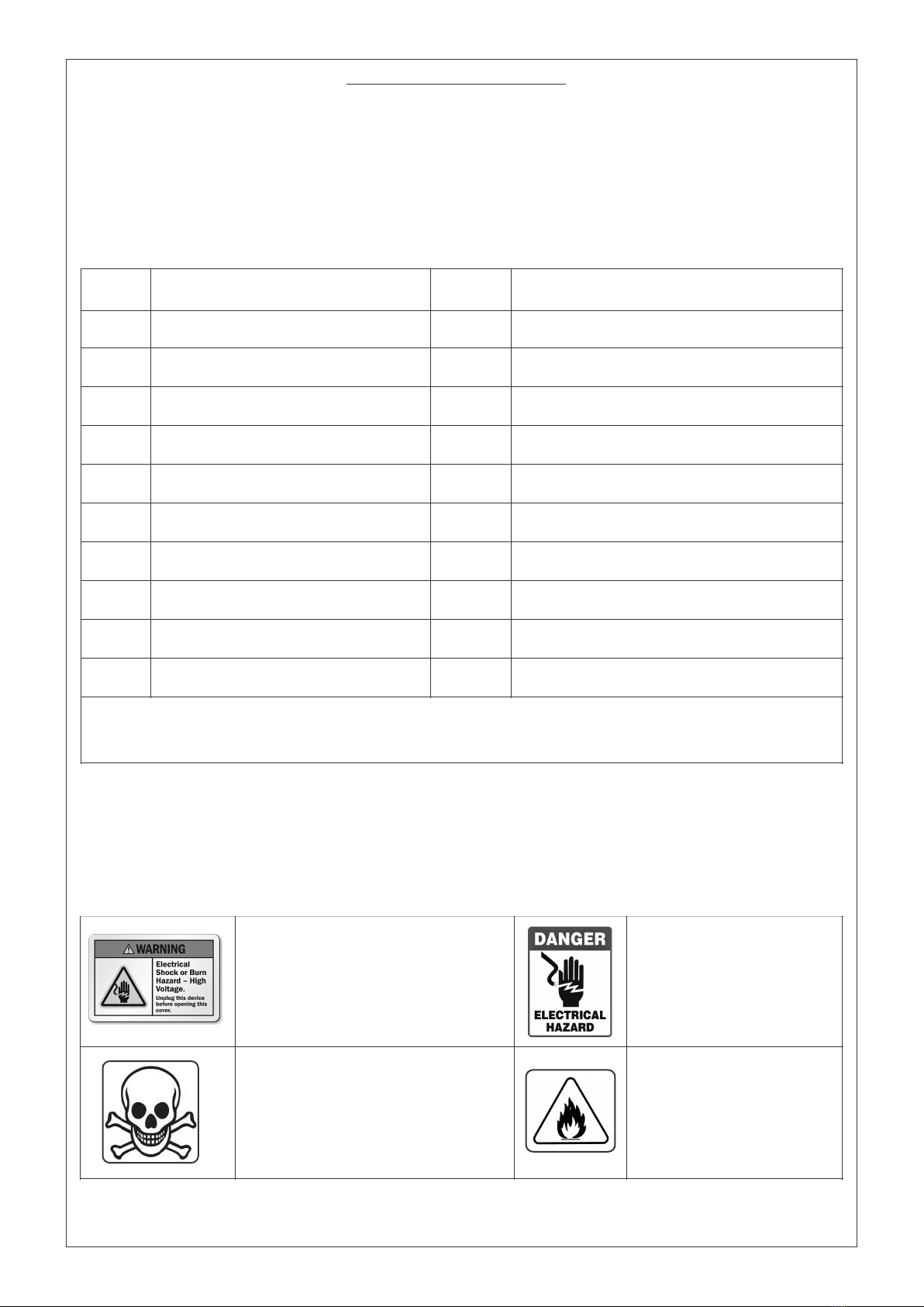
DANGER INDICATES A HAZARDOUS
SITUATION WHICH, IF AVOIDED, WILL
RESULT IN DEATH OR SERIOUS
INJURY.
WARNING! ELECTRICAL SHOCK
HAZARD. NO USER SERVICEABLE
PARTS INSIDE. REFER SERVICING TO
QUALIFIED SERVICE PERSONNEL.
DA N G E R E L E C T R I CA L
HAZARD. TURN OFF POWER
BEFORE SERVICING.
RISK OF FIRE
1.1 SCOPE OF VALIDITY
1.2 SYMBOL INDICATIONS:

4
1.3.4 PACKAGED CONTENTS:
Installation, maintenance & repair should be done by authorised, trained & experienced personnel
only.
Disconnect the battery, grid, solar panel & load before any service on the inverter to avoid
electrocution.
To disconnect the inverter, turn off the MCBs/Switch/Terminals on the PCU & remove the battery
fuse holder.
Use the PCU according to our instructions for operation.
Metal bracelets, rings and other metal objects should be removed before touching the PCU to avoid
contact with electricity carrying items.
Dispose the battery through the Govt-approved agencies only, as it contains lead and other harmful
chemicals.
Ensure that the unit is out of reach of small children who may be exposed to serious injuries
otherwise.
Do not place inverter/ battery in the environment of heating vents, near the radiations or other
source of heat.
1.3.1 GENERAL SAFETY RULES:
1.3.2 PRECAUTIONS DURING INSTALLATION & REPAIR:
1.3.3 PRODUCT SAFEGUARDING:
Grounding of PCU & Panel should be done prior to connecting power.
Before installation disconnect PV & Grid as they may start automatically under certain conditions.
Baking powder neutralizes battery acid electrolyte. Always keep some handy.
For disconnecting the battery first remove the negative terminal to avoid the spark.
High voltage is present at the battery terminals even after the inverter is shut down.
Before working on the unit always be assured the charge is discharged completely.
Be careful while working with metal tools to avoid short circuit.
PCU should be placed in accordance with the given instructions:
Routine checks should be carried out to monitor the system health.
Keep ventilation holes on the unit always open.
The system works well in areas where temperature does not exceed the range between 0°C to 50°C.
There should be no contact of the inside of the PCU with liquid of any kind as it may results in
a shorting of the circuit.
Dust free areas are preferred otherwise the performance may deteriorate over time resulting in a
system failure, lightning, rain and adverse conditions.
PCU
Product Manual
Spare Fuse (optional)
Warranty Card
Figure 1
1.3 SAFETY
MANUAL
PCU FUSE WARRANTY CARD
5
2. INTRODUCTION
The SEOG MPPT-Based PCUs are mechanically and electrically robust with a operating range and suitable for
operating in harsh environments. This unit is perfectly fit for low-maintenance for industrial and residential
applications both.
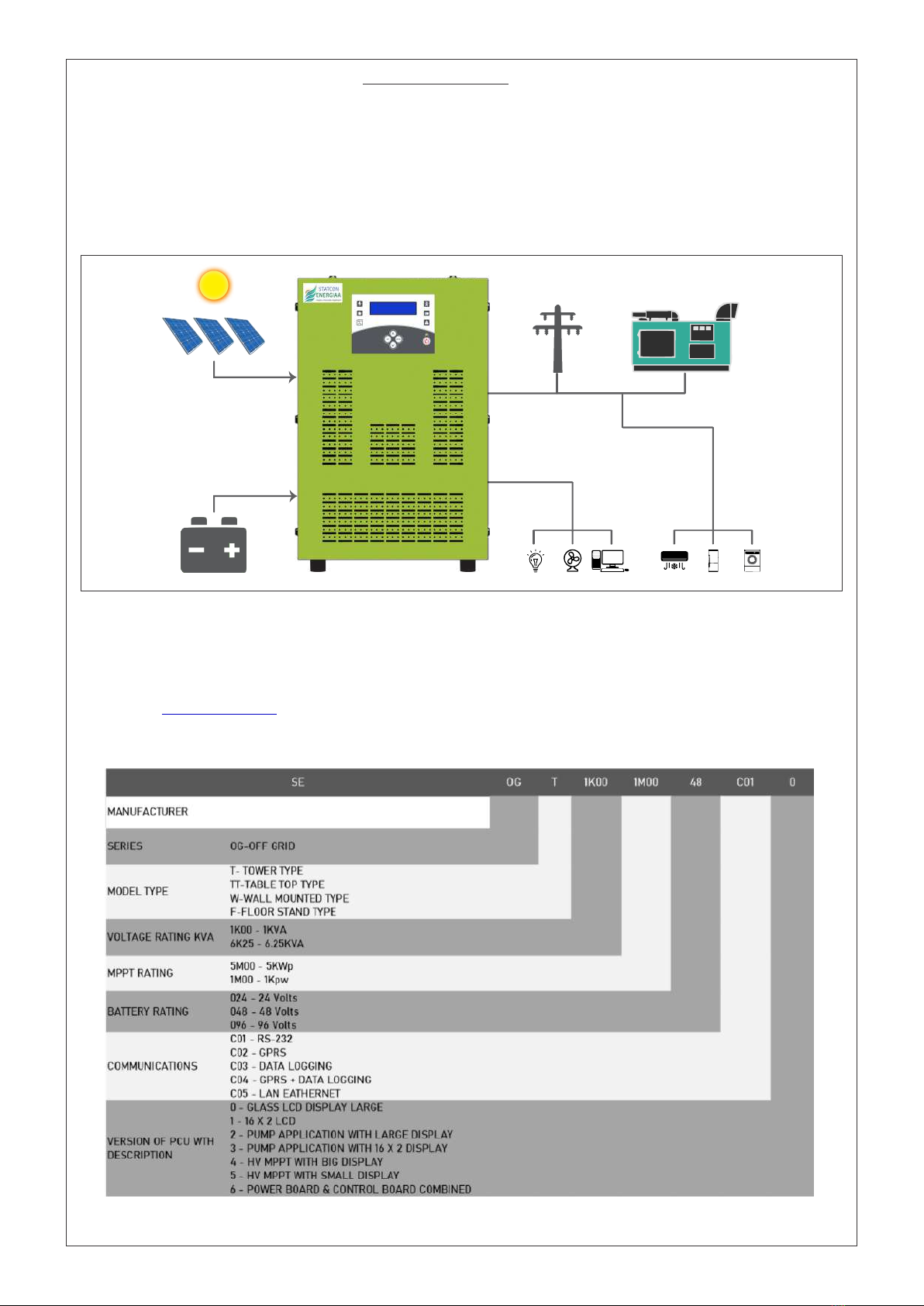
A typical block diagram is shown in Figure 2 involving the integration of SOLAR, GRID, BATTERY and GENSETS
with the site loads. its inbuilt Intelligence manages all the sources selectively to provide seamless power to the
loads so as to incur minimum bills with optimum utilization.
2.1 PRODUCT DESCRIPTION
Congratulations on being a part of the Indian solar revolution and buying a product that helps in sustainable
development, guarantees peace of mind and, more importantly, cuts a major portion of your electricity bill!
The solar Power Conditioning Unit (PCU) gives you the most savings through Solar PV + Battery + Mains.
Kindly visit to know more about our product range. Custom built ratings of inverter are also www.energiaa.in
available on request and can be designed as per user requirements.
Figure 2
2.2 PRODUCT NOMENCLATURE FOR SEOG MPPT-Based PCU
Figure 3

6
MAINS MCB
PV MCB
LOAD MCB
COMM. PORT
EARTHING
BOLT
BATT. MCB
MAINS INPUT
AC LOAD
OUTPUT
PV OUTPUT
BATTERY
INPUT
COOLING
FAN
Note : Please note that the dimensions, enclosure type, colour shade and cable entry can be changed by the
manufacturer without prior notice, owing to technological innovation.
2.3 PHYSICAL APPEARANCE & TERMINATION DETAILS OF INVERTER
SEOG MPPT-Based PCU comes in sheet metal enclosure of standard sizes and colour shades depending upon the
size of the machine. Any machine can be either Tower type or Table top type depending upon its capacity. All the
units are for Indoor application only and should not be kept in open.
All the wire connections to unit are made from the bottom end at rear side. The terminology and sequence of
terminals have been kept the same for as many models as possible for ease of understanding and has been
explained below in detail.
The below chart brings out all the variants available in terms of dimensions and capacity of the machine.
SR.
NO.
RATING
DIMENSIONS
(W X D X H)
ENCLOSURE
TYPE
COLOUR
SHADE
VIEWS
1
1-3 KVA Single Phase PCU
295 X 415 X 325
TABLE TYPE
GREEN/WHITE
Figure 4
2
4-6 KVA Single Phase PCU
300 X 680 X 475
TOWER TYPE
GREEN/WHITE
Figure 5
3
5-8 KVA Single Phase PCU
375 X 625 X 590
TOWER TYPE
BLACK
Figure 6
4
10 KVA Single Phase PCU
400 X 700 X 590
TOWER TYPE
BLACK
Figure 7
5
15 KVA Single Phase PCU
450 X 700 X 590
TOWER TYPE
BLACK
Figure 8
6
20 KVA Single Phase PCU
500 X 700 X 668
TOWER TYPE
BLACK
Figure 9
Table 2
2.3.2 SEOG - TOWER TYPE MODEL : 1-3 KVA/48V MPPT-Based PCU
Figure 4
FRONT VIEW REAR VIEW
STATCON
Inspire Innovate Implement
ENERG IAA

7
Mains
P N
Load
N P
PV
+ -
Battery
- +
Cooling Fan
Communication
Port
PV MCB
MAINS MCB
LOAD MCB
BATTERY MCB
Battery I/P
Terminals
Mains I/P
Terminals
Load O/P
Terminals
PV I/P
Terminals
2.3.3 SEOG - TOWER TYPE MODEL : 4-6 KVA/48V MPPT-Based PCU
Figure 5
FRONT VIEW REAR VIEW
2.3.4 SEOG - TOWER TYPE MODEL : 10KVA/96/120V MPPT-Based PCU
Figure 6
FRONT VIEW REAR VIEW
Batt. MCB
Batt.
Batt. Temp.
Sensor
Battery Temp.
Sensor
Communication
Port
Cooling Fan
RS-485
PV MCB Load
MCB
Mains
MCB
+ - PV
- + Load
PN
Mains
NP
Battery MCB
PV MCB
Mains MCB
Load MCB
Surge Protection
Device
Battery I/P
Terminals
PV I/P
Terminals
AC Load O/P
Terminals
Mains I/P
Terminals
Earthing
STATCON
Inspire Innovate Implement
ENERG IAA
STATCON
Inspire Innovate Implement
ENERG IAA
POWER CONDITIONING UNIT

8
2.3.5 SEOG - TOWER TYPE MODEL : 15KVA/240V MPPT-Based PCU
Figure 7
FRONT VIEW REAR VIEW
2.3.5 SEOG - TOWER TYPE MODEL : 15KVA/ 120V MPPT-Based PCU
Figure 8
AC Load O/P
Terminals
PV I/P
Terminals
Batt. Temp.
Sensor
Communication
Port
Battery Temp.
Sensor RS-485
Cooling Fan
Battery
MCCB
PV MCCB
Mains MCB
Load MCB
Batt.
MCCB
PV
MCCB
Load MCB Mains MCB
Mains I/P
Terminals
Battery I/P
Terminals
Surge Protection
Device
Earthing
AC Load O/P
Terminals
PV I/P
Terminals
Batt. Temp.
Sensor
Communication
Port
Battery Temp.
Sensor RS-485
Cooling Fan
Battery
MCCB
PV MCCB
Mains MCB
Load MCB
Batt.
MCCB
PV
MCCB
Load MCB Mains MCB
Mains I/P
Terminals
Battery I/P
Terminals
Surge Protection
Device
Earthing
FRONT VIEW REAR VIEW
STATCON
Inspire Innovate Implement
ENERG IAA
STATCON
Inspire Innovate Implement
ENERG IAA
POWER CONDITIONING UNIT
POWER CONDITIONING UNIT

9
AC Load O/P
Terminals
PV I/P
Terminals
Batt. Temp.
Sensor
Communication
Port
Battery Temp.
Sensor RS-485
Battery
MCCB
PV MCCB
Mains MCB
Load MCB
Mains I/P
Terminals
Battery I/P
Terminals
Earthing
2.3.5 SEOG - TOWER TYPE MODEL : 20KVA/ 240V MPPT-Based PCU
POWER CONDITIONING UNIT
Figure 9
FRONT VIEW
REAR VIEW
2.4 FEATURES
SEOG series PCU’s provide a complete solution for 230V AC, 50Hz power requirements. This series PCUs are
rich in the following features:
2.4.1 5 MODE PRIORITY SELECTION AS PER USER REQUIREMENT
2.4.2 MONITORING
2.4.3 INDUSTRIAL GRADE INVERTER
Designed for reliability against frequent grid variations
Our Transformer provides galvanic isolation & has a long life
Protective breakers at all inputs and outputs
2.4.4 PLUG IN PLAY
Designed for screw-type/ pin type terminal blocks for all input and output
Ideal for solar integrators due to ease of installation
Designed for hassle free commissioning
Note: Refer the OPERATING MODES (Table 5)-Page No.-19 and LOAD CHART (Table 6)-Page No.-20 for
details.
MODE-1 : Super Saver 40
MODE-2 : Super Saver 50
MODE-3 : Super Saver 60
MODE-4 : Backup Mode
MODE-5 : No Solar Mode
16x2 LCD display in its class for great visuals.
Inbuilt data loging capability up to 5 years (optional).
RS 232/RS 485, GRPS, remote monitoring available (optional).
STATCON
Inspire Innovate Implement
ENERG IAA

10
3. INSTALLATION
3.1 LOCATION AND PLACEMENT
3.0.1 PCU
The Inverter should be placed in accordance with the following:
Unpack PCU completely then unwrap the stretch film from PCU.
In a well-ventilated room.
Placed on a raised platform for better insulation from the ground, protection from water, and so on.
Gas cylinders, spray and other inflammable items should not be placed near it.
Should not be placed in direct sunlight, near running water or at excessively humid location.
In case the system is not going to be installed immediately, it must be stored carefully in vertical
position, as indicated on the packing and stored in a dry and sheltered room. Cover it with an
envelope (paper/light material cover) so that it is protected from dust.
If the inverter installation is over 6 months, be sure to charge batteries for at least 8 hours before
the first use.
3.0.2 BATTERY
Battery should be placed on a 3”(inch) ramp above from ground.
Battery bank terminals should always be insulated to avoid and electrical shock.
Batteries should preferably be placed in a separate room to avoid acidic fumes.
Length of cable from battery to PCU should be kept to minimum to avoid the losses. Cable sizing
should also be done keeping in mind to minimum the losses.
3.0.3 PV
Place the solar panels (PV) in the direction of maximum duration time of sun.
There should not be shadow of any object on the panel.
Should be placed at sufficient height.
Panel should be fixed properly.
Since India is located in northern hemisphere so solar panel’s face should true south direction.
Solar panel tilt angle lies between 10°-30° but it should be determined according to the latitude of
your position.
3.0.4 SURGE PROTECTION DEVICE (SPD)
Surge Protection are a part of plant installations and hence, should be installed in addition to
protection offered in PCU. Type and size surge protections vary from site to site and adequate
consultation should be done with a subject matter expert before selection of SPD.
Apart from SPD in AJB used for solar protection, additional SPD is recommended before PCU inside
the room.
Suitable SPD on AC side (both Grid and Load) is mandatory inside the room before PCU to avoid any
damage to it caused by surges. A typical such schematic drawing can be seen in figure below for
single phase PCU. An installer may contact some expert and use alternate scheme similar to this
reliable working of PCU and site.
See the image below on next page:

11
This image shows a typical single-line diagram showing use of SPD and earth connection there of.
Figure 10
12
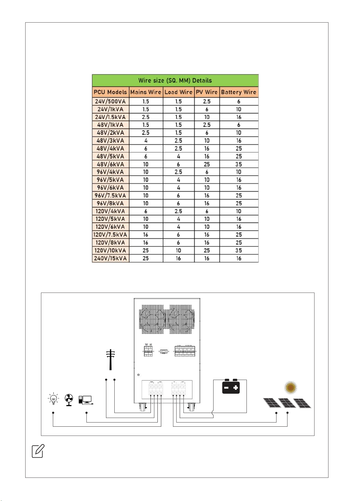
Figure 11
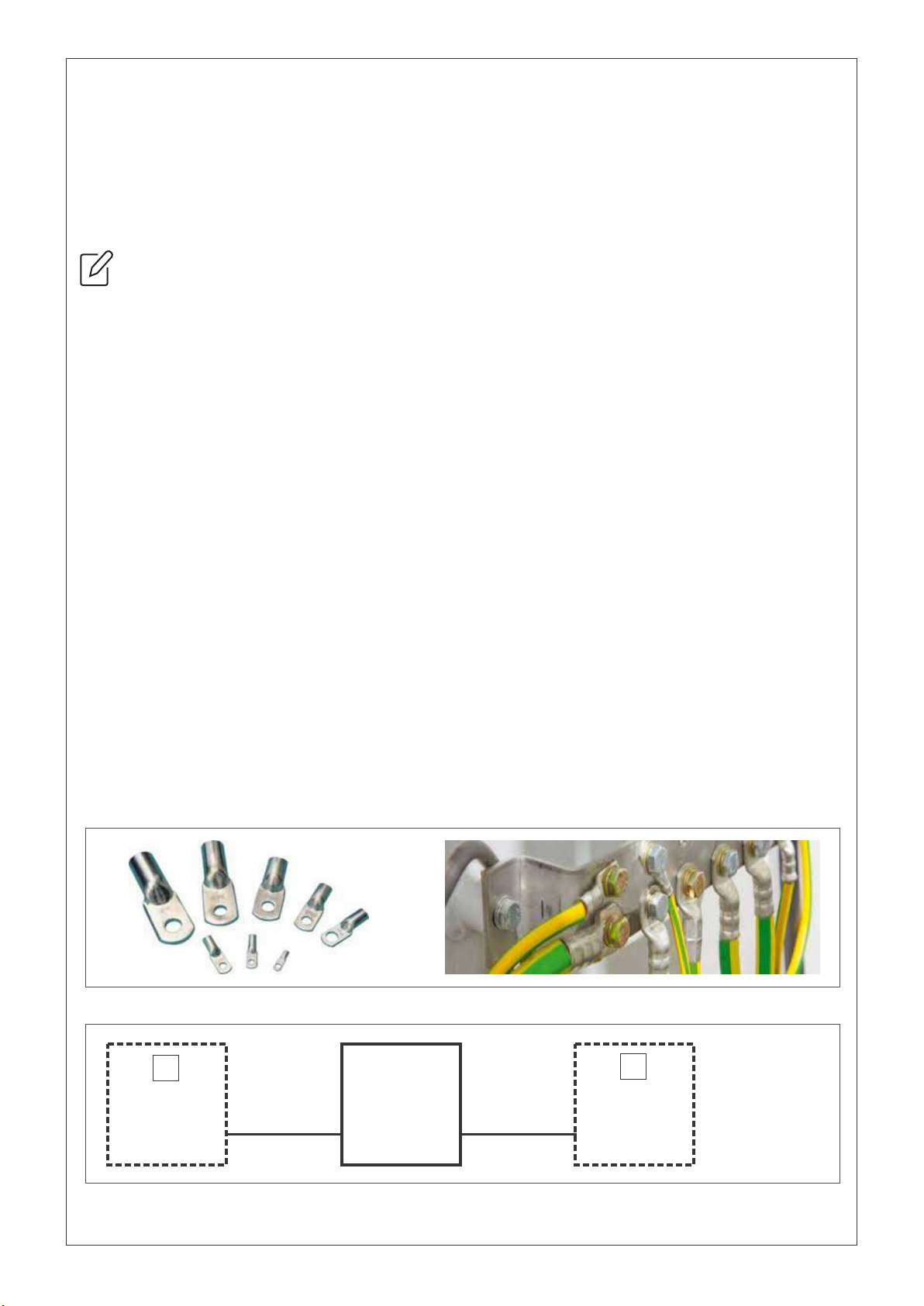
3.2 ELECTRICAL WIRING
WIRING AND THIMBLE/LUG SIZE CHART AS PER IS-3961-PART V
*THIMBLE/LUG DIA AT SCREW SIDE IS 6.2 MM. THIMBLE/LUG size should be same as wire size given
below.
Table 3
ENSURE THAT ALL THE MCB’s ARE IN OFF POSITION BEFORE STARTING THE CONNECTION.
L
N
N
L
Load
AC Mains
Battery
PV
13
3.3 ELECTRICAL CONNECTIONS
Connect the +ve terminal of the battery to the ‘BATT+’ terminal of PCU.
Connect the -ve terminal of the battery to the ‘BATT-’ terminal of PCU.
Keep wire to be of minimum possible length.
Follow the wire size and lug details as per given in Table 3.
BEFORE CONNECTING BATTERY WIRES MAKE SURE THAT ALL MCB’s ARE IN OFF POSITION.
3.2.1 CONNECTION TO THE BATTERY
Use a 2-core cable for connection of load to PCU.
The AC Mains must be connected to the screw/plug type terminals of AC Mains of PCU.
Connect the Phase wire of the AC Mains to the ‘L’ terminal of PCU.
Connect the Neutral wire of the AC Mains to the ‘N’ terminal of PCU.
Follow the wire size and lug details as per given in Table 3.
3.2.2 CONNECTION TO AC SUPPLY IN
The PV output must be connected to the ‘PV’ screw terminals of PCU.
Connect the +ve terminal of the PV output to the ‘PV+’ terminal of PCU.
Connect the -ve terminal of the PV output to the ‘PV-’ terminal of PCU.
Follow the wire size and lug details as per given in Table 3.
3.2.3 CONNECTION OF SOLAR MODULES (PV) : SOLAR IN
Use a 2-core cable for connection of load to PCU.
The AC load must be connected to Load terminals of PCU.
Connect the Phase wire of the Load to the ‘L’ terminal of PCU.
Connect the Neutral wire of the Load to the ‘N’ terminal of PCU.
Follow the wire size and lug details as per given in Table 3.
3.2.4 CONNECTION OF LOAD : LOAD OUT
3.4 INSTRUCTION TO FOLLOW
Charge the batteries before first use.
MCBs on the inverter should be OFF during connecting wires to the PCU.
Use thimbles for proper connection of wire at screw terminals
Figure 12
Figure 13
PCU
MAINS
I/P
O/P
STABILIZER/
CVT/SERVO
STABILIZER/
CVT/SERVO
NOTE:
DO NOT USE
STABILIZER/
CVT/SERVO
AT OUTPUT
OF PCU.
✓✕

14
3.5 EARTHING
Earthing of any equipment is required to ensure that the chassis of the equipment is at ground
potential and the user does not experience any shock in case of contact.
For SPDs to operate and protect the equipment against lightning, earthing is mandatory.
Quality of earting and related values are important for adequate protection and vary from site to site,
and equipment to equipment.
Earthing kit contains rod and clay-salt mixture.
For earthing, dig a 4-5 feet hole in ground and put the rod with mixture and water.
Connect the earth wire from house to clamp.
It is advisable to have a proper earthing near your house or solare panels.
Please ensure that earth connection of SPD as per section 3.0.4 above is as drawing.
3.6 STARTING UP THE PCU
Check all the connections twice before starting the PCU.
Ensure that:
Battery terminals (+ve to +ve & -ve to -ve) are connected tightly and properly.
Load is connected properly.
AC Mains is connected properly.
PV is connected properly.
Check the polarity correct.
After checking all the connections, Switch on the Battery MCB first.
After switching on the MCB, the display is switched ON.
Now switch ON all the MCB’s : AC Mains MCB, Load MCB and PV MCB.
Now press the power button given below the display for a few seconds till the green LED comes ON.
Your PCU will start now.
4. DISPLAY
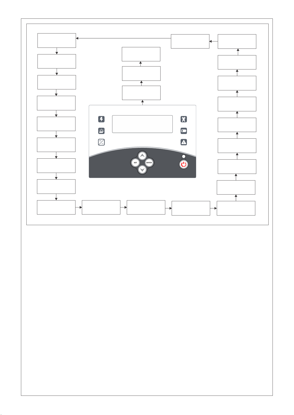
4.1 DISPLAY OVERVIEW
The Flow diagram of home display on the page shows the basis navigation of the display panel
through the buttons provided : namely INC, DEC, SET, ENTER.
The display automatically scrolls the parameters after the unit is switched ON.
Various parameters are displayed one after the other with a 5 second time period for each and 10
second delay for TIME and DATE.
Press “INC” key to see each parameter manually and now each parameter can be scrolled through
one by one by pressing INC key successively.
4.1 DISPLAY PARAMETERS
BATTERY : Voltage, Charging Current, Discharging Current, Temperature
PV : PV Voltage, PV Current, PV Power, PV Today’s kWH.
INVERTER : Voltage Current, Frequency, Load kVA.
GRID : Voltage, Frequency, Grid kVAh.
Date, Time.
15
Figure 14
System
Switched ON
1A
1B
STATCON ENERGIAA
PVT. LIMITED
Welcome Screen
Visit Us:
www.energiaa.in
MODEL NAME
System
Switched OFF
Bat Volt : 025.4V
Bat Amp : 000.0A
Battery
Boost Charging
Battery
Float Charging
Battery
Dis. Charging
Grid Volt : 230.1V
Grid Frq : 50.00Hz
Inv Volt : 000V
Inv Amp : 00.0A
PRIORITY MODE:
SUPER SAVER 40 PRIORITY MODE:
SUPER SAVER 50
PRIORITY MODE:
SUPER SAVER 60
PRIORITY MODE:
BACKUP
PRIORITY MODE:
NO SOLAR
2
3A
3B
3C
4
5
8A 8B 8C
8D
8E
Load Volt : 000V
Load Frq : 00Hz
Load % : 20.1
Load Frq : 00Hz
6
7
WORKING MODE:
UPS 9A
WORKING MODE:
W - UPS 9B
Grid Charging:
Enabled 10A
Grid Charging:
Disabled 10B
PV Volt : 000.0V
PV Amp : 000.0A 11
PV KW : 00.000KW
PV KWh : 00.000kWH 12
Total_Gen
00000000001 kWH
13
4.2 MENU SETTING
Long Press key SET to enter MENU setting Mode.
In MENU press key INC successively to go in DATA LOGGING MODE, USER MODE, USER SETTING
MODE, FACTORY SETTING MODE and PARAMETER CALIBRATION MODE. To exit from this mode press
ENTER.
4.3.1 DATA LOGGING MODE
Press key SET to enter in data mode when displayed on screen.
Press key SET to see days unit generation (KWh) day wise data.
Press key SET to see monthly unit generation (Kwh) data.
Press key SET to see year wise (Kwh) data.
Press key ENTER to exit this mode.
4.3.2 USER SETTING MODE
Press key SET to enter in user mode when displayed on screen.
After entering in user mode it will show software versions.
PC-UEr (XX.X) and dp-UEr (X.X)
After this, it will show rating of your PCU. e.g. 48-4 kVA.
Press key INC to select your battery type (LM/VRLA/NI-CAD). Now press key SET to select battery
capacity (Ah).
Using INC/DEC keys, we can change battery capacity. Now press SET key to choose priority mode
now.
Press key INC/DEC to choose your source priority mode (S>G>B*/S>G>B/G>B>G/S>G>B**/G>S>B).
Press key ENTER to save your settings. It will automatically return to main menu.
16
4.3.3 FACTORY SETTINGS MODE
This mode is password protected. (to be operated only by trained personnel of company).
4.3.4 PARAMETER CALIBRATION MODE
This mode is password protected. (to be operated only by trained personnel of company).
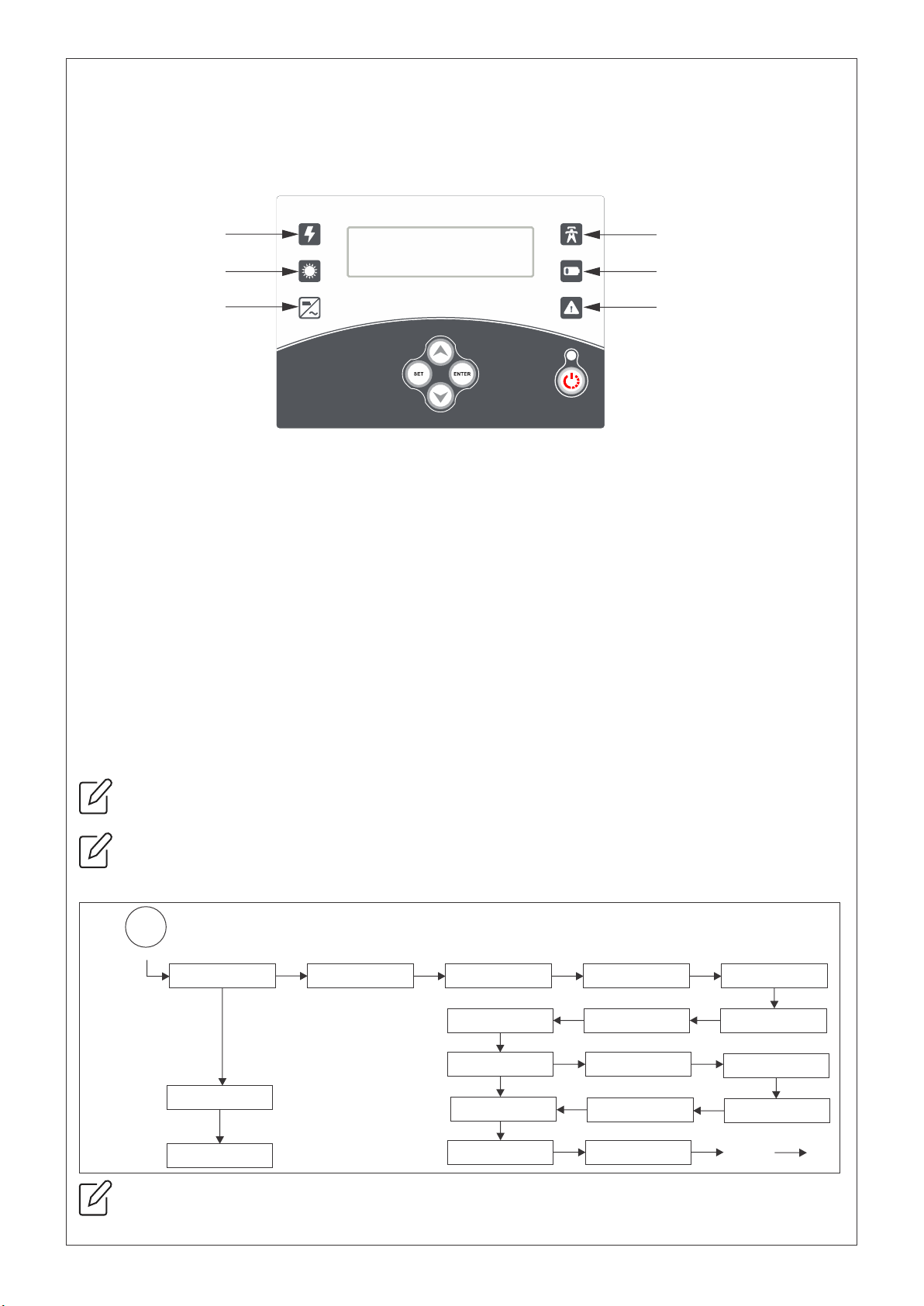
4.4 LED INDICATION
POWER : This green LED indicates PCU’s control circuitry is power ON.
INVERTER ON : This yellow LED glows when AC load is on INVERTER.
SOLAR ON : This yellow LED glows in steady state - this tells that the solar present and the
charging is completed/stoped. When blinking, it tells the solar is present and the charging is in
process
GRID ON : This yellow LED glows in steady state - this tells that grid is present and the load are
bypassed on GRID supply. When blinking with 1 second interval, it tells that (i)the grid is present, (ii)
the grid charging is in process and , (iii) the load is running on GRID supply. When blinking with a 5
second interval, it means that the GRID supply is available and the loads are running on PV+Battery.
BATT LOW : This red LED glow when your battery is low/discharged. Once Battery voltage falls below
Battery Under Voltage set value; Inverter will shut down and disconnect the load to stop further
discharging of battery. Next, “BATT. LOW” indication will appear on the display. Now Inverter will
again given the O/P to load only when Battery Voltage rises up to more than float voltage set value.
FAULT : This red LED glow if any Fault occurs.
INV ON/OFF : Press and hold button to turn on your PCU, green LED nearby button will start glowing,
which indicates inverter is switched ON.
Figure 15
GRID
BATT. LOW
FAULT
POWER
SOLAR
INVERTER
PRESS AND HOLD BUTTON TO TURN ON YOUR PCU, GREEN LED NEARBY BUTTON WILL START
GLOWING, WHICH INDICATES INVERTER IS SWITCHED ON.
LED OF CHARGING SOURCE WILL KEEP BLINKING DURING CHARGING.
4.5 MENU SETTING FLOW CHART
User Login
USER MODE MODE
UP
UP
UP
UP UP
UP
DOWN
DOWN DOWN
DOWN DOWN
DOWN
MODE
UP/DOWN
MODE
LONG PRESS SET BUTTON
Ctrl S/W Ver 4.7 PCU Rating
Type of Batt:Cell Capacity:Priority Mode:
Type of Batt: Type of Batt:
Priority Mode: Priority Mode: Priority Mode:
Priority Mode:
Grid Charging:
Grid Charging:
Working Mode: Working Mode:
Factory Login FACTORY MODE
CALIBRATION MODE
Calibration
Dis S/W Ver 1.5
Flat Plate0200AHSuper Saver
Tubular SMF
Saver Backup Smart
No Solar
Enabled
Disabled
UPS W - UPS ENT/ESC EXIT
IN USER SETTING MODE BATTERY TYPE, BATTERY CAPACITY & PRIORITY MODE MUST BE CHOSEN
PROPERLY AS PER YOUR REQUIREMENT.
Figure 16
17
4.6 FAULT ANALYSIS
4.6.1 FAULT / ALARM INDICATION VIA BUZZER
In the PCU system, if any fault/alarm occurs then an audio alarm indication is generated by a buzzer -a
continuous beep sound. By pressing ENTER key after checking the fault type in LED/LCD, buzzer sound gets
deactivated.
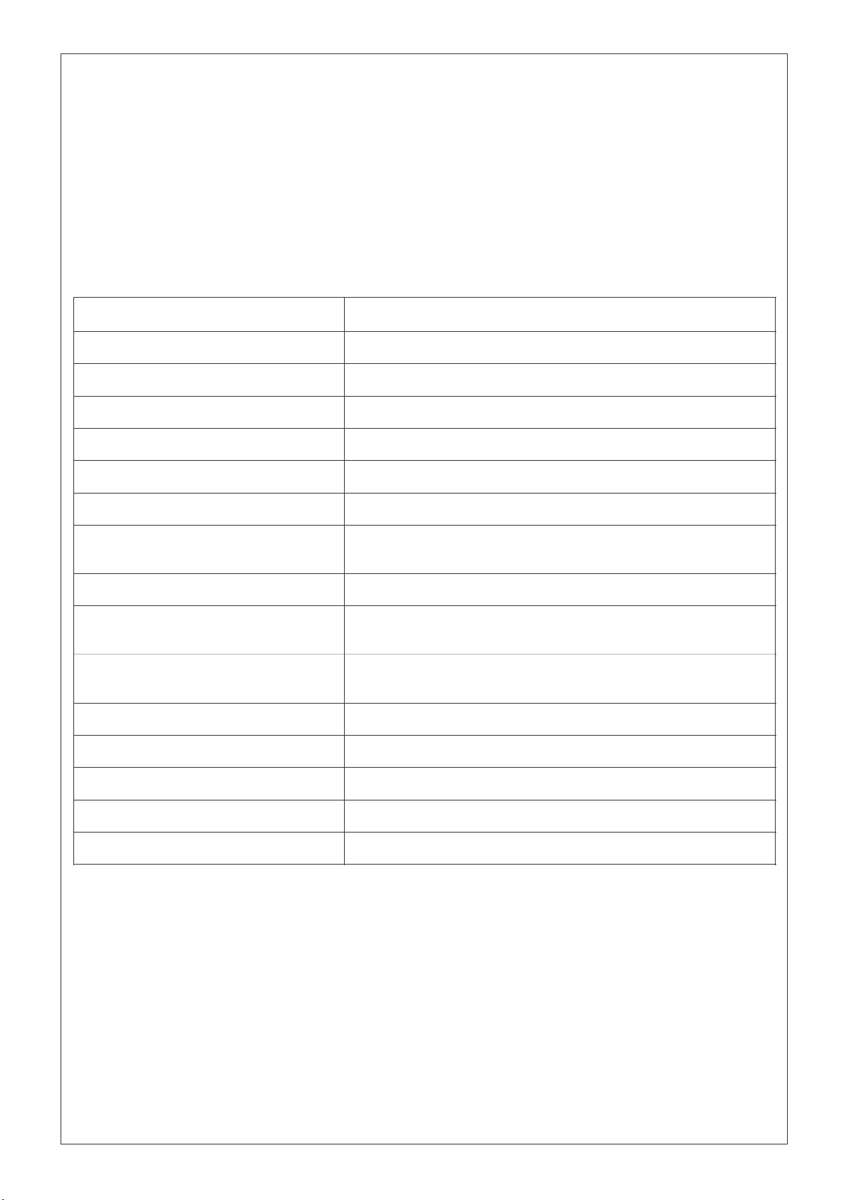
4.6.2 FAULT DISPLAY
If any fault occurs in the PCU system, predefined fault no. start display in upper right side of the LCD display
with the FAULT*--- as a prefix with each fault number. The lists of fault name are given in the Table 4 as per
their respective fault number/codes.
Table 4
FAULT NAME IN DISPLAY
FAULT DESCRIPTION
SYSTEM TRIP/OFF
When system Shuts Down due to any fault/internal error
INVERTER UNDER VOLTAGE
When Inverter O/P Voltage goes below inverter under voltage set value
INVERTER OVER VOLTGE
When Inverter O/P Voltage goes above inverter over voltage set value
BATTERY UNDER VOLTAGE
When Battery Voltage goes below the battery under voltage set value
BATTERY OVER VOLTAGE
When Battery voltage goes above the battery over voltage set value
SOLAR CHARGE OVER LOAD
When Over Rated PV panel connected to the system
PV OVER VOLTAGE
When PV panel or PV string voltage connected beyond the maximum
allowe PV voltage range value
SYSTEM OVER LOAD
When Inverter O/P Load goes above the rated system
GRID UNDER FREQUENCY
When Grid/DG supply frequency goes below the under frequency set
value
GRID OVER FREQUENCY
When Grid/DG supply frequency goes above the over frequency set
value
SHORT CIRCUIT
It Indicates that Inverter O/P short circuited
SYSTEM OVER TEMPRATURE
When temperature of inverter system goes above the safe range
GRID BACK FEED
When Grid supply connected to the load point directly
MAINS OVER VOLTAGE
When mains voltage goes above the set grid over voltage value
MAINS UNDER VOLTAGE
When mains voltage goes below the set grid under voltage value

18
5. OPERATING MODES AND LOAD CHART
5.1 DETAILS OF PRIORITY MODES
Note: Above stated battery’s SOC in percentage is estimated (based on Battery Voltage only) but not
actual. This holds true for all percentage mentioned in the table above.
Table 5
MODES
EXPLANATION OF MODE / REASON TO SELECT THE MODE
Super
Saver 40
Solar+Battery will run loads till battery reaches 40% DOD. At 40% DOD, grid will bypass to load,
and solar power if available will charge the battery. Grid charging of battery will start if battery
reaches 60% DOD. (only applicable if grid charging is enabled)*
Super
Saver 50
Solar+Battery will run loads till battery reaches 50% DOD. At 50% DOD, grid will bypass to load,
and solar power if available will charge the battery. Grid charging of battery will start if battery
reaches 70% DOD. (Only applicable if grid charging is enabled)*
Super
Saver 60
Solar+Battery will run loads till battery reaches 60% DOD. At 60% DOD, grid will bypass to load, and
solar power if available will charge the battery. Grid charging of battery will start if battery
reaches 80% DOD. (Only applicable if grid charging is enabled)*
Backup
Mode
Suitable for areas where grid supply is available only for 6-8 hours in a day. So, whenever grid
available it charges the battery up-to more than 80% of its capacity to make sure to get more
battery backup in night time as compared to above 3 modes.*
No Solar
Suitable for areas when sufficient solar power is not available for long duration (i.e. in rainy days
or where solar panel non available due to some reason). By selecting this mode PCU will run like
conventional home inverter.

19
5.3 LOAD CHART & BATTERY SIZING
PCU must be chosen as per load requirement, as this affects the life of your battery as well as the
PCU. Manufacturer shall not be responsible for the selection of mode as well as the size of the
PCU (that can only be determined by the installer/end-user).
PCU
Rating
24V-1KVA
48V-3KVA
96V-4KVA
96V-6KVA
QTY
TOTAL
WATSS
QTY
TOTAL
WATTS
QTY
TOTAL
WATTS
QTY
TOTAL
WATTS
*LOADS
15W
3
45
6
90
12
180
15
225
40W
1
40
3
120
6
240
10
400
60W
2
120
4
240
8
480
12
720
150W
1
150
2
300
3
450
4
600
250W
1
250
1
250
1
250
2
500
350W
—
–
1
350
1
350
2
700
450W
—
—
1
450
1
450
1
450
TOTAL
605W
1800W
2400W
3595W
BATTERY
SIZING
12V X 2 = 24V
70Ah X 2 = 140Ah
12V X 4 = 48V
100Ah X 4 = 400Ah
12V X 8 = 96V
70Ah X 8 = 560Ah
12V X 8 = 96V
100Ah X 8 = 800Ah
Table 6
*These ratings are based on assumption of load rating, battery rating and consumption of power by battery
for charging & operation of load for 1 hours.
Other manuals for SEOG Series
1
This manual suits for next models
20
Table of contents
Other STATCON ENERGIAA Inverter manuals


