Status Instruments DM4500U User manual

Page 1 of 54
PROCESS CONTROL
TEMPERATURE AND
LOAD CELL INDICATOR
INSTRUCTION MANUAL
DM4500U

Page 2 of 54

Page 3 of 54
INDEX
1. OVERVIEW ...................................................................................... 4
1.1. Introduction to DM4500U.................................................................... 4
2. GETTING STARTED ......................................................................... 5
2.1. Power supp y and connectors.............................................................. 9
2.2. Instrument front pane ....................................................................... 11
2.3. Programming instructions ................................................................... 11
3. INPUT CONFIGURATION................................................................ 13
3.1. Process input Programming................................................................. 15
3.1.1. Transducer connection (V, mA) .............................................. 15
3.1.2. Wiring diagram for mA input .................................................. 16
3.1.3. Wiring diagram for V input..................................................... 17
3.2. Load ce input Programming............................................................... 18
3.2.1. Load ce connection (mV/ V) ................................................. 19
3.3. Thermometer Pt 100 input programming ............................................. 20
3.3.1. Pt100 input connection .......................................................... 21
3.4. Thermocoup e input programming....................................................... 22
3.4.1. Thermocoup e input connection (J, K, T) ................................ 24
4. DISPLAY PROGRAMMING .............................................................. 25
4.1. Sca e ................................................................................................. 26
4.1.1. Sca e programming ............................................................... 28
4.2. Fi ter................................................................................................ 30
4.3. Round ............................................................................................. 30
4.4. Brightness........................................................................................ 30
4.5. Tare Mode ....................................................................................... 30
5. FUNCTIONS BY KEYBOARD AND BY CONNECTOR........................ 33
5.1. Functions by keyboard........................................................................ 33
5.2. Functions by connector....................................................................... 36
5.2.1. Logica functions diagram ...................................................... 37
5.2.2. Tab e of programmab e functions .......................................... 37
5.2.3. Functions programming ......................................................... 38
6. PROGRAMMING LOCK-OUT BY SOFTWARE .................................. 39
6.1. Security menu diagram....................................................................... 40
7. OUTPUT OPTIONS .......................................................................... 43
7.1. SETPOINTS OUTPUT .......................................................................... 44
7.1.1. Introduction.......................................................................... 44
7.1.2. Functioning description.......................................................... 44
7.1.3. Wiring .................................................................................. 46
7.1.4. Technica Specifications / setpoints ........................................ 47
7.1.5. Setpoints menu diagram ....................................................... 48
7.1.6. Direct access to programming of setpoints va ue .................... 49
7.2. ANALOG OUTPUT............................................................................... 50
7.2.1. Introduction.......................................................................... 50
7.2.2. Technica Specifications / ana og ............................................ 51
7.2.3. Ana og output menu Diagram ................................................ 51
TEC NICAL SPECIFICATIONS ....................................................... 52

Page 4 of 54
1. OVERVIEW
1.1 Introduction to model DM4500U
The DM4500U mode is a digita mu tifunction instrument which
a ows the user to program the input as a:
- PROCESS INPUT (V, mA)
- LOAD CELL INPUT (mV)
- Pt100 INPUT
- THERMOCOUPLE INPUT (J, K, T)
The basic instrument is a so dered assemb y composed of a main
board, a tricolor programmable display and a power circuit.
Standard features of the basic instrument inc ude the reading of the
input variab e as we as remote ho d, reading and memorisation of
max and min va ues (peak/ va ey), tare and reset function, and a
fu comp ement of programmab e ogic functions.
In addition, a variety of output options can be insta ed at the
factory from the ist be ow :
COMMUNICATION
OPT4500/485 Seria RS485
CONTROL
OPT4500/mA Ana ogue (4 to 20) mA
OPT4500/V Ana ogue (0 to 10) V
OPT4500/2R (2 x Re ays SPDT 8A)
OPT4500/4R (4 Re ays SPST 5A)
OPT4500/NPN (4 NPN output)
OPT4500/PNP (4 PNP output)
A the output options are opto iso ated from input signa and power
supp y.
This instrument conforms to the fo owing community
standards: 89/336/CEE and 73/23/CEE
Warning: Refer to the instruction manua to preserve
safety protection.

Page 5 of 54
2. GETTING STARTED
Packing contents
Instruction manua
Digita pane meter DM4500U
Accessories for pane mounting (sea ing gasket and fixing
c ips).
Accessories for wiring connections (p ug-in termina b ock
connectors with a fingertip key).
Wiring abe (fixed to the product housing).
Legend abe with engineering units.
Check the packing contents.
Programming instructions
The Instrument is programmab e via the front pane keyboard
and a ows access to severa independent programming menus
for configuration of the input, the disp ay and the ogic
functions. If additiona options are insta ed (seria outputs,
ana ogue output and re ays output) once recognised by the
instrument, they activate their own programming software.
Programming lock-out (See section 6).
The software can be configured to a ow tota programming ockout
but a so se ective ockout of the programming parameters.
The instrument is de ivered from the factory with un ocked
programming, e.g., with a the programming eve s accessib e
to the operator
TIP! - Write down the security code and keep it in a secure
place.

Page 6 of 54
Front: 96 x 48 mm
Depth: 60 mm
Panel cut-out: 92 x 45 mm
CLEAN NG:
Front cover should be cleaned only
with a soft cloth soaked in neutral
soap product.
DO NOT USE SOLVENTS
Dimensions and mounting

Page 7 of 54
Programming the instrument.
First, connect the instrument to the corresponding supp y;
automatica y, a disp ay test wi be done and the software version
wi be shown, then the instrument wi go to run mode.
Next, press the
key to enter into the programming mode;
the indication "-Pro-" wi appear on the disp ay.
ow to store programmed parameters?
To save the changes that have been programmed, the operator
must comp ete the programming of a the parameters contained in
the current routine. In the ast step of the routine, by pressing the
key, “StorE” wi be disp ayed and a changes are stored in
memory. Then the instrument wi return to the run mode.
ow is programming routine organised?
Programming software is composed by a number of menus and
submenus. In the diagram be ow, beginning with indication "-Pro-",
press repeated y to get access to programming menus. B ocks
3, 4 and 5 re ate to output options and wi on y be shown if the
option is fitted.
Se ecting one menu, access to the different programming
submenus is done by pressing
.
Modu e se ection eve

Page 8 of 54
Access to programmed parameters
Because of the menu structure, the programming routines a ow
access to change one parameter without passing through the who e
ist of parameters.
To advance through programming
Progress through programming routines is done by pressing
key.
In genera , push key a certain number of times to se ect an
option and push key to va idate the change and to go forward
to the next step of the program.
The numerica va ues are programmed digit by digit as exp ained in
the next paragraph.
Programming numerical values
When the parameter is a numerica va ue, the disp ay wi show the
first digit to be programmed f ashing.
Digit selecting: Press repeated y the key to shift from eft to
right over a the disp ay digits.
Changing the digit value: Press the
key repeated y to
increase the va ue of f ashing digit unti it has the desired va ue.
The minus sign is programmed depending on the variab e type. A
variab e that represents the va ue of an input wi be ab e to take a
va ue in the range -19999 to 99999, without taking into account the
decima point. When changing the first digit, this shows va ues from
(0) to (9), and then (-1), (-), and comes back to show va ues from
0 to 9.
A variab e that represents a disp ay va ue wi be ab e to take a
va ue in the range -19999 to 99999, without taking into account the
decima point. In these case the first digit shows 0, 1, -1 or -.

Page 9 of 54
Selecting an option from the list
When the parameter is an option to be chosen among different
possibi ities, the key a ows you to browse through the ist of
options unti you find the desired parameter.
2.1 – Power Supply and connectors
WARNING: If not installed and used in accordance with
these instructions, protection against hazards may be
impaired.
In order to guarantee the e ectromagnetic compatibi ity, the
fo owing guide ines shou d be kept in mind:
-Power supp y wires shou d be
routed separate y from signa
wires.
-Never run power and signa wires
in the same conduit.
-Use shie ded cab e for signa
wiring and connect the shie d to
the ground of the indicator.
-The cab e section shou d be >0.25
mm2
INSTALLATION
To meet the requirements of the directive EN61010-1, where the
unit is permanent y connected to the mains supp y, it is ob igatory
to insta a circuit breaking device within easy reach of the operator
and c ear y marked as the disconnect device.
1
2

Page 10 of 54
WIRING and POWER SUPPLY RANGE
DM4500/S1
(85 to 265) VAC (50 to 60) Hz, or (100 to 300) VDC
DM4500/S2
(22 to 53) VAC (50 to 60) Hz, or (10.5 to 70) VDC
Pin 1: Live
Pin 2: Neutra
CONNECTORS
CN1 To perform wiring connections, strip the
wire eaving between (7 and 10) mm exposed
and insert it in the required termina whi e
pushing the c amp too down to open the c amp
inside the connector as indicated in the figures.
CN1 termina accepts cab es of section between
0.33 mm² and 2 mm² (22 to 14 AWG)
Recommended cab es size 2.0 mm²
CN2 & CN3 To perform wiring
connections, strip the wire eaving
between (5 and 6) mm exposed and
insert it in the required termina whi e
pushing the fingertip too in to open
the c amp inside the connector as
indicated in the figures.
Each termina accepts cab es of
section between 0.08 mm² and 0.5
mm² (28 to 20 AWG)
Recommended cab es size 0.5 mm²

Page 11 of 54
2.2 –Instrument frontal view
2.3 – Programming guide
To programme the product to accept different sensor types,
p ease see the sections be ow. To save time we have
marked paragraphs as ob igatory (O), recommendab e (R)
or optiona (op).
As Process indicator:
1. Input Configuration (Sec. 3.1) (O).
2. Input Connection (Sec. 3.1.1/2 & 3) (O).
3. Disp ay Configuration (Sec. 4) (O).
4. Program remote inputs (Sec. 5.2) (R).
5. Insta and configure output option(s) (Sec. 7) (op)
6. Programming ock-out (Sec. 6) (R).
As thermometer Pt100:
1. Input Configuration (Sec. 3.3) (O).
2. Input Connection (Sec. 3.3.1) (O).
3. Program remote inputs (Sec. 5.2) (R).
4. Insta and configure output option(s) (Sec. 7) (op).
5. Programming ock-out (Sec. 6) (R).
As Load cell indicator
1. Input Configuration (Sec. 3.2) (O).
2. Input Connection (Sec. 3.2.1) (O).
3. Disp ay Configuration (Sec. 4) (O).
4. Program remote inputs (Sec. 5.2) (R).
5. Insta and configure output option(s) (Sec. 7) (op).
6. Programming ock-out (Sec. 6) (R).

Page 12 of 54
As thermometer thermocouple:
1. Input Configuration (Sec. 3.4) (O).
2. Input Connection (Sec. 3.4.1) (O).
3. Program remote inputs (Sec. 5.2) (R).
4. Insta and configure output option(s) (Sec. 7) (op).
5. Programming ock-out (Sec. 6) (R).

Page 13 of 54
3. INPUT CONFIGURATION
The figure be ow shows the input configuration menu. Divided into
four submenus, each one of them separated by the dotted ine in
the manua , each menu corresponds to the programming of the
different types of input: process, oad ce , thermometer Pt100 and
thermometer thermocoup e. The data requested in each case is
indicated be ow.
Cn nP
ProC
10 V
- Pro -
20 mA
LoAd
15 mV
- Pro -
30 mA
Process:
Input type
and
ranges
±(0 to 10) V
or
±(0 to 20) mA
Load Cell:
Input ranges
±15 mV, ±30 mV, ±150 mV
150
mA
tEMP
Pt 100
°C °F
Thermocouple :
Type: J,K & T ranges
Units: °C, °F
Resolution: 0.1°, 1°
Offset -9.9° to +9.9°
-99° to +99°
0.1 °C 1 °C
00.0 Offset
- tC -
- J - - K -
- °C - - °F -
- T -
0.1 °C 1 °C
00.0 Offset
- Pro -
- Pro -
Pt100 :
Units: °C, °F
Resolution: 0.1°, 1°
Offset -9.9° to +9.9°
-99° to +99°

Page 14 of 54
Pro Top Level (Programming menu entry point)
CnInp Level 1
Channe Input; for se ecting the correct type of input configuration for the sensor
to be used.
Options avai ab e; Proc, LoAd, tEMP
Proc Level 2
(See Sec. 3.1)
LoAd Level 2
(See Sec. 3.2)
Process input type se ection. Load ce input se ection
Options avai ab e; 10 V, 20 mA Options avai ab e; 15 mV, 30 mV,
150 mV
10 V Sub level 15 mV Sub level
Input range +/ (0 to 10) V Input range (-15 to 15) mV
20 mA Sub level 30 mV Sub level
Input range +/ (0 to 20) mA Input range (-30 to 30) mV
150 mV Sub level
Input range (-150 to 150) mV
Temp Level 2
Temperature input type se ection. Options avai ab e are PT100 and TC
Pt100 Level 3 See 3.3 tC Level 3 See 3.4
Pt100 input type configuration,
options avai ab e are:
Disp ay unit, Disp ay reso ution, User
offset
Thermocoup e input type
configuration, options avai ab e are:
TC type, Disp ay unit, Disp ay
reso ution, User offset
J, K, T Sub level
TC type se ection.
°C or °F Sub level
The disp ayed temperature unit can be se ected.
0.1° or 1° Sub level
The disp ay reso ution can be se ected.
Offset Sub level
A va ue can be entered by the user which wi be app ied to the measured va ue
before it is disp ayed. The va ue entered is app ied across the entire measurement
range. This can be used to tune out system errors.

Page 15 of 54
3.1 – Program process input
When used as a process indicator, the parameter to configure is the
input type, in vo ts (-10 to 10) Vdc range or in mi iamperes (-20 to
20) mA range.
3.1.1 – Sensor connection (V, mA)
Refer to wiring guide ines in (Sec. 3.1.2/3)
Instrument rear view
CONNECTOR SIGNAL INPUT
CN2
PIN 1 = -EXC [excitation output (-)]
PIN 2 = +EXC [excitation output +24 V (+)]
PIN 3 = +EXC [excitation output +5 V or 10 V (+)]
PIN 4 = N/C [no connection]
PIN 5 = +IN [input mA (+)]
PIN 6 = +IN [input V (+)]
PIN 7 = N/C [no connection]
PIN 8 = -IN [input V (-), mA (-)]
CN2
1 2 3 4
5 6 7 8

Page 16 of 54
3.1.2 WIRING DIAGRAM FOR INPUT Ma
(±0 to 20) mA / (4 to 20) mA
-
+ EXC
+ OUT
- mA
+ mA
2 wire connection
[ only (4 to 20) mA ]
1
8
EXTERNAL
EXCITATION
SENSOR
(4 to 20) mA
- EXC
+ EXC
+ OUT
- OUT- mA
+ mA
4 wire
connection
1
8
SENSOR
(0 to 20) mA
(4 to 20) mA
+ mA
+ EXC
+ OUT
1
8
SENSOR
(4 to 20) mA
2 wire connection
[ only (4 to 20) mA ]
External Excitation
Internal Excitation
- EXC
+ EXC
+ OUT
- OUT
- mA
+ mA
1
8
EXTERNAL
EXCITATION SENSOR
(0 to 20) mA
(4 to 20) mA
4 wire
connection
EXTERNAL
EXCITATION
-
+ EXC
+ OUT
CO- mA
+ mA
SENSOR
(0 to 20) mA
(4 to 20) mA
1
8
3
wire connection
+ EXC
+ OUT
CO- mA
+ mA
1
8
SENSOR
(0 to 20) mA
(4 to 20) mA
3
wire connection
If the excitation supplied by the unit to
the sensor has to be (5 or 10) V connect
the +EXC wire to PIN3 instead of PIN2

Page 17 of 54
3.1.3 WIRING DIAGRAM FOR INPUT V (±0 to 10) V
If the excitation supplied by the unit to
the sensor has to be (5 or 10) V connect
the +EXC wire to PIN3 instead of PIN2
-
+
+ OUT
- OUT
- V
+ V
DM
4500U
1
8
EXTERNAL
EXCITATION
SENSOR
(0 to 10) V
3 wire
connection
- V
+ V
1
8
EXTERNAL
EXCITATION - EXC
+ EXC
+ OUT
- OUT
4 wire
connection
SENSOR
(0 to 10) V
DM
4500U
- V
+ V
DM
4500U
1
8
- EXC
+ EXC
+ OUT
- OUT
4 wire
connection
SENSOR
(0 to 10) V
- V
+ V
DM
4500U
1
8
+ EXC
+ OUT
- OUT
3 wire
connection
SENSOR
(0 to 10) V
+ OUT
- OUT
- V
+ V
DM
4500U
1
8
SENSOR
(0 to 10) V
2 wire
connection
+ EXC (10 V)
- V
+ V
1
8
+ OUT
- OUT
Poteniometer
DM
4500U

Page 18 of 54
3.2 – Programming of Load cell input
Refer to ce manufacturer’s documentation, particu ar y with
respect to the ce sensitivity and supp y vo tage specifications.
As oad ce indicator, the meter’s function is to measure forces
(weight, pressure, torque...) app ied to a sensing e ement
connected to severa bridge type transducers, such as oad ce ,
which supp y signa eve s up to ±150 mV.
The two excitation vo tages supp ied by this instrument are 10 V
and 5 V. The se ection is rea ised through the configuration of the
interna bridge excitation (see diagram be ow). This way up to 2
ce s can be connected in para e with 10 V excitation and up to 4
ce s with 5 V excitation, without need for an externa source (see
connection (Sec. 3.2.1)).
Examp e:
2 ce s with 2 mV/V output are supp ied with an excitation
vo tage of 10 V; the vo tage generated by each ce at fu
oad is 20 mV. Therefore 20 mV is the maximum output as
the ce s are connected in para e . In the same case but
with a 5 V excitation, the maximum vo tage generated wi
be 10 mV.
Software configuration requires programming of the input mV range
which can be se ected from a choice of 3 ranges to avoid ‘out of
range’ signa s. There are three ranges: ±15 mV, ±30 mV and ±150
mV
Examp e:
If a weighing process gives 12 mV to the meter input with
maximum oad, the best input range to se ect wi be "15 mV".
Selection of voltage excitation 10 V or 5 V
5 V Exc. Jumper on
10 V Exc. Jumper off

Page 19 of 54
3.2.1 – Load cell connection (mV/ V)
Refer to wiring guide ines (Sec. 2.1).
Instrument rear view
CONNECTOR SIGNAL INPUT (CN2)
PIN 1 = -EXC [excitation output (-)]
PIN 2 +EXC [no connection]
PIN 3 = +EXC [excitation output +5 V or 10 V (+)]
PIN 4 = N/C [no connection]
PIN 5 = N/C [no connection]
PIN 6 = N/C [no connection]
PIN 7 = +mV [input mV (+)]
PIN 8 = -mV [input mV (-)]
+
OUT
-
OUT
7
+IN
-
IN
1
3
8
-
+
+EXC
-
EXC
1
8
7
3
(0 to 100)
mV
CN2
1
2 3
4 5 6 7 8

Page 20 of 54
3.3 - Programming of Pt100 input
When configuring the meter as thermometer for 3 wires Pt100
sensors, the temperature ranges and reso ution avai ab e are:
Input Range (res. 0.1 º) Range (res. 1 º)
(-100.0 to +800.0) ºC (-100 to +800) ºC
Pt100 (-148.0 to +1472.0) ºF (-148 to+1472) ºF
The Pt100 software menu a ows se ection of temperature units
(Ce sius or Fahrenheit), reso ution (degree or tenth of degrees) and
a disp ay offset. Provision is made to a ow for a sensor offset. If
there is a difference between the temperature under measurement
and the temperature read by the sensor, this can be corrected by
programming an offset from -9.9 to +9.9, with 0.1 º reso ution, or
from -99 to +99, with 1 º reso ution. LED ‘TARE’ will light up
each time that an offset value is programmed.
Examp e:
In a process of temperature contro the Pt100 sensor is
ocated in a part of the process where temperature is 10
degrees be ow than in the point in where the contro has to
be done. By programming an offset of 10 points, with 1
degree reso ution, the deviation wi be corrected.
Configurab e parameters for this input are:
a) Reading units in degree Ce sius "ºC" or Fahrenheit "ºF".
b) Reso ution in tenth of degrees "0.1 º" or in who e
degrees "1 º".
c) Offset. Offset va ue is programmab e up to ±9.9 º with
tenths reso ution, or up to ±99 º with degree reso ution.
The instrument comes from the factory with offset=0
After entering these parameters, the disp ay range and inearization
are adjusted automatica y.
Table of contents
Other Status Instruments Measuring Instrument manuals
Status Instruments
Status Instruments DM650HM User manual
Status Instruments
Status Instruments DM4000U User manual
Status Instruments
Status Instruments SEM1620 User manual
Status Instruments
Status Instruments DM3600U User manual
Status Instruments
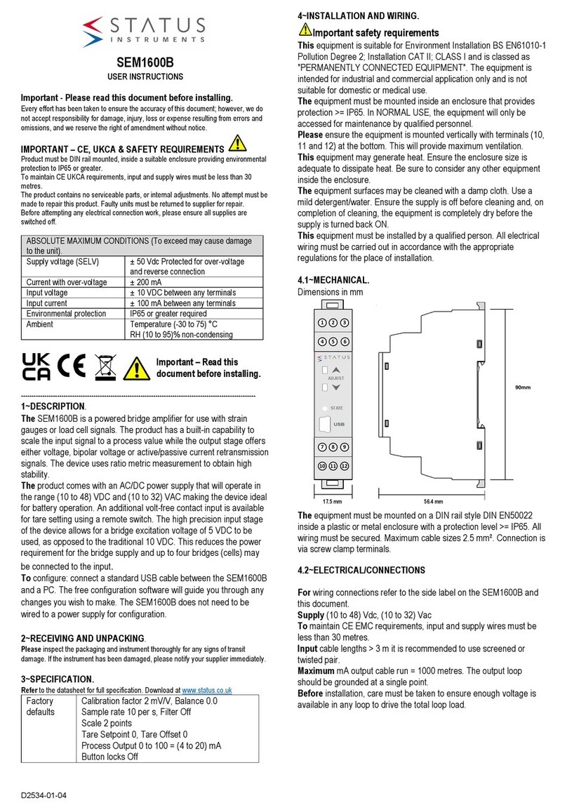
Status Instruments SEM1600B User manual
Status Instruments
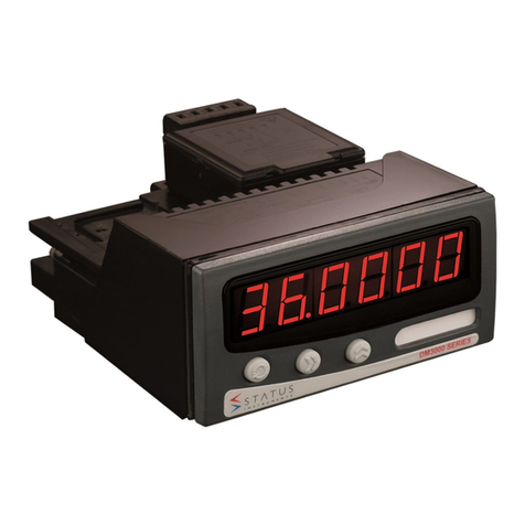
Status Instruments DM3600A User manual
