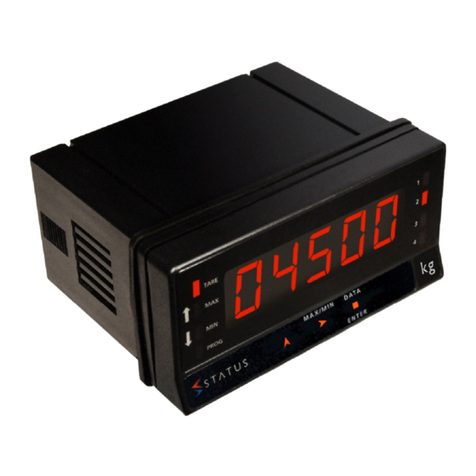
Status Instruments DM4000U User manual

Whilst every effort has been taken to ensure the accuracy of this document, we accept
no responsibility for damage, injury, loss or expense resulting from errors or
omissions, and reserve the right of amendment without notice.
This document is issued by Status Instruments Ltd and may not be reproduced in any
way without the prior written permission of the company.
52-314-2063-03
DM4000U
SMART
INDICATOR
August 2003
Page 1

CONTENTS
GETTING STARTED
1.0 INTRODUCTION 3 - 5
2.0 UNPACKING 6
INSTALLATION
3.0 WIRING 7 - 24
USER GUIDE
4.0 PROGRAMMING 25 - 67
5.0 OPERATION 68 - 73
Appendix A FITTING OF LEGEND ID 74
Appendix B SPECIFICATION 75 - 79
Appendix C TROUBLESHOOTING 80 - 81
Appendix D MAINTENANCE 82
Appendix E USER COMMUNICATION SOFTWARE 83 - 92
Index 93 - 94
Page 2

GETTING
STARTED
Page 3

1.0 INTRODUCTION
This instrument is auniversal digital indicator which supports awide range of input
types. Agreat advantage with this unit is its ability to adapt to awide variety of
applications. Acomprehensive set of programming menus allow the instrument to be
entirely re-configured from the keypad.
The diagram below identifies features on the front panel.
Page 4

The diagram of the rear panel below shows the slot positions for all electrical
connections.
There are two output slots into which the user may fit arange of options, including
relays, current re-transmission and voltage output boards. In addition there is also a
communications board slot allowing up to 30 units to be directly networked together
to ahost computer.
Aschematic of the unit showing internal power supplies and possible options is
shown below
Page 5

2.0 UNPACKING
Please inspect the instrument carefully for signs of shipping damage. The packaging
has been designed to afford maximum protection, however, we can not guarantee that
undue mishandling will not have damaged the instrument. In the case of this unlikely
event, please contact your supplier immediately and retain the packaging for our
subsequent inspection.
Check that the following items are included with the instrument. Note that if there are
output options included there will be additional connectors.
Page 6 SG4-2069-04

INSTALLATION
Page 7

SAFETY INFORMATION
THIS SECTION FOR USE BY COMPETENT PERSONNEL ONLY
•WARNING READ SAFETY INFORMATION BELOW BEFORE
INSTALLATION
•WARNING Hazardous voltages may be present on the terminals -the
equipment must be installed by suitably qualified personnel
and mounted on an enclosure providing protection to atleast
IP20.
•ISOLATION The power supply terminals and associated internal circuitry
are isolated from all other parts of the equipment in
accordance with BS EN61010-1 for connection to aCategory
II supply (pollution degree 2)
Functional isolation (500v max) is provided between input
and output circuits, and between inputs and communications
(where fitted).
Any terminals or wiring connected to the input, output or
communications terminals which are accessible in normal
operation must ONLY be connected to signals complying
with the requirements for Safety extra low voltage (SELV)
circuits.
•WARNING If not installed in accordance with these instructions,
protection against hazards may be impaired
•Installation overvoltage category -2(as per BS EN61010-1)
•(If this equipment is to be used in environments with overvoltage category 3,
transient suppressors should be installed on wiring greater that 50VAC or
75VDC).
•The Mains supply to the equipment must be protected by a1Amp fuse and a
suitable switch or circuit breaker which should be near the equipment.
•The equipment contains no user serviceable parts.
Page 8

MECHANICAL INSTALLATION
When installing the instrument into the panel, the following dimensions should be
taken into account.
The unit is held in the Panel by two metal clamp bars, on diagonally opposite corners,
fitted from the rear. Agasket is available, and should be fitted wherever sealing of the
instrument is required. See diagram below.
The maximum panel thickness is 3.5mm with agasket and 4.5mm without. The gasket
has aself adhesive side which should be stuck to the panel around the cutout. The
instrument may then be inserted and tightened against the gasket to form aseal. The
panel should be clean and smooth for the seal to be effective.
Page 9

INSTALLATION
POWER SUPPLY
3.0 WIRING
This section describes how the instrument should be wired for the Power Supply,
Input Sensor or any Output options that may be fitted. All connections are made to
three or five way sockets which are removable for ease of wiring.
Installation should be undertaken in accordance with relevant sections of
BS6739 -British Standards code of practice for "Instrumentation in Process
Control Systems: Installation design and practice".
See important safety information on page 8
3.1 POWER SUPPLY
The Power supply rating will be
indicated on the top of the instrument.
Ensure that this is correct for the
voltage that is to be connected. If
there is adifference, refer to Service
Manual for details of power supply
adjustment.
Note that the power supply socket has
had polarisation keys fitted to prevent
insertion into any other plug at the rear
of the instrument.
The connection is made as shown.
Ensure that no bare wire protrudes from
the rear of the power connector risking
ashort circuit.
Page 10

3.2 WIRING PRECAUTIONS
The unit can accept avariety of sensor inputs, some of which produce very small
voltages. Therefore it is advisable to adhere to the following rules of good installation
pratice.
•Do not install close to switchgear, electromagnetic starters, contactors, power
units or motors.
•Do not have power or control wiring in the same loom as sensor wires.
•Check power supply voltage is the same as printed on the label attached to the
unit.
•Check wires (especially the power supply voltage wires) are not loose before
switching on the unit.
•Use screened cable for sensor wiring with the screen earthed at one end only.
•Follow the wiring instructions in this manual
3.3 SENSOR CONNECTIONS
All sensor connections are made via the five way socket at the rear of the unit as
shown below.
INSTALLATION
SENSOR CONNECTIONS
Page 11

All sensor connections are summarised in the diagram below.
3.3.1 DC VOLTAGE INPUTS
The unit has two individual voltage inputs. One supports millivolt inputs (up to
100mV ), and the other, voltage inputs up to 10 volts.
If the voltage input to be measured is to be no greater than 100mV it is connected to
the millivolts input. If the signal is less than 10 volts but greater than 100mV, it is
connected to the Voltage input. Any voltages greater then 10 volts may still be
measured, but must be divided down first. Each of these cases is discussed in more
detail below.
3.3.1.1 MILLIVOLTS INPUT
This input accepts signals up to
+/-100mV in normal operation. The
signal source must be connected to
pins 4and 5as shown opposite.
INSTALLATION
SENSOR CONNECTIONS Page 12

3.2.1.2 VOLTAGE INPUT
This input pin can take voltages up
to 10 volts. The signal should be
connected between pins 3and 5as
indicated.
3.2.1.3 VOLTAGES GREATER THAN 10 VOLTS
In order for these to be measured correctly, it is necessary to connect some simple
external circuitry outside the unit to divide down the voltage to anominal maximum of
10volts. This is done using aresistor divider chain as shown in the diagram below.
The choice of resistors are given as the nearest preferred values to those calculated in
the equations for R1 and R2 below. It is possible to correct for any errors in the
divide down chain by making R2 atrimmer, or correct by adjustment of scale range.
Care must be taken to insulate any high voltages to protect from electric shocks or
damage to any other equipment.
SENSOR CONNECTIONS
INSTALLATION
Page 13

3.2.2 CURRENT INPUTS
There are two types of current measurement possible, the first type measures the
current of an external loop, that is, acurrent that has been generated from an external
power supply, or from another instrument. The second type measures current
generated from the units own 20V excitation supply. Before connecting up acurrent
input it is important to establish which one of these two groups apply.
3.2.2.1 CURRENT MEASUREMENT OF AN
EXTERNALLY GENERATED LOOP
In order to measure the current in an
externally generated loop, it is
necessary to insert a resistor
in-circuit and use the instrument to
measure the resultant voltage drop.
Note that the instrument will need to
be configured as a1-5V input and not
a4-20mA input; this is described later
in the programming section. The
diagram shows the necessary
connections.
3.2.2.2 CURRENT MEASUREMENT OF AN
INTERNALLY GENERATED LOOP
The instrument has an excitation
supply which can be used for
generating acurrent loop. If this is
used, the circuit is connected in the
following way. Note that the current
input has an internal impedance of 50
ohms.
INSTALLATION
SENSOR CONNECTIONS Page 14

3.3.3 THERMOCOUPLE INPUTS
Thermocouples are simply connected to the
millivolt input as shown opposite. The cold
junction compensation is performed by the
integral sensor at the rear of the unit or by a
programmable cold junction value. For best
accuracy, it is important that the rear plate is
fitted to prevent draughts causing
temperature differences between the cold
junction sensor and the thermocouple
connection with the device.
3.3.4 Pt100 RESISTANCE TEMPERATURE
DETECTORS (RTDs )
These detectors are for platinum
resistance inputs (Pt100) to BS1904 or
DIN 43760 three wire. RTDs should be
connected using three identical wires in
order that measurement errors due to lead
wire resistances can be eliminated. The
connections should be made as shown in
the diagram opposite.
If it is necessary to use atwo wire
sensor, then it should be connected
across pins 2and 4, with alink added
between pins 4and 5. It must be noted,
however, that this configuration will suffer
from inaccuracies due to the total series
resistance of the wiring.
SENSOR
INSTALLATION
Page 15

3.3.5 TRANSDUCER BRIDGE INPUT
Atransducer bridge requires two sets of connections. Apower supply and bridge
output. The bridge output is treated as amillivolts signal and connected between pins
4and 5as in the diagram below.
Note that the power supply could be from the units bridge excitation output option or
an external power supply.
INSTALLATION
SENSOR CONNECTIONS Page 16

3.4 WIRING THE OUTPUT OPTIONS
This section applies to optional outputs fitted to the instrument. There are four types
of output option available; Change-Over Relay, Dual Relay, Current Retransmission
and Programmable voltage Output. These options may be fitted to either slot in any
combination.
There is, however, arestriction when using Programable Voltage Output with the
Current Retransmission card or another Voltage Output. The combined maximum
current should not exceed 50mA; the supply capacity of the Output options. Another
consideration with apair of analogue output options (Voltage or Current )is that
although there is 500V *isolation from the Input, there is no isolation between output
slots.
*See safety information on page 8
3.4.1 RELAY OUTPUTS, option 1and 2
There are two types of relay outputs available, Dual relay and Change-Over relay. The
dual relay board has two independent contacts sharing the same common.The
Change-over relay has asingle contact with aNormally Open and Normally Closed
output available. The power-off state of the Dual Relay is normally closed, but may
be changed, if required, by modifying hardware links on the board.
It is recommended that aproprietary suppressor network is fitted as close as possible
to the inductive load. DC inductive loads should also have areverse biased diode
connected as shown.
RELAY OUTPUT
INSTALLATION
Page 17

The contact states both these types of relays are summarised in the table below.
If the current to be switched is very low (<100mA) the varistors on the relay board
may need to be removed.
RELAY OUTPUT
INSTALLATION
Page 18

3.4.2 Current Output (Retransmission), option 03
The Current output board can support current loops generated from an external
power supply, or generate aloop source from the instrument itself. Both of these
cases are shown in the diagrams below.
Note that connecting directly across pins 1& 3may cause damage to the
output card.
The instrument may be used as avoltage output by connecting asuitable resistor
between pins 1and 2.
For example by placing a250 ohm resistor across pins 1and 2, and setting the output
board to 4-20mA the voltage output will produce avoltage between 1and 5volts.
CURRENT OUTPUT
INSTALLATION
Page 19

3.4.3 Voltage Output (Bridge Excitation ),option
04
There are two options. Either aprogrammable 2to 20 volt output or afixed 24 volt
output. The connections for both cases are shown below.
INSTALLATION
VOLTAGE OUTPUT Page 20
Table of contents
Other Status Instruments Measuring Instrument manuals

Status Instruments
Status Instruments DM3600A User manual

Status Instruments
Status Instruments DM650HM User manual

Status Instruments
Status Instruments SEM1620 User manual

Status Instruments
Status Instruments SEM1600B User manual
Status Instruments
Status Instruments DM4500U User manual
Status Instruments
Status Instruments DM3600U User manual
Popular Measuring Instrument manuals by other brands

Fluke
Fluke 945 user manual

gaskatel
gaskatel Mini-HydroFlex user manual

Macherey-Nagel
Macherey-Nagel NucleoSpin RNA Clean-up XS user manual

EDT directION
EDT directION QC355TX user manual

STIEBEL ELTRON
STIEBEL ELTRON SOM WMZ SOL Operation and installation

Agilent Technologies
Agilent Technologies Flow Tracker 1000 Series User information