Steadicam Volt User manual

LIT-817001, Rev B
Steadicam®Volt™User Guide

Table of Contents
1 Introduction
2 Components
Volt operating
7 Let’s get started!
8 Choosing sides
9 Balance
11 Power on
15 Operating
19 Settings
Volt Installation
25 Types of installations
29 Installation of Volt complete kit
35 Installation of Volt onto bare gimbals
43 Flip Button
45 Motor belts
Gimbal upgrades
51 Archer/Archer2 gimbal upgrade
53 Archer/Archer2 gimbal balancing
55 Ultra2, Shadow, Clipper gimbal upgrade
59 PRO CineLive, PRO CineHD gimbal upgrade
63 U2, Shadow, Clipper, PRO gimbal balancing
Troubleshooting
67 Troubleshooting checklist
68 Frequently asked questions
73 Electronics
75 Contact Tiffen
TIP: This table of contents is hyperlinked to navigate you through the respective sections. Page references
throughout the manual are also linked to the appropriate page. To return to the table of contents, just click
on the page number at the bottom of any page. Easy.

1
The Steadicam®Volt™
Working with the sled’s inertia and neutral balance, the Volt generates an “articial bottom-heaviness” to
keep the horizon level and headroom stable. With Volt, the operator can concentrate on precise framing,
timing, navigating, and other more interesting aspects of operating.
The strength of the roll and tilt assistance may be individually ne-tuned to suit the operator’s
preferences, and easily adjusted for different shots. The assistance can feel like operating a sled with a
very long drop time – easy to tilt or roll – to full gyro-simulation, with the sled locked hard to the horizon
in roll, or tilt, or both.
Because the sled is always balanced neutrally top-to-bottom, all pendular effects from acceleration and
deceleration are eliminated. Plus, there is no re-balancing needed when switching to low mode!
Trunnion motor
and belt
The Volt also allows behaviors that were impossible
before. Like “friction mode” which emulates a uid
head with tilt hold and a xed horizon, bringing
you new control options for each and every shot.
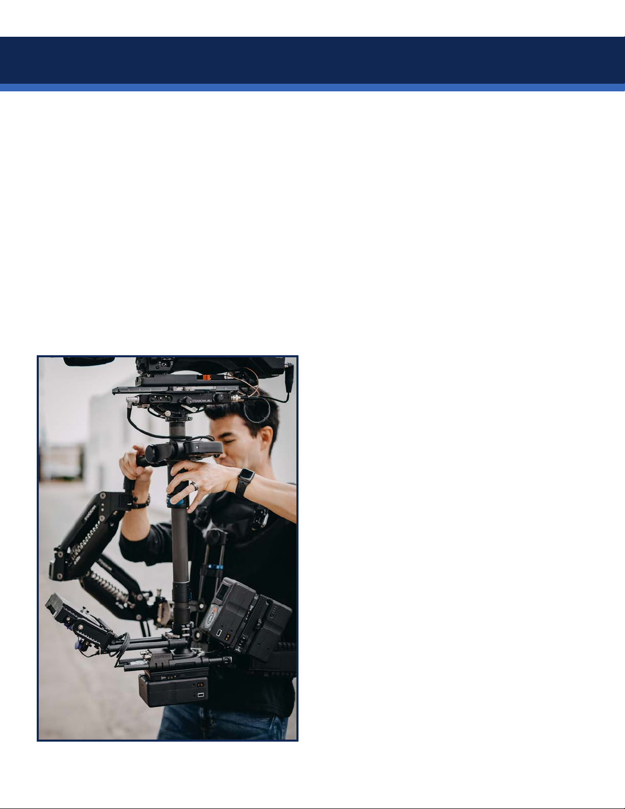
In use, the Volt is completely transparent to the
operator, and it feels exactly like regular Steadicam
operating – with perfect horizons. The operator is
always in full and direct control of framing, and can
easily override the Volt’s assistance.
This user guide is organized to get you up and
running quickly; with components and operating
up rst, then how-to install the popular complete
M-2 Volt gimbal kit onto a sled. Further back, we
show step-by-step installation of Volt components
onto any gimbal, and nally, the factory upgrade
steps for older gimbals, should you be so inclined.
Welcome to the future of professional Steadicam
operating!
Introduction

2
Trunnion pulley
Handle pulley
Trunnion motor
and belt
Pan encoder
Pan encoder ring inside
Steadicam®Volt™shown on M-2™gimbal
Main power/control input
& encoder jack
Handle motor
and belt
Mode LED (green)
Gimbal button
Power LED (blue)
Trunnion screw access
Invert button access
Components
Gimbal clamp lever
1.5” post
1.75” post
1.58” post
M-2™gimbal post spacers Thumb button

3
Nose box rods
Power and Mode LEDs
Run/pause switch
Steadicam®Volt™Control Box
Main power switch
Level trim button
Power input jack from sled
12V power
Display jack
(RESERVED)
Main power/control output to
Volt gimbal motors
Roll strength dial
Tilt strength dial
Damping adjuster
MDR-3 mount
Padded dock insert
specic for your gimbal
NOTE: The LEMO connectors rotate up to 90˚ in the control box chassis to allow you more options when running cables
with right-angle connectors.
Components

4
Steadicam®Padded Dock
The new dock
The padded dock is designed to protect the Volt electronics as well as make docking and balancing
easier. The low-prole design ensures nothing contacts the Volt gimbal motor assembly when docked,
and the “over-center” arm swings into place to secure the sled. Docking on the gimbal also reduces
shock loads on your gimbal bearings. You’ll enjoy a low, primary balance stud on the side, which is
barely higher than your gimbal handle, making it a simple task to lift for balancing regardless of the sled
build. And the dynamic balance stud is adjustable in length to clear your rig for endless spins.
MDR-3 mount
Dynamic balance stud
Tool holder
Arm holder
Padded dock insert
specic for your gimbal
Static balance stud
Over-center hook Hook lock lever
Dock tilt lock knob
Stand lock knob
Components

5
Included with Steadicam®Volt™M-series gimbal kit
• M-2 gimbal with Volt Motor Assembly, internal encoder, pulleys and belts installed and tested
• Volt Control Box (mustache box)
• Gimbal cable, short (817-0135)
• M-2 gimbal post spacers for 1.5”, 1.58” and 1.75” posts
• Padded Dock, insert and balance studs for gimbal, and case (817-7980)
Included with Steadicam®Volt™upgrade kit for M-1
• Volt Gimbal Motor Assembly, pulleys, belts and hardware
• Volt Control Box (mustache box)
• Pan encoder assembly and pan encoder ring for gimbal
• Gimbal cable, short (817-0135)
• Padded Dock, your choice of balance studs, and case (817-7980)
• Nose box mounting rods
• Spare adhesive tapes for pan encoder ring
Also included with upgrade kits for other gimbals
• Volt compatible yoke and mounting kit for your gimbal
• Blue pin wrench for your gimbal
• Mounting options you selected
• Upgrade kit details begin on page 51
Tools required for installations
• Blue “whale” gimbal tool for your gimbal.
• Imperial Allen key set for install and belt adjustment.
• Flat screwdriver for nose box rods.
• Loctite®222™ for post top screws and upgrade kits.
Components
CAUTION: The external pan encoder ring included in many kits is a precisely manufactured magnet and should NOT be
exposed to strong external magnetic elds before or after installation.
Pan encoder ring
Upgrade kits available
for these gimbals:
Archer
Clipper
Shadow
Ultra2
M-1/M-2
PRO CineLive
PRO CineHD
Betz
Check with Tiffen for the latest
list of available upgrade kits.

Phone: 818-843-4600 Fax: 818-845-1929
2815 Winona Ave., Burbank, CA 91504
®
THIRD ANGLE
PROJECTION
SCI-B012B1230
8X
817-7952
2X
REVISIONS
BY
REV.
ECO
DESCRIPTION
DATE
APPROVED
R.ORF
A
180038
PRODUCTION RELEASE
04-20-2018
ITEM
NO.
PART NUMBER
DESCRIPTION
QTY.
1
817-7952
MTG BRACKET
2
2
SCI-B012B1230
SCW, 8-32 x 3/8 BUT HEX 18-8 SS BLK TEFLON
8
D
C
B
A
A
B
C
D
1
2
3
4
5
6
7
8
8
7
6
5
4
3
2
1
THE INFORMATION CONTAINED IN THIS
DRAWING IS THE SOLE PROPERTY OF
THE TIFFEN COMPANY. ANY
REPRODUCTION IN PART OR AS A WHOLE
WITHOUT THE WRITTEN PERMISSION OF
THE TIFFEN COMPANY IS PROHIBITED.
PROPRIETARY AND CONFIDENTIAL
DIMENSIONS ARE IN INCHES AND
APPLY AFTER PROCESS FINISH
TOLERANCES:
FRACTIONAL
1/64
ANGULAR: MACH
1
BEND
1
.X
.1"
.XX
.01"
.XXX
.005"
.XXXX
.0005"
CONCENTRICITY: .003 T.I.R.
BREAK SHARP EDGES: .005 - .010
MACHINED FILLETS: .003R - .005R
MACHINE FINISH 63 RMS
INTERPRET DRAWING PER
ANSI Y14.5 2009
DRAWN
CHECKED
ENGINEER
COMMENTS:
DATE
NAME
TITLE:
SIZE
B
DWG. NO.
REV
WT: 0.103
SCALE: 1:2
UNLESS OTHERWISE SPECIFIED:
A
MW
R.ORF
R.ORF
02/13/18
06-11-18
2/13/2018
KIT, MDR-3 MTG
SHEET 1 OF 1
817-7960
DO NOT SCALE DRAWING
FILE NAME:
817-7960
*
NOTES: UNLESS OTHERWISE SPECIFIED
Phone: 818-843-4600 Fax: 818-845-1929
2815 Winona Ave., Burbank, CA 91504
®
THIRD ANGLE
PROJECTION
SCI-B024S1210
4X
817-7944
1X
SCI-A016S1220
2X
SCI-B012S1210
2X
817-7940
2X
REVISIONS
BY
REV.
ECO
DESCRIPTION
DATE
APPROVED
MW
A
190020
PRODUCTION RELEASE
02/15/19
ITEM
NO.
PART NUMBER
DESCRIPTION
QTY.
1
817-7944
ROD MOUNT
1
2
817-7940
ASSY, L-CLAMP
2
3
SCI-A016S1210
SCW, 6-32 x 1/2 SHC HEX
2
4
SCI-B012S1210
SCW, 8-32 x 3/8 SHC HEX
2
5
SCI-B024S1210
SCW, 8-32 x 3/4 SHC HEX 18-8 SS
4
D
C
B
A
A
B
C
D
1
2
3
4
5
6
7
8
8
7
6
5
4
3
2
1
THE INFORMATION CONTAINED IN THIS
DRAWING IS THE SOLE PROPERTY OF
THE TIFFEN COMPANY. ANY
REPRODUCTION IN PART OR AS A WHOLE
WITHOUT THE WRITTEN PERMISSION OF
THE TIFFEN COMPANY IS PROHIBITED.
PROPRIETARY AND CONFIDENTIAL
DIMENSIONS ARE IN INCHES AND
APPLY AFTER PROCESS FINISH
TOLERANCES:
FRACTIONAL
1/64
ANGULAR: MACH
1
BEND
1
.X
.1"
.XX
.01"
.XXX
.005"
.XXXX
.0005"
CONCENTRICITY: .003 T.I.R.
BREAK SHARP EDGES: .005 - .010
MACHINED FILLETS: .003R - .005R
MACHINE FINISH 63 RMS
INTERPRET DRAWING PER
ANSI Y14.5 2009
DRAWN
CHECKED
ENGINEER
COMMENTS:
DATE
NAME
TITLE:
SIZE
B
DWG. NO.
REV
WT: 0.163
SCALE: 2:1
UNLESS OTHERWISE SPECIFIED:
A
MW
R.ORF
R.ORF
10/11/18
2/15/19
2/15/19
ASSY 60X15mm ROD MOUNT
SHEET 1 OF 1
817-7945
DO NOT SCALE DRAWING
FILE NAME:
817-7945
*
NOTES: UNLESS OTHERWISE SPECIFIED
Phone: 818-843-4600 Fax: 818-845-1929
2815 Winona Ave., Burbank, CA 91504
®
THIRD ANGLE
PROJECTION
KNB-140044
2X
817-7954
REVISIONS
BY
REV.
ECO
DESCRIPTION
DATE
APPROVED
R.ORF
A
180038
PRODUCTION RELEASE
04/20/18
R.ORF
B
180138
RE-DESIGN
10/11/18
MW
C
190020
ROLLBACK TO REV. A
02/15/19
ITEM NO.
PART NUMBER
DESCRIPTION
QTY.
1
817-7954
ROD MOUNT
1
2
KNB-140044
KNOB, T, 10-32 X .39
2
ASSY, 60 X 15 mm ROD MOUNT
C
DO NOT SCALE DRAWING
817-7955
SHEET 1 OF 1
4/20/18
2/15/19
4/20/18
R.ORF
R.ORF
UNLESS OTHERWISE SPECIFIED:
SCALE: 1:2
WT: 0.000
REV
DWG. NO.
A
SIZE
TITLE:
NAME
DATE
COMMENTS:
ENGINEER
CHECKED
DRAWN
INTERPRET DRAWING PER:
ANSI Y14.5 2009
DIMENSIONS ARE IN INCHES AND
APPLY AFTER PROCESS FINISH
TOLERANCES:
FRACTIONAL
1/64
ANGULAR: MACH
1
BEND
1
.X
.1"
.XX
.01"
.XXX
.005"
.XXXX
.0005"
BREAK SHARP EDGES: .005 - .010
MACHINED FILLETS: .003R -.005R
MACHINE FINISH 63 RMS
THE INFORMATION CONTAINED
IN THIS DRAWING IS THE SOLE
PROPERTY OF THE TIFFEN
COMPANY. ANY REPRODUCTION
IN PART OR AS A WHOLE
WITHOUT THE WRITTEN
PERMISSION OF THE TIFFEN
COMPANY IS PROHIBITED.
4
3
2
1
FILE NAME:
817-7955
NOTES UNLESS OTHERWISE SPECIFIED
*
R.ORF
PROPRIETARY AND CONFIDETIAL
Phone: 818-843-4600 Fax: 818-845-1929
2815 Winona Ave., Burbank, CA 91504
®
THIRD ANGLE
PROJECTION
4X SCI-B010F1210
817-7911
4X SCI-B012S1210
2X SCI-F010S1210
2X SCI-A012S1210
817-7912
REVISIONS
BY
REV.
ECO
DESCRIPTION
DATE
APPROVED
MW
A
180060
PRODUCTION RELEASE
05/11/18
ITEM NO.
PART NUMBER
DESCRIPTION
QTY.
1
817-7912
MTG PLATE, VOLT
1
2
817-7911
DOVETAIL PLATE
1
3
SCI-F010S1210
SCW, 1/4-20 x 5/16 SHC HEX
2
4
SCI-B010F1210
SCW, 8-32 x 5/16 F82° HEX
4
5
SCI-B012S1210
SCW, 8-32 x 3/8 SHC HEX
4
6
SCI-A012S1210
SCW, 6-32 x 3/8 SHC HEX
2
D
C
B
A
A
B
C
D
1
2
3
4
5
6
7
8
8
7
6
5
4
3
2
1
THE INFORMATION CONTAINED IN THIS
DRAWING IS THE SOLE PROPERTY OF
THE TIFFEN COMPANY. ANY
REPRODUCTION IN PART OR AS A WHOLE
WITHOUT THE WRITTEN PERMISSION OF
THE TIFFEN COMPANY IS PROHIBITED.
PROPRIETARY AND CONFIDENTIAL
DIMENSIONS ARE IN INCHES AND
APPLY AFTER PROCESS FINISH
TOLERANCES:
FRACTIONAL
1/64
ANGULAR: MACH
1
BEND
1
.X
.1"
.XX
.01"
.XXX
.005"
.XXXX
.0005"
CONCENTRICITY: .003 T.I.R.
BREAK SHARP EDGES: .005 - .010
MACHINED FILLETS: .003R - .005R
MACHINE FINISH 63 RMS
INTERPRET DRAWING PER
ANSI Y14.5 2009
DRAWN
CHECKED
ENGINEER
COMMENTS:
DATE
NAME
TITLE:
SIZE
B
DWG. NO.
REV
WT: 0.296
SCALE: 1:1
UNLESS OTHERWISE SPECIFIED:
A
MW
R.ORF
R.ORF
5/4/18
06-12-18
5/11/18
KIT, VOLT MDR-3 MOUNT
SHEET 1 OF 1
817-7915
DO NOT SCALE DRAWING
FILE NAME:
817-7915
PRO
NOTES: UNLESS OTHERWISE SPECIFIED
6
Control Box mounting options
Nose box adapter
Ultra2, Shadow, Clipper, Archer
(800-7910)
MDR-3 mount
For any MDR compatible setup
(817-7960)
LWS 60x15 rod mount
Attach to nose box rods
(817-7945)
MDR-3 mount PRO
Dovetail plate included
(817-7915)
LWS 60x15 rod mount
Attach to nose box rods
(817-7955)

7
Before you begin
The two major components of Steadicam® Volt™, the motor assembly and the control box, contain
advanced sensors and electronics. Each may be mounted left or right, to optimize the controls for your
operating, but you must be aware of the differences these choices present for the Volt electronics.
• The external Volt control box may be mounted to face regular or goofy-sided operators. If your
knobs are to the right of the sled (regular operator), you’ll align the gimbal handle to the rear of the
post on power up. If your knobs are to the left of the sled (goofy operator) you’ll align the gimbal
handle to the front of the post on power up. See page 11 for more info.
Right knobs = REAR, Left knobs = FRONT
• Similarly, the Volt motor assembly may be mounted left or right on the gimbal. This has no effect
on powering up, but if you’re installing the Volt yourself, be aware that left side is default mode and
right side mounting requires pressing the internal “ip” button once to reorient the Volt sensors. See
page 43 to learn about the ip button. If the Volt was installed at your dealer, the ip procedure will
have been performed already.
We strongly encourage professional installation of the Volt components onto your system by an
authorized dealer, but installation instructions for a variety of upgrade paths are provided in this manual.
For more information visit tiffen.com/steadicam/voltsystem/ or contact your Tiffen dealer.
Let’s get started!

8
Notes about left or right side motors
The Volt gimbal motor assembly, casually referred to as the hockey stick, may be mounted to either
side of the gimbal yoke. In general, regular operators prefer to mount it to the left and goofy operators
mount it to the right. This allows maximum viewability of the monitor and places the gimbal button
conveniently near your thumb. However, broadcast users may wish to test t their zoom controller onto
the handle to ensure access to the gimbal button. Also, keep in mind your rest position may need to
change if the Volt gimbal motor assembly contacts your body.
RIGHT side mount
(typically goofy)
LEFT side mount
(typically regular)
Choosing sides

Then, change the balance to be completely
neutral top-to bottom. It should hold any
post angle and not rotate.
TIP: For a refresher on dynamic balancing,
see Section One of The Steadicam
Operator’s Handbook.
Balance the sled with a normal to long drop
time. BOTH static and dynamic balance are
important here. You know how to dynamic
balance, right?
NOTE: You may wish to temporarily remove the
gimbal cable while dynamic balancing to allow
multiple rotations.
9
Neutral balance
In order for the motors to exert maximum balancing assistance to the roll and tilt axes, we balance the
sled completely neutral. No drop time at all! This also eliminates any pendulum effect when accelerating
or stopping the sled. Static and dynamic balance are now even more critical, so panning the camera will
not create diagonal forces and the sled can easily be held at any angle without rotating.
TIP: Build your rig with more pan inertia (monitor and batteries extended) to increase stability in the pan
axis, which the Volt motors do not affect. This will reduce unwanted panning motions in your image.
Balance

10
Balance
Make sure the sled does not pan when holding
a tilt. If so, a tiny adjustment to your side-side
balance should correct this.
Otherwise, go back and re-check your dynamic
balance.
When changing accessories above the gimbal,
like lenses or lters, re-balance on the dock
with a normal drop time and then go fully
neutral again.
TIP: When you change anything ABOVE
the gimbal and re-balance at the top stage,
dynamic balance is maintained!

11
Powering up
Adding the Steadicam® Volt™ to your system requires an extra step when powering up, and when picking
up your sled. First, you’ll align the pan encoder while powering on, and later you’ll run the system when
you want the Volt motors active. It’ll become second nature, but pay close attention while you’re getting
started for best results.
NOTE: Any sled with internal Volt controls, such as an M-2, will always align the gimbal handle with the
REAR of the post, no matter which side of the top stage the built-in knobs are installed.
Power on
Make sure the power switch is in the OFF
position and plug in the power cable from
your sled to the Volt control box.
NOTE: If you use an aftermarket power cable,
conrm the polarity is correct. Volt is protected
against reverse voltage, but won’t work very
well without power.
Plug in the Volt gimbal cable and wrap a
couple of loops around the post as needed to
control any slack.
NOTE: The Volt control box will not power up
without the gimbal cable properly connected.

12
Power on
Before powering on the system, double check
that the PAUSE switch is engaged.
TIP: Consider using the Roll, Damping and Tilt
settings shown here as a starting point. More
suggestions on page 21.
IF the control box is mounted for regular
operators (knobs on the RIGHT) align the
gimbal handle with the REAR of the post and
simultaneously power on the Volt. Wait 2.5sec
while the system registers the pan encoder
position.
The blue LEDs glow.
You’ll do this EVERY TIME you power on the Volt.
IF the control box is mounted for goofy operators
(knobs on the LEFT) align the gimbal handle
with the FRONT of the post and simultaneously
power on the Volt. Wait 2.5sec while the system
registers the pan encoder position.
The blue LEDs glow.
You’ll do this EVERY TIME you power on the Volt.

13
Power on
Pick up the sled on your arm or use the
padded dock’s balance pin.
With the post vertical, ip the pause switch to
ON and the Volt becomes active.
The green LEDs glow.
You should now feel the horizon assistance
and articial bottom-heaviness of normal
mode.
The Volt only needs to have the post encoder
aligned when powering on.
Pausing and activating the Volt can be toggled
with the handle in any orientation.
If you do power down, remember to align the
handle again when powering back up.
Powering on the system sets the roll and tilt
trims to default horizon for a vertical post
with level tilt head.
In the next section, we’ll explore trimming
and modes.

15
Operating with the Steadicam®Volt™
The best thing about adding this tool to your system is that you’re still operating a mechanical
stabilizer, and using your skills and years of experience to craft each shot. Here are some tips on how to
optimize the Volt, starting with trimming the post angle and the two operating modes. We’ll adjust the
control box dials later.
DO NOT TRIM with your top stage
balance like we used to...
Leave the sled in perfect neutral
balance at all times!
Operating
To trim, tilt the sled to any angle and SHORT-
press the gimbal handle (thumb) button. The
new trim angle is set immediately.
In normal mode, the articial bottom-heaviness
will return the sled to THIS angle.
This can be done on the y, during the shot - a
huge advantage to your operating.

16
Operating
The two operating modes are toggled with a
LONG press of the gimbal button.
In normal mode, the sled will return to your
trimmed tilt angle, simulating a normally balanced
Steadicam sled.
Normal mode is always default and displays
SOLID green LEDs.
The second mode is called the “Friction mode”
and displays PULSING green LEDs.
In friction mode, the sled will remain tilted
where the operator places it and require force to
change tilt position.
It’s like having a uid head on your Steadicam!
Using your sled’s integrated tilt head maintains
the vertical post, ideal for panning.
First, pause the system, change the tilt and re-
balance the sled.
Then run the Volt and set a new tilt trim by short
pressing the gimbal button.

17
Operating
Should you wish to set the ROLL trim, SHORT-
press the trim button on the control box and
position the sled to the new level position while
the LEDs blink for 5 seconds.
When LED blinking stops, your new horizon
position (or Dutch angle) is now stored in
memory.
To reset the roll horizon to default, LONG-
press the trim button on the control box for 6
seconds until both LEDs on the control box turn
off and pulse back on.
Horizon is now reset.
Any previous TILT trim will be maintained.
Quick low mode is now easier than ever!
When ipping, there is no need to re-balance
because the sled is neutral.
Simply invert the sled and rotate the monitor
for viewability.
NOTE: If you tilt the head, make
sure to set a new trim.
Table of contents
Other Steadicam Camera Accessories manuals

Steadicam
Steadicam Steadimate-S User manual

Steadicam
Steadicam G-70x Arm User manual

Steadicam
Steadicam Ultra2 User manual

Steadicam
Steadicam ARCHER2 User manual

Steadicam
Steadicam Merlin 2 Manual instruction

Steadicam
Steadicam Ultra2 User manual

Steadicam
Steadicam M-1 User manual

Steadicam
Steadicam MERLIN2 User manual

Steadicam
Steadicam Merlin Arm & Vest Technical manual

Steadicam
Steadicam G-70x User manual