Steadicam Ultra2 User manual


1
This guide assumes the operator is
familiar with the original Ultra features
and benefits, as well as general Steadicam
principles and practice. We will limit this
guide to what’s new in the Ultra2sled
(and there’s still a lot to discuss!).
The original Ultra Operator’s Guide and
the Ultra Manual are available online at
www.steadicam.com.
Ultra2Quickstart Guide
Version 1
Topics:
Camera mounting stage mechanics and adjustment
Stage PCB boards, connectors, switches, and pots
Telescoping post clamps and adjustments
Monitor mounting
Slanted F-bracket
Ultra2gimbal centering (how to use the blue whale!)
Ultra2gimbal remote control
Go-to motors and controls
Frameline generator and voltage display adjustments
Ultra2 artificial horizon sensor and adjustments
PowerCube batteries and chargers
28 or 14 volt operation
Pivoting Ultra2battery mount
Sliding accessory plate
Base electronics and the VDA
Version 12.7.2006 11:16 am

2
Stage mechanics and
adjustments
The dovetail clamp lever has three
positions: forward and locked, 90º for
adjustments, and 60º
back for mounting
or removing the
dovetail plate. A
safety button must be
pushed to move the
lever to the unlocked
position; the same
button holds the
lever fully open,
making flips to low
mode and back a bit
easier. Do not force
the lever backwards
beyond its stop.
Even with a very wide camera, the clamp
lever can always be accessed, but the
safety release button might require a thin
screwdriver.
The Ultra2motorized stage is position
sensing – much like a focus motor system
for a lens. One use of this feature is to set
the stage to the center of travel, both fore
and aft and side to side – great for initial
setups.
The Stage
Mechanics,
Adjustments &
Connectors
The speed and direction of the motors is
set by the switches and thumbwheel pots
on the left (port) side of the nosebox.
Note that the motor direction switches
also have a center-off position, just in
case you are in an odd RF environment
or you don’t want your stage motors to
move. Remember this “function” when a
stage motor stops working between takes!
The electronics in the stage and nosebox
are on “plug and play” circuit boards,
easy to replace if there’s ever a problem.
It’s also easy to access to the inside of the
stage, add or swap stage motors, adjust
the bearings, etc., but that’s beyond the
scope of this quickstart guide.
The stage is easy to adjust. The knob at
the right rear controls fore and aft, and
the two knobs on the side control side-to-
side movement.
Pushing the double pole momentary
switch on the “nosebox” to the “C” side
centers the stage.
Flipping the switch the other way (“L”)
sets the stage to a pre-programmed
position (more about that later.)

3
The stage connectors:
At the rear of the stage, left to right (port side to starboard side):
Camera power connector. 3 pin Lemo, +28, +14, and ground.
HDSDI in. This connector has no connection to the distribution amplifiers or DA’s. BNC
HD component video in. 6 pin Lemo
Standard definition (PAL/NTSC) composite video in. BNC
At the front (nosebox), left to right:
Power for focus motor receiver/amplifiers. 3 pin Lemo (+28, +14, and ground)
Stubby black antenna (no connection, just thought you’d like to know what it was)
Tally light connector (future functions possible)
Nosebox port side:
Pot to adjust Tally sensor sensitivity
Rotary switch to set remote channel (0-8)
Forward, flanking the stage:
Port side:+12VDC (regulated) and video
in. 4 pin HRS.
Starboard side: +14VDC and video out. 4
pin HRS.

4
While we’re at it, the base connectors:
Top center: HDSDI, direct connection to HDSDI connector in stage; no connection to
the video DA’s. BNC. If your video DA fails, you can use this for a direct connection
to the monitor.
Top left: RCA video in/out for a video recorder. The small slide switch sets in or out.
Base Connectors,
Post Clamps &
Low Mode Top right: Video out and +14 VDC. 4 pin
HRS.
Monitor connector: power, component
video, and data line. 8 pin Lemo.
HD component video. 6 pin Lemo
DC Power plug, adjustable +4.5 to +9.5
VDC. Remove plastic cap and use small
screwdriver to adjust. Factory set at 7.2
volts.
At the bottom center is the auxiliary
28 and 14 volt, 3 pin Lemo, good for
powering gyros or other accessories. The
connector can also be used as a power
input connector. You can connect an extra
battery to help power high amperage, 12
to 14 volt cameras like the Panavision
Genesis.
If you are not using the HDSDI and/or
the HD component lines, you may
use them for other purposes, such as a
microphone line down the post or speaker
wires up the post. However, only use the
red or blue component BNC inputs; the
green line shares wiring with the standard
composite BNC input and is connected to
the video distribution amplifier.
Post clamps
The Ultra2’s post clamps are positive
locking. They are either fully open or
closed, and they snap shut with a healthy,
positive click. Do not force the lever
further open.
The clamps are easily adjusted with a
small Allen wrench. Adjust the screws
with the lever closed – just go slowly.
Adjust both screws equally, so the clamp
remains parallel to the housing. If the
screws are over-tightened, the lever may
not open or close.

5
Monitor mounts
There are two monitor mounts on the Ultra2, one on post four
(the bottom post) and one on post three. The two mounts are
identical, and permit a large vertical range of monitor positions.
The 2nd monitor mount can be used for securely mounting a
gyro, recorder, 2nd monitor, etc.
Also for low mode: The safety for the slanted F-bracket has been redesigned for
simplicity and ease of use, with the safety pin centered on the arm post.
Removing the monitor mount and flipping to low mode
Always support the monitor. Loosen the Kipp handle, depress the safety button, and
slide the monitor bracket straight up or down. To replace, engage the monitor bracket
with the dovetail squarely and slide it down until the safety clicks in. Tighten the Kipp
handle. The monitor will be square to the post.
There are two positions for the F-bracket,
one for regular side operating and one
for goofy-foot. Be sure to angle the F-
bracket away from you (about 45 degrees
forward) when standing in the Missionary
position.regular operating
goofy foot operating

6
The gimbal and the remote
The Ultra2 gimbal has been completely
redesigned with higher-precision, high
load bearings. The gimbal body, yoke,
and handle are strong and precisely
registered to each other. The yoke’s new
shape and contoured edges extends the
range of motion without interference and
promotes a better operating grip over a
wider range.
The operator can easily center the gimbal
in the field – useful if you’ve taken apart
the gimbal for cleaning, taken a really
bad bump, etc.
Here’s how:
• Place the gimbal on the docking stud (as
you would for normal balancing), give
yourself a four second drop time, and aim
the camera along a line through the two
bearings in the yoke.
• Balance side to side only, then rotate 90
degrees (aim the camera at the docking
stud) and balance precisely fore and aft.
Do not touch the stage again.
Gimbal, Remote
& Go-To Buttons
• Rotate the sled 90 degrees, so the
camera is again aimed along a line
through the two yoke bearings. If it is
level, great. If not, use the “blue whale”
tool to loosen one of the two end caps
1/10 of a turn or so, and tighten the other
one to the same degree.
• If it gets worse, you
chose the wrong one
to loosen! If it gets
better, keep going
until it is perfect. Do
not rebalance fore and
aft with the stage.
A small warning: do
not over-tighten the
caps against the bearings, as this will
cause binding. Just tighten each cap down
to touch the bearing. If the bearing starts
to bind, just back off one of the two end
caps until the gimbal is free again. The
blue whale tool also makes it easy to take
apart and clean the gimbal if this ever
becomes necessary.
The remote is held in place by two sets
of pins. The forward set of pins slips
into two small holes, and the rear set
of pins are captured in a groove in the
knurled ring.
When returning the remote to the
handle, insert the pins carefully and do
not force anything.
Removing the remote
Whenever you want to hand the
remote off to your assistant (or charge
the remote’s battery), unscrew the
knurled ring.

7
Leave the sled on as you charge the
battery. It takes about XXX(Charge rate
is currently approx 20mA which gives
us an approximate 5Hr charge time for
a dead (nominal 100mAH, 120mAH
typical) battery. Can possibly drop
this down to 1Hr.) hours to charge a
completely discharged remote battery.
When the battery is charging, the green
LED will be on. When the lithium-ion
battery is fully charged, the green light
goes off. Battery life can vary depending
on how often the transmitter is used and
what the storage and operating conditions
for the transmitter are.)
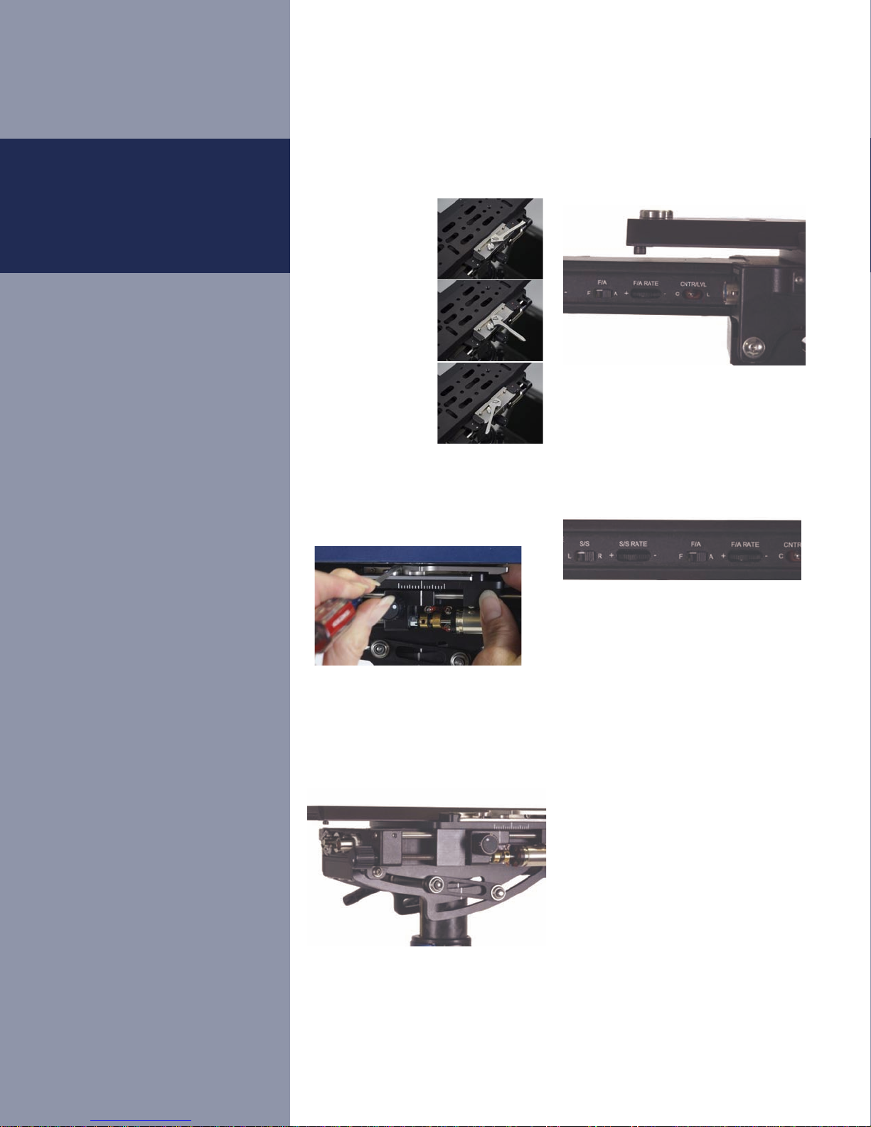
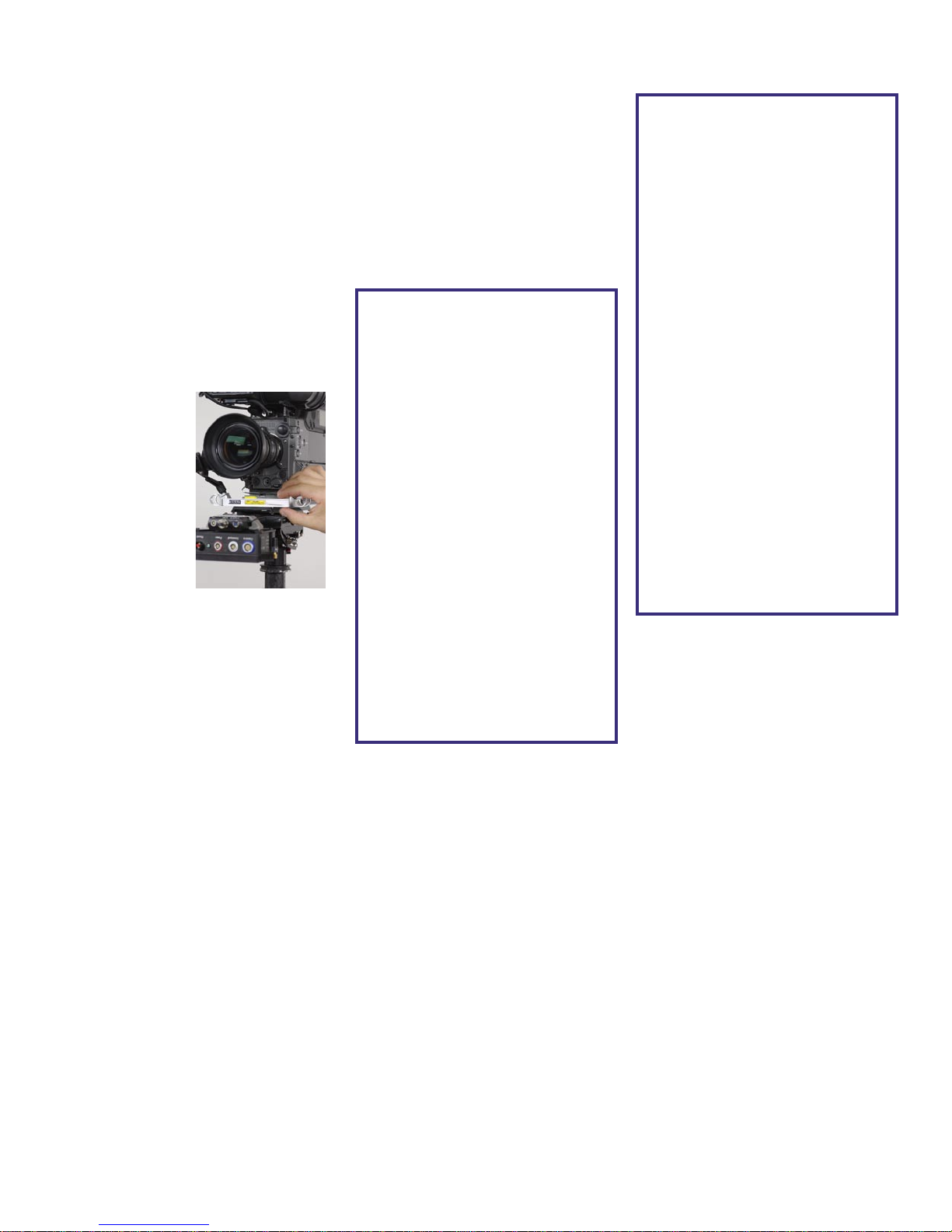
The remote control is ergonomically
designed, and it rotates to any angle
for your comfort, whether you operate
normally or goofy-footed. To angle the
remote, loosen the small set screw in the
curved handle of the gimbal. Orient the
remote by screwing the curved handle
in or out. If the handle is too far in, you
can’t easily remove the remote via the
blue knurled ring, and you might have
to back the handle off one full turn.
Loosening the setscrew and unscrewing
the handle is also how you access the
“tilt” bearings and shaft for cleaning.
“Go-to” Buttons
On the remote control, there are three
“go-to” buttons on one side in addition to
the four original “trim” buttons (as well
as two other “spare” buttons).
The go-to buttons move the stage
to specific marks, defined by the
operator. One position is usually the
nominal balance, and the other two are
programmed for some other part of the
shot. During the shot, the operator (or an
assistant holding the removable remote)
pushes a go to button to move the stage
precisely to a new trim setting. Pushing
the “home” button at any time returns
the stage to the nominal trim. No more
counting revolutions or so many seconds;
the stage moves exactly where you want
it to — and back.
In addition to big tilts and Dutch angles,
you might set a button to “post perfectly
vertical and in dynamic balance,” and use
another button for the nominal trim for
the shot at hand. Or set the three buttons
to roughly account for the movement of
film in some magazines.
Programming the go-to buttons is a snap.
Move the stage to the desired position,
either manually or using the traditional
trim buttons. Then hold one of the go-
to buttons down for three seconds. The
green LED will flash twice, and it’s set.
You can even program any button on
the fly, during the shot, if you have the
mental reserves...
Note that both fore-aft and side to side
positions are programmed via the go-
to buttons. Trimming fore and aft may
slightly alter your precise side to side
balance, or you may want to program
in a severe Dutch angle. You can even
program two or three buttons for the
same trim if you like, so you don’t have
to think about which button to push!
The positions are stored in non-volatile
memory, so changing batteries or turning
off the sled does not erase your presets.
The center go-to button on remote shares
the same preset as the “L” position on the
switch on the nose box. The “L” position
is programmed exactly like the center go
to button on the remote, and the red mode
LED on the nosebox will flash to confirm
programming.
Holding one of the go-to buttons down
for more than six seconds will clear all
programming for that button and make
it non-operational. The green LED will
flash 3 times.
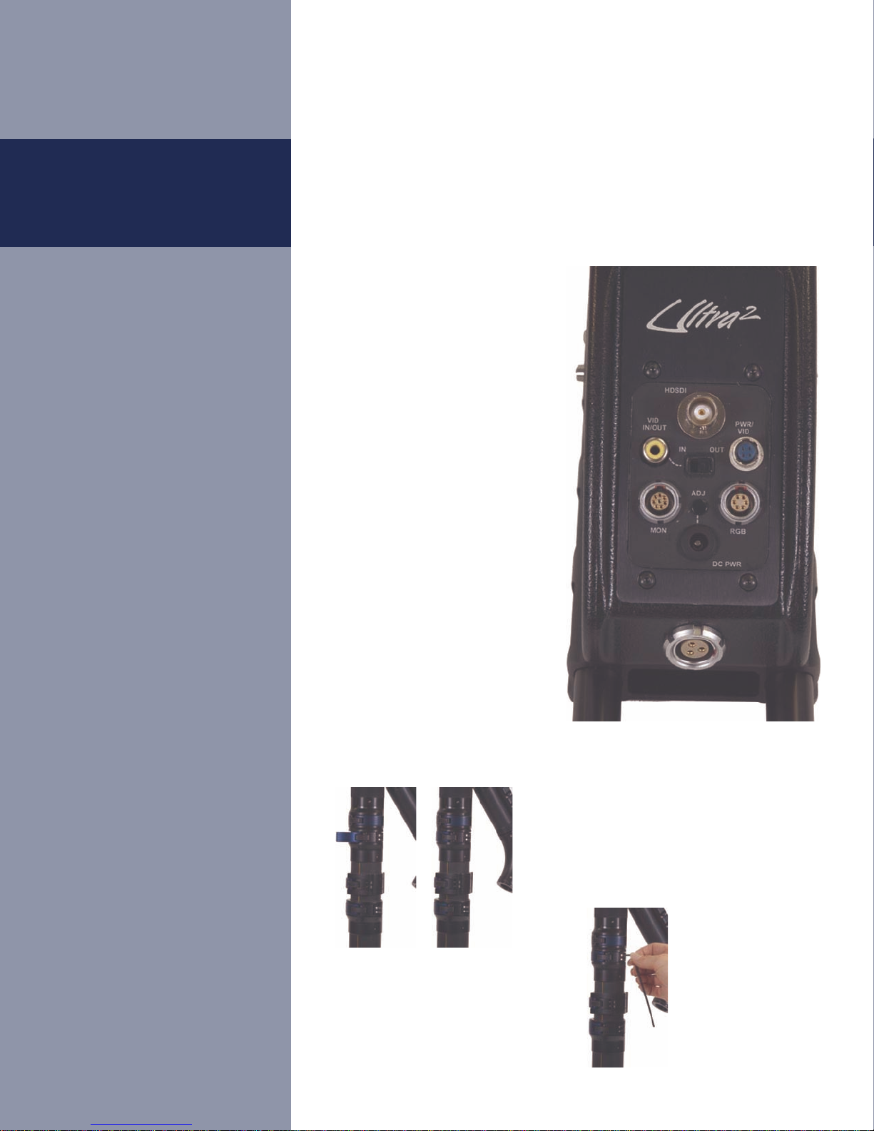
To avoid interference with other systems,
1 of 8 channels can be selected via the
rotary switch on starboard side of nose
box. The remote and the receiver must
be on the same channel. Simultaneously
holding down the top 2 go-to buttons
for 6 seconds will enter the remote into
a channel change mode. The number of
LED blinks will correspond to channel
selected. Change channels by pressing
the fore or aft remote buttons (channel
up or down). After the proper channel
is selected, the programming mode will
time out after 9 seconds and re-flash
the selected channel number. Channel 0
corresponds to 8 flashes.
(For operation outside of the USA) To
select between US and UK frequency
operation, there are two jumpers that
must be changed. One jumper is inside
the nosebox, the other is inside the
remote. They must match for the system
to work. The jumpers are set at the
factory at the time of shipping. (902
– 928MHz US and 868 to 870MHz UK)
The green “PWR” LED on nose box
comes on when the CPU is operational.
If you want, you can remove the pins and
just Velcro the remote to the handle. A
“half moon” filler plate is supplied with
gimbal so that if the remote is removed,
the filler can take its place.
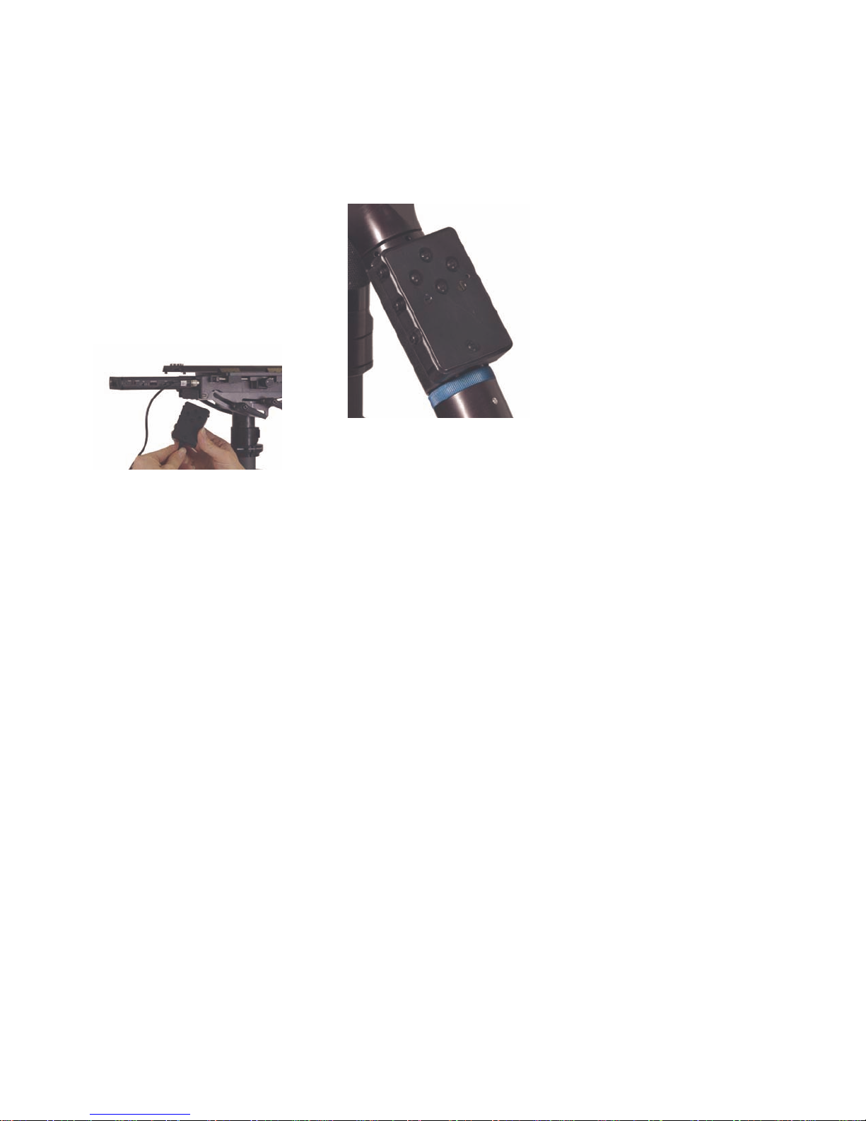
CHECK!! The remote’s green LED
blinks continuously when the battery
gets low. To charge the remote, remove it
from the gimbal handle. Plug the supplied
cable into the remote and the other end
into any one of the three 4-pin HRS
connectors on the sled.

8
FLG,
Voltmeter Box &
Artificial Horizon
FLG/Voltmeter Box
The box is easily removed for servicing,
upgrading, etc.
The frameline generator
(FLG) and adjustments:
Superimposing the display on a
composite (PAL/NTSC) image.
Adjusting the framelines, position,
brightness, and contrast (type??
Volt/amp meter (at rear of base
electronics)
When either a 12V or 24V low battery
condition is detected the small battery
symbol on the backlight voltmeter will
flash.
The voltmeter has 4 different viewing
modes selected by the pushbutton on the
port side. The modes change depending
on whether the battery on switch is set to
12 or 24 volts.
For 24V operation:
Mode 1 or “V1” (top LED) will display
24V battery voltage
Mode 2 or “A1” will show the current
being drawn from the 24V supply.
Mode 3 or “V2” will show the voltage
from the DC-DC converter. (Typically
14.4 to 14.6VDC)
Mode 4 will show what ever is selected
on the voltage select switch.
Alternately, Mode 1 can display the
low voltage threshold. The low voltage
threshold display is selected by switching
to the “24T” position. Adjust the voltage
via the “24T” pot on the rear of the box.
At the factory, this value is set to 29.6
volts, giving you a lot of warning time
under most circumstances. If your loads
are low, you may want to set the voltage
warning lower, but we recommend that
you don’t set it lower than 26 volts. For
“12 volt” operation, the factory sets the
low battery warning at 13.8 volts.
For 12V operation:
Mode 1 or “V1” (top LED) will display
12V battery voltage.
Mode 2 or “A1” will show the current
being drawn from the 12V supply.
Mode 3 or “V2” will show the voltage
from the front panel accessory voltage
supply.
Mode 4 will show what ever is selected
on the voltage switch select switch.
Voltage Select Switch (Mode 4):
“ACC. V” = Voltage from front panel
accessory connector.
“12T” = low voltage threshold for 12V
operation. Set via “12T” pot on rear of
box.
“12V” = Voltage from DC-DC converter
in 24V mode or directly from battery in
12V mode.
“12A” = Current from DC-DC converter
in 24V mode or directly from battery in
12V mode.
The default mode is “12A.”

9
The Artificial Horizon
adjustments, and displays
The Ultra2 artificial horizon has three
controls – a button and two rotary
switches. The button on the top of the
electronics base controls the zero offset,
direction, type of display, and horizon
on/off. The switches are accessible via
holes on the port side of the base. One
switch controls the “range” of the display
and the other the “rate.”
The button on top
Pushing the button
for less than 1
second will reset
the sled level (sets
the “zero offset”).
Place a small
bubble level on a
surface parallel
to the bottom
frame of your
camera (usually
the dovetail plate works well). Angle and
hold the sled until this bubble reads level,
then push and release the horizon button
quickly. The display should now read
“level.”
Pressing the button for more than one
second but less than three will flip the
display direction – useful for going to
low mode and back. The center two
LED’s on display will flash to confirm
that a mode change has occurred. Be sure
to re-set the zero offset when going to
low mode and back.
Pressing the button for three to five
seconds will switch LED display from
bar graph mode to “night rider” dot
mode. Again, the center two LED’s on
the display will flash to indicate that a
mode change has occurred.
Pressing the button for five to thirty
seconds turns Horizon system off or on.
All LED’s will be off.
Pressing button for more than 30 seconds
resets everything to default values.
The range switch sets the sensitivity of
the display. The smaller the range, the
more sensitive the display will be. The
default setting is “0” or +/– 5 degrees.
We suggest you experiment with settings
1 through 6. The range choices beyond 5
degrees might be useful if one wanted to
hold a specific Dutch angle. Setting “F
(15)” is the full range of the sensor.
Rate Choices
Low Pass filter settings (6-Pole
IIR filter)
Setting Hz
0 (default) 5
1 0.75
2 1
3 2
4 3
5 4
6 5
7 6
8 7
9 8
A (10) 10
B (11) 12
C (12) 13
D (13) 16
E (14) 18
F (15) 40
Setting +/- Degrees
0 (default) 5
1 2
2 2.5
3 3
4 3.5
5 4
6 4.5
7 5
8 5.5
9 6
A (10) 6.5
B (11) 7
C (12) 8
D (13) 9
E (14) 10
F (15) 180
The rate switch sets the integration
(or averaging) time. The longer the
integration time is, the slower the
response of the system. A longer
integration time avoids the big, erroneous
signals as you accelerate or decelerate.
The faster the integration time, the
more the indicator will jump around.
Experiment and pick the “rate” you like.
There are sixteen positions, from zero
to nine, and A through F. The default
setting is “0” which equals 5Hz, a good
compromise. Position one (.75Hz) has the
most integration and slowest response.
Position F has the least integration and
fastest response. See the chart below:
The range switch interacts with the rate
switch. Typically, the smaller the range,
the less integration you will need. Ranges
or rates significantly larger than the
default values are not typically used.
Range Choices

10
PowerCube batteries and
rotating mount
The PowerCube batteries are 5.7 Ah
min, 14.8V. Please read the literature that
comes with each battery and charger for
details.
The LEDs on the battery mount will
blink when the low battery threshold
is reached. This feature will only work
when FLG/Voltmeter box is installed (see
below). The circuit breakers in battery
mount are the standard automotive type.
The battery mount pivots approximately
180º to facilitate static and dynamic
balancing, and for inertial control.
Pivoting the battery all the way down
will enable it to get closer to the sled,
reducing pan inertia and/or help with
balancing heavy cameras. Pan inertia is
maximized with the batteries horizontal.
Generally we use the battery in pairs,
generating (nominally) 29.6VDC. It’s
best to use batteries that are roughly
equally charged. Both batteries power
the 14.4 volt DC to DC converter nestled
between the batteries.
Batteries
The on-off switch has two positions, 12
and 24 volts. In the 12 V position, only
the rear battery is connected and the
DC-DC converter is disconnected. For
a lightweight, 14 volt running rig, you
might want to remove the forward battery,
and/or use one Endura 7 battery. (Use
two 7’s for a lightweight 24 volt rig).
Nestled inside the dovetail base,
there’s a sliding accessory plate,
secured with thumbscrews. You can
slide this plate fore or aft to mount a
small recorder, transmitter, etc.

11
As your Lithium-Ion PowerCube™
batteries are used, the voltage drops
at a fairly regular rate. However, the
sample 30 watt discharge chart shows
some interesting information. Hot off the
charger, a single battery will read 16.8
volts, but within a minute drops to 16.1
volt when under load. This is normal, and
not a cause for concern or an indication
of a weak battery.
At the 30 watt discharge rate, the battery
voltage drops slowly for about 3 hours
from 16.1 volts to the “knee” voltage of
13.8 volts – slightly faster at the upper
end, and more slowly as the battery is
discharged. When the voltage reaches
13.8 volts, the voltage drops off very
quickly to 11 volts (within 5 minutes).
The batteries have a self-limiting cut-off
of 11 volts.
Based on this discharge curve, we
suggest you set the Ultra’s battery
warning at 13.8 volts if your total load is
about 30 watts and 5 minutes is enough
warning time.
If you are working with 24 volt film
cameras, where the load changes when
the camera runs, you might set the
battery warning higher, to 28.2 or more
volts for the two batteries in series,
again depending on the load, how much
warning you need, etc. If the voltage
drops below 26 volts when the camera
is not running, you will not get any
appreciable run time with most 35mm, 24
volt film cameras. See page 8 to see how
to set the battery warning.
When running electrically noisy, or high
current draw cameras or accessories, low
voltage indicators may briefly appear.
Voltage sag due to the large loads or
excessive noise spikes on the power lines
may surpass the threshold settings.
Charging your batteries
There is no memory effect with Lithium-
Ion batteries, so there is no need to deep
discharge your batteries to improve
their response. Charging a completely
discharged battery (11 volts) to fully
charged (at 16.8 volts) with a 3.0 amp
charge takes about 2 hours and 40
minutes, but the battery reaches 80% of
a full charge (at about 16.5 volts) in just
over 90 minutes. The last 20% of the
charge cycle takes over an hour.
We suggest that if you have the time,
fully charge your batteries. If you are in a
hurry, however, charge them only for an
hour and a half or less, as an 80% charge
of these batteries is still a lot of watt-
hours, and typically you are using two of
them. Also don’t discharge them much
below 13.8 volts if possible.
If you have two of the VL-4S chargers,
split the batteries equally between the
chargers. Although all batteries are
charged simultaneously, with one, two, or
three batteries on the charger, the charge
current is 3.0 amps per battery. When the
fourth battery is added to the charger, the
charge current for each battery drops to
2.3 amps, which will increase the time it
takes to charge each battery.
Other manuals for Ultra2
2
Table of contents
Other Steadicam Camera Accessories manuals

Steadicam
Steadicam ARCHER2 User manual

Steadicam
Steadicam G-70x User manual

Steadicam
Steadicam Ultra2 User manual

Steadicam
Steadicam Merlin 2 Manual instruction

Steadicam
Steadicam Volt User manual

Steadicam
Steadicam Ultra2 User manual

Steadicam
Steadicam MERLIN2 User manual

Steadicam
Steadicam G-70x Arm User manual

Steadicam
Steadicam Merlin Arm & Vest Technical manual

Steadicam
Steadicam Merlin Manual instruction