Steadicam M-1 User manual


A word from Garrett Brown 1-1
M-1 System Components 1-2
The Stage
Stage Components 2-1
Camera Installation 2-2
Camera Removal 2-3
Drive Mechanisms 2-4
The Post
Post Components 3-1
180° Post Reversal 3-2
The Gimbal
Gimbal Components 4-1
The Monitor Mount
Monitor Mount Components 5-1
Monitor Positioning 5-2
The Base and Battery Mount
Base and Battery Mount Components 6-1
Battery Positioning 6-2
Power Management and Electronics
Special Notes 7-1
Connector Pin Diagrams 7-2
Adjustments and Maintenance
Separating the Modular Components 8-1
Clamp Adjustments 8-2
Drive Knob Adjustments 8-3
Gimbal Disassembly and Cleaning 8-4
Gimbal Assembly 8-5
Lubrication and Exterior Cleaning 8-6
Accessories for the M-1 System 9-1
Contact Tiffen 9-2
Table of Contents
M-1 Operator’s Manual
Rev. A
p/n LIT-815000
STEADICAM®and Exovest®are trademarks of The Tiffen Company. Other trademarks are the property of their respective owners.
All specifications stated within this manual are subject to change without notice.
© 2015 The Tiffen Company. Written by E. Barthelman.


Congratulations on your new M-1!
Dear Friends,
There have been three generations of Steadicam® operators since we began it all in 1976.
Thousands of us have graced tens of thousands of movies and shows with the unique visual
music of Steadicam—played worldwide on seven generations of Steadicam equipment.
Many of our innovations—think extendable monitor and battery, no-tools clamps and
integral super post—became industry must-haves, but our exclusive tilt-head and motorized
stage remain essential to the very highest standard of Steadicam precision.
And now my inventing colleagues at Tiffen have raised the bar once again and I'm proud to
report that nearly all aspects of modern operating—mechanical, electronic, artistic,
ergonomic and political—are augmented and advanced.
M-1 is for Modular—user-configurable, upgradable, swappable—with a host of superbly
engineered new features:
Ultra-rigid post, stage and base
Vernier-drive tilt-head
Super-precise removable gimbal
Indexed center post with custom hi-amp bayonet connectors
Quick-release camera plate system with patented safety latch
Monitor mounts instantly to any post
Super-adjustable monitor and battery pivots
3x true HD video lines and 10 hi-amp power ports
Industry-best level-keeping, hi-def and voltage options
In short, the M-1 is brilliant—rigid, precise, tool-free, super-adjustable and fast.
Above all, it is infinitely configurable and as close to future-proof as a rig can be.
Good luck with your new Steadicam M-1 and good shooting!
I think it's the best Steadicam ever... Where was this baby when I needed it?
Garrett Brown, Philadelphia 2015
www.garrettbrown.com
A word from Garrett Brown
1-1

The M-1 System Components
The Post
Modular ends make system maintenance and upgrades quick and painless
Carbon fiber posts are indexed to ensure exact alignment
The Stage
Quick release dovetail
Tilt-able to maintain dynamic balance
Camera power and video connections
The Gimbal
Removable handle for future upgrades
The Monitor Mount
Allows monitor to be mounted to either post and inverted
Monitor tilts at the center of gravity for angle adjustment
Modular rods extend for optimal viewing
The Base and Battery Mounts
Monitor power, accessory power and video connections
Battery mount rotates 180˚ to suit user preference
Modular rods extend to increase panning inertia
1-2

The Stage
Dovetail Plate
Maximum rigidity and mounting options
Index marks on side for repeatability
Clamp Lever
Safety latch design with drop-in loading
Adjustable tension without shims
Fore/Aft Drive Knob
Fine balance adjustment
Side/Side Drive Knob
Fine balance adjustment
Nose Box
Power and tally ports
Accessory Rod Mounts
For Tiffen accessories and custom applications
15mm by 60mm spacing
Tilt Stage
Dual cam levers to ensure rigidity
Downward tilt from 0°-15°
2-1

Components
Fore/Aft Drive Knob
Fine balance adjustment
adjustment
Side/Side Drive Knob
Fine balance adjustment
Rear Electronics
High-definition video connectors
Power ports
Backlit Bubble Level
High precision, spirit level
Tilt Drive Knob
Easily tilts the camera while the
rig is docked or while worn
Stage Connector
Modular mechanical and electronics junction
Indexed to ensure exact alignment with post
Safety Stops
Prevents unintended
camera removal
S
F
onnector
The Stage
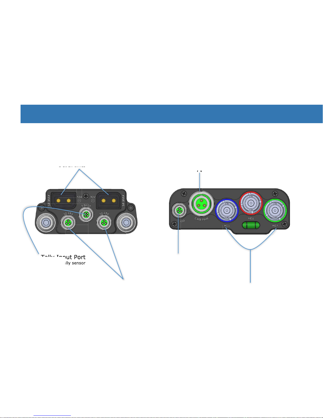
Nose Box Electronics
Rear Electronics
Dual P-Tap Ports
12 Volts supplied at all times
12 Volts supplied at all times
12 Volts supplied at all times
12 Volts supplied at all times
Tally Input Port
Use with available tally sensor
Dual 12/24 Volt LEMO 0B Ports
12 Volts supplied at all times
12 and 24 Volts simultaneously when in 24V mode
Tally Input Port
Use with available tally sensor
Camera Power Port, LEMO
®
2B
12 Volts supplied at all times
12 and 24 Volts simultaneously when in 24V mode
Tally Input Port
Tally Input Port
12 and 24 Volts simultaneously when in 24V mode
ISO Port, LEMO 0B
Provides an isolated port for
dedicated accessories
High-Definition Video Ports
Three direct, 3G compatible connections to the M-1 base
Color-coded at each end
2-1
Components
The Stage
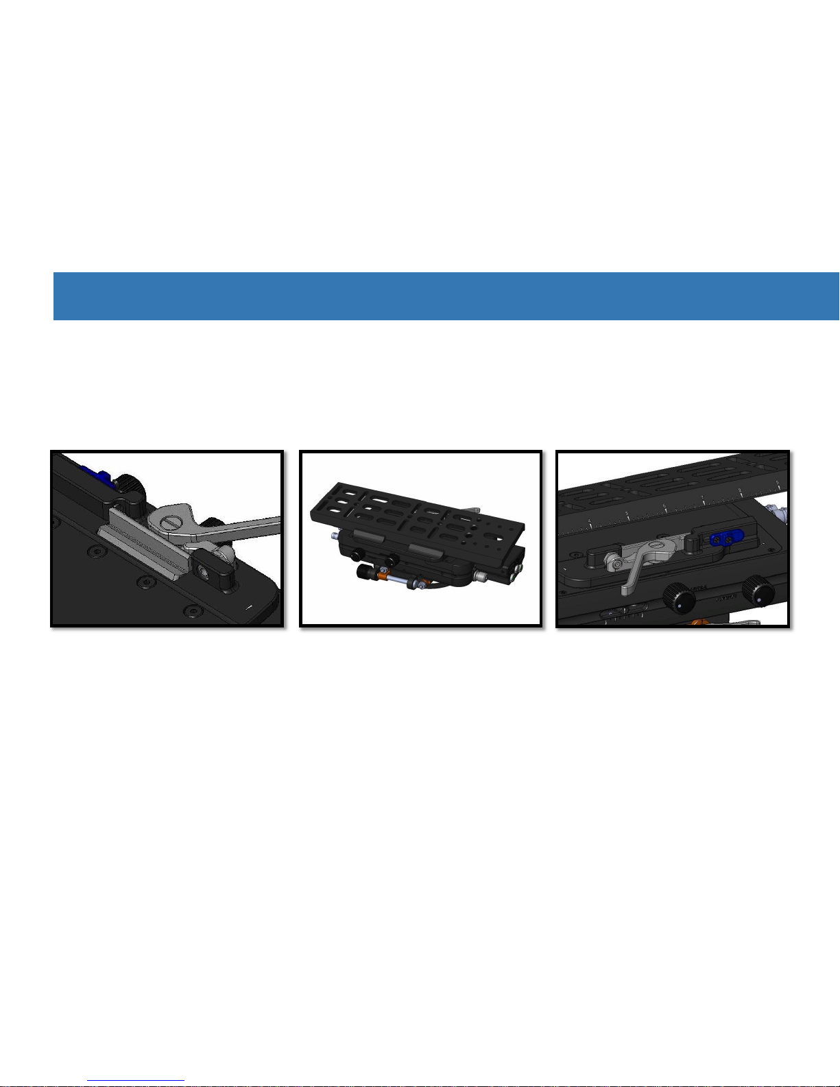
Camera Installation:
The dovetail lock system was designed to ensure reliable camera safety. Mounting the camera to the M-1 encourages you
to keep at least one hand on the camera at all times until it is securely fastened. With your camera mounted to the
dovetail plate, follow these steps:
The stage is ready for the camera
plate. Note that the dovetail lock
and clamp lever are both open.
Place the dovetail plate against
the passive side of the clamp.
With two hands still on the
camera, tilt the plate into the
dovetail lock.
2-2

The weight of the camera will
press the dovetail lock down
and release the safety latch.
You’ll hear a satisfying click.
The camera and plate can be
moved fore and aft for coarse
balancing, but the safety stops
prevent any unintended
release of the camera.
Close the clamp lever to firmly
secure the camera onto the M-1.
Note:
If the dovetail lock has been pressed down while the dovetail plate was out, you will have to slide the safety latch to the
right to reopen the lock. This can be a fun test for your new camera assistant.
Camera Installation

The Stage
With your left hand, secure the
camera throughout this process.
The camera is still retained by
the safety latch.
Open the clamp lever.
Camera Removal:
As with installing the camera, separating the camera from the M-1 is designed to encourage users to keep at least one
hand on the camera at all times. Unlocking the clamp and removing the camera is a quick and easy process that will
become second nature in no time.
2-3

Push and hold the safety
latch to the right.
Keeping the safety latch held to
the side, tilt the dovetail plate
out of the dovetail lock.
Lift the camera off the rig.
Caution:
Do not remove safety screws from the dovetail plate or it could slide out if you forget to lock the clamp lever.
Camera Removal
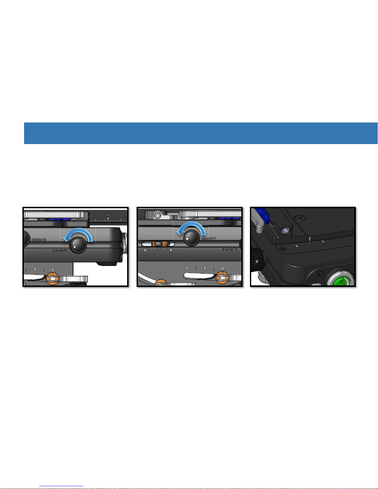
Fore/aft adjustment knob: turning
towards the front of the rig will
move the camera weight forward.
Each drive has a scale indicating
the location and range. Starting
with the scales centered leaves
the most room for adjustment.
The Stage
Side-to-side adjustment knob:
turning towards the front of
the rig will move the camera
weight to the left.
Balance Drives:
Each knob has a twin on either side of the stage so you can adjust the balance from either side of the rig.
With the coarse balancing done and the camera locked in place, fine balancing can be finished with the drives:
Note:
Think about the drive knobs as turning towards the front or rear of the stage. The knobs turn clockwise on one side and
counterclockwise on the other side for the same stage movement.
2-4
Unlock cam levers.
Always re-lock cam levers.
Turn tilt drive to achieve desired
camera angle. Counterclockwise
turning tilts the camera down.
Tilt Drive:
The tilt drive enables you to easily tilt the camera relative to the post, which allows you to maintain dynamic balance
while panning and helps control headroom. It’s also very useful in low mode. The tilt stage offers 15˚ of downward tilt,
but if you need to tilt the lens upward, read about the 180˚ post reversal in the next section.
Drive Mechanisms
Tip:
The scale on the cam lever side of the tilt stage is handy for repeating setups. For example, if you have a tilt you prefer
the scale allows you to dial it in quickly without any guesswork, saving time.

Notes:

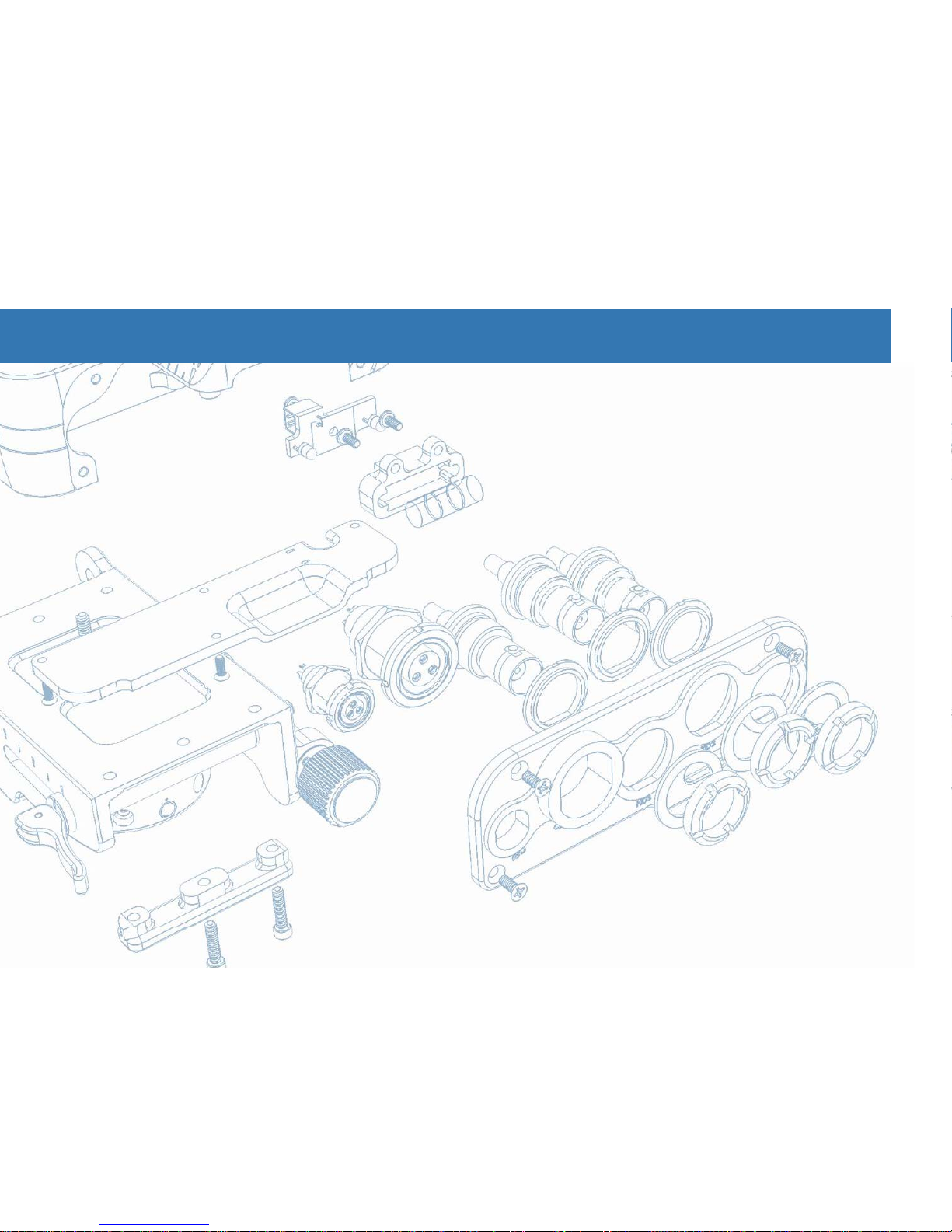
Stage Connector
Electrical and mechanical junction to stage
Gimbal Post
Safety Line
Inside posts
Prevents hyperextension
Allows 180˚ reversal
The Post
The M-1 Post
The new modular post for the M-1 system offers maximum rigidity whether it’s built short or at full
extension. It also allows users quick access to the stage, gimbal and base components for future upgrades,
mods and maintenance. The stage and base are both indexed to the post and the post segments are
indexed within each other, making alignment of the various components practically automatic.
Gimbal Post
3-1

Components
Base Connector
Electrical and mechanical junction to the base
Lower Post
Index Groove
Ensures alignment of posts
Lower Post
Clamp Lever
Over-center, tools-free lock
Shown here closed
Reference Lines
Etched into rear of both posts
Confirms perfect alignment
Lower Post

The Post
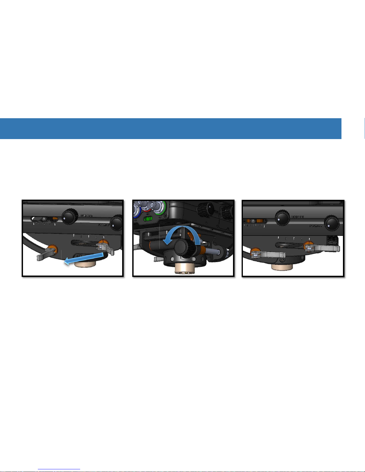
180˚ Post Reversal
In some situations you may benefit from having the stage turned to face the other direction; for example, with large camera
setups (like 3D) that need additional room directly in front of the stage, or to enable the tilt-head to tilt the lens upward.
Without a camera or batteries on
board, unlock the clamp lever and
extend the lower post.
Slide the lower post until the
yellow reference line changes to
red. Continue until you feel the
post index disengage, allowing
both sections to rotate.
Carefully rotate the lower post
180˚ until the indexing system
allows the posts to rejoin. Insert
the lower post back into the
gimbal post.
Caution:
To prevent damage to the cables inside the post, be careful not to twist the safety line past 360˚ by taking note of
the direction you turn the post in this process. For example, we suggest turning the lower post to the right for the
reversal and then returning it back to the left.
3-2
Table of contents
Other Steadicam Camera Accessories manuals

Steadicam
Steadicam Volt User manual

Steadicam
Steadicam ARCHER2 User manual

Steadicam
Steadicam Ultra2 User manual

Steadicam
Steadicam Merlin Arm & Vest Technical manual

Steadicam
Steadicam Ultra2 User manual

Steadicam
Steadicam MERLIN2 User manual

Steadicam
Steadicam Merlin 2 Manual instruction

Steadicam
Steadicam G-70x Arm User manual

Steadicam
Steadicam X3 User manual

Steadicam
Steadicam Merlin Manual instruction


