Stealth Products Pediatric i-Drive Control Harness User manual

Alternative
Drive Controls
i-Drive Control Harness
Owner’s Manual - Maintenance Guide
i-Drive Control Harness

1
Table of Contents
Customer Satisfaction ...................................................................... i
Important Information............................................................... ii-iii
Warranty .......................................................................................................ii
Supplier Reference....................................................................................ii
Warning Labels..........................................................................................iii
Limited Liability.........................................................................................iii
Testing ..........................................................................................................iii
Design & Function ....................................................................... 1-6
Intended Use.............................................................................................. 1
Features........................................................................................................ 1
Mounting..................................................................................................... 1
IDCH Package ............................................................................................ 2
IDCH Accessories ..................................................................................... 3
IDCH Replacement Parts ....................................................................... 4
Conguration............................................................................................. 5
Additional Link ......................................................................................5-6
Installation Instructions ............................................................ 7-14
Mounting a Joystick to the Control Harness.............................7-8
Removal/Addition of a Link ................................................................. 9
Adjustment ........................................................................................ 10-12
Tools ............................................................................................................13
Installation Plan ......................................................................................13
Joystick Installation ........................................................................ 13-14
First-Time Use................................................................................. 15
Dealer Assistance ...................................................................................15
User Testing..............................................................................................15
Conditions of Use ..................................................................................15
Maintenance ................................................................................... 16
Care and Maintenance.........................................................................16
Cleaning.....................................................................................................16

i
Customer Satisfaction
Stealth Products is committed to 100% customer satisfaction. Your complete
satisfaction is important to us. Please contact us with feedback or suggestions to help
us improve the quality and usability of our products.
You may reach us at:
General
Read and understand all instructions prior to the use of the product. Failure to adhere
to instructions and warnings in this document may result in property damage, injury,
or death. Product misuse or failure to follow instructions will void the warranty.
Immediately discontinue use if any function is compromised, if parts are missing or
loose, or if any component shows signs of excessive wear. Consult with your supplier
for repair, adjustment, or replacement.
All persons responsible for tting, adjustment, and daily use of the devices discussed
in these instructions must be familiar with and understand all safety aspects of the
devices mentioned. In order for our products to be used successfully, you must read
and understand all instructions and warnings, and maintain our products according to
our instructions on care and maintenance.
The installation instructions will guide you through this product’s options and
possibilities.
Instructions are written with the expressed intent of use with standard congurations.
They also contain important safety and maintenance information, as well as describe
possible problems that can arise during use. For further assistance, or more advanced
applications, please contact your supplier or Stealth Products at (512) 715-9995 or toll
free at (800) 965-9229.
Always keep the operating instructions in a safe place so they may be referenced as
necessary.
All information, pictures, illustrations, and specications are based on the product
information that was available at the time of printing. Pictures and illustrations shown
in these instructions are representative examples and are not intended to be exact
depictions of the various parts of the product.
Stealth Products, LLC
104 John Kelly Drive, Burnet, TX 78611
Phone: (512) 715-9995 Toll Free: (800) 965-9229
Fax: (512) 715-9954 Toll Free: (800) 806-1225
info@stealthproducts.com
www.stealthproducts.com
UK Authorized Representative
MDSS GmbH
Schigraben 41
30175 Hannover
Germany
SODIMED SA
Chemin Praz Devant 12
1032 Romanel sur-Lausanne
Switzerland
MDSS-UK RP
6 Wilmslow Road, Rusholme
Manchester M14 5TP
United Kingdom

ii
Important Information
Supplier Reference
Supplier:
Telephone:
Address:
Purchase Date:
Model:
Warranty
Our products are designed, manufactured, and produced to the highest of
standards. If any defect in material or workmanship is found, Stealth Products will
repair or replace the product at our discretion. Any implied warranty, including the
implied warranties of merchantability and tness for a particular purpose, shall not
extend beyond the duration of this warranty. Stealth Products does not warrant
damage due to, but not limited to: misuse, abuse, or misapplication of product,
and/or modication of product without written approval from Stealth Products, LLC.
Any alteration or lack of serial number, where applicable, will automatically void all
warranty.
Stealth Products, LLC is liable for replacement parts only. Stealth Products, LLC
is not liable for any incurred labor costs.
Stealth Products warrants against failure due to defective materials or
workmanship:
Covers: 2 years
Hardware: 5 years
Electronics: 3 years
In the event of a product failure covered by our warranty, please follow the
procedures outlined below:
Call Stealth Products at (512) 715-9995 or toll free at (800) 965-9229.
Request a Return Authorization (RA) form from the Returns Department and follow
the documentation instructions. Additional warranty information may be found by
visiting the website at https://stlpro.site/returns-n-warranty, or by scanning the
Warranty Information QR code on the back of this manual.
Copies of this manual may be downloaded by accessing the Stealth website (https:/
/stlpro.site/stealth-docs) and searching “P132D399” in the search bar, or by
scanning the Online User Manual QR code on the back of this manual.
CAUTION
These products are designed to be tted, applied, and
installed exclusively by a healthcare professional trained for
these purposes. The tting, application, and installation by a
non-qualied individual could result in serious injury.

iii
Important Information
Warning Labels
Warnings are included for the safety of the user, client, operator, and property.
Please read and understand what the signal words DANGER,WARNING,
CAUTION,NOTICE, and SAFETY mean, and how they could aect the user, those
around the user, and property.
Limited Liability
Stealth Products, LLC accepts no liability for personal injury or damage to
property that may arise from the failure of the user or other persons to follow the
recommendations, warnings, and instructions in this manual.
Stealth Products does not hold responsibility for nal integration of nal
assembly of product to end user. Stealth Products is not liable for user death or
injury.
Testing
Initial setup and driving should be done in an open area free of obstacles until the
user is fully capable of driving safely.
CAUTION Identies a potential situation which, if not avoided, may
result in minor to moderate injury and property damage.
WARNING Identies a potential situation which, if not avoided, may
result in severe injury,death, and property damage.
DANGER Identies an imminent situation which, if not avoided, may
result in severe injury,death, and property damage.
NOTICE Identies important information not related to injury,
but possible property damage.
SAFETY
Indicates steps or instructions for safe practices,
reminders of safe procedures, or important safety
equipment that may be necessary.

1
Design & Function
Intended Use
The i-Drive Control Harness is a secure platform to attach control devices in
positions that accommodate users limited in their ability to use traditional joysticks
or switch combinations. Smaller switches and joysticks with various input force
requirements can be congured to assist users with conditions ranging from
paralysis to paraplegia, allowing them the freedom to control devices and mobility
platforms with nearly any facial surface.
Features
The i-Drive Control Harness:
▪ Is lightweight and discreet;
▪ Is compatible with the mo-Vis Micro and Multi joysticks, as well as
Stealth's IDPMP joysticks;
▪ Is height-, depth-, and angle-adjustable through the use of tracks, swivel
mounts, and links;
▪ Can be tted easily with Twister switches and ber optics using Loc-Line
as an additional accessory; and,
▪ Is supplied with a Stealth Positioning body securement belt, which helps
to ensure the IDCH remains secure and stable.
Mounting
The i-Drive Control Harness is designed for joysticks to be easily interchangeable
and has additional access points for the use of switches and/or ber optics, if
required.
▪ mo-Vis Multi and Stealth's IDPMP joysticks require the same mounting
hardware.
▪ mo-Vis Micro joystick is mounted by removing the joystick mount used
by the Multi and IDPMP joysticks and adding Stealth's joystick strap.
▪ Track versatility and Loc-Line switch options equate to nearly unlimited
positioning possibilities for the user.

2
Parts and Accessories
IDCH Package
The i-Drive Control Harness part numbers/descriptions are as follows:
Product Description Part
Number Image
Pediatric i-Drive Control Harness
Small i-Drive Control Harness
Medium i-Drive Control Harness
Large i-Drive Control Harness
IDCH-P
IDCH-S
IDCH-M
IDCH-L
i-Drive Control Harness
Standard Belt
IDCH-SB*
(standard for Pediatric, Small and Medium IDCH sizes)
* All belts are universal
i-Drive Control Harness
Extra Large Belt
IDCH-XLB*
(standard for Large IDCH sizes)

3
Parts and Accessories
IDCH Accessories
The IDCH accessories include switches and ber optics installed on Loc-Line. The
part numbers/descriptions are as follows.
Product Description Part Number Image
Left Side Single Twister Basic
Button on Loc-Line - Specify Color
*See colors below
IDCH-A1L
Right Side Single Twister Basic
Button on Loc-Line - Specify Color
*See colors below
IDCH-A2R
Left Side Fiber-Optic on Loc-Line
(Requires IC24F-1) IDCH-AFL
Right Side Fiber-Optic on Loc-Line
(Requires IC24F-1) IDCH-AFR
IDM-24 Twister Basic Button - Yellow
IDM-25 Twister Basic Button - Black
IDM-26 Twister Basic Button - Red
IDM-27 Twister Basic Button - Blue
IDM-28 Twister Basic Button - Green

4
Parts and Accessories
IDCH Replacement Parts
Additional/Replacement parts may be ordered if necessary. The part numbers
descriptions are as follows:
Product Description Part Number Image
Additional Link for Harness IDCH-A1L
Replacement Cover for
Control Harness
IDCH-PC
IDCH-SC
IDCH-MC
IDCH-LC
6" Loc-Line for Mounting
Accessories to the
Control Harness
IDCH-FL6
Pediatric i-Drive Control Harness Collar
Small i-Drive Control Harness Collar
Medium i-Drive Control Harness Collar
Large i-Drive Control Harness Collar
IDCH-PNC
IDCH-SNC
IDCH-MNC
IDCH-LNC
Mount for
IDM-MULTI-9 & IDPMP-1,9 IDCH-JM01
Mount for IDM-MICRO-9 IDCH-JM02

5
Parts and Accessories
Conguration
i-Drive Control Harness Belt (provided with IDCH order):
• Two sizes are available.
• Standard belt size - 16" x 3 3/4"* (Pediatric, Small and Medium IDCH)
• Extra Large Belt size - 18 1/2" x 4"* (Large IDCH)
• The belt is attached at the front of the collar, via buckles, and provides support along
the client's back. The belt helps to prevent the harness from shifting out of position.
• The belt is easily adjustable, side-release, dynamic material.
Size Chest Circumference
Minimum*
Chest Circumference
Maximum*
Pediatric 27" 42"
Small 30" 45"
Medium 33" 48"
Large 36" 66"
CAUTION Do not overtighten belt straps.
NOTICE Measurements shown include pad sizes only.
NOTICE Webbing may be trimmed to size if necessary.
* Measurements are approximate.
Additional Link
An additional link is available for IDCH (IDCH-LINK):
• If additional height is required for proper positioning, the IDCH-LINK may be ordered
and easily attached.
• An additional link will provide 1-3/4" of additional height.

6
Parts and Accessories
Loc-Line with Twister Basic Button/Fiber Optic Switch
• Switches, attached by Loc-Line tubing, may be ordered for the IDCH.
• Approximately 12" of Loc-Line is provided.
• Loc-Line will be secured via M5 x .8 x 25mm SHS & M5 locknuts and share the same
track as the swivel mount.
• Fiber optic switches require the IC24F-1.
• The Loc-Line can be easily adjusted and oriented to the client's needs.
Replacement Neck Cover (IDCH-PC, SC, MC, LC)
• Neoprene fabric (standard).
Loc-Line for Mounting Accessories (IDCH-FL6)
• All switches are mounted on 12" of Loc-Line.
• Additional Loc-Line may be ordered in 5-3/4" increments.
• The depth position of the switches can be adjusted on the track by loosening the nut
under the track. Slide Loc-Line along the track until you have reached the desired
position and tighten.
CAUTION Do not over-tighten the nut, as this can
crack or damage the Loc-Line tubing.
NOTICE
When a switch has been installed on the Loc-Line, the length
cannot be altered. If there is a possibility that more length
for the switch site will be necessary, we advise that additional
Loc-Line (IDCH-FL6) be ordered at the time of purchase.
Tools
• 2mm Hex Key
• 3mm Hex Key
• 4mm Hex Key
• Phillips Head Screwdriver

7
Installation Instructions
WARNING The i-Drive Control Harness should be installed
ONLY by a qualied service technician.
Installation Plan
Set up an installation plan before starting the installation. Based on the user's
needs, this plan should specify:
• Which joystick is necessary for the client to operate.
• What height the links should be adjusted to.
• At what angles the links need to be placed.
Joystick Installation
To install the mo-Vis Micro, Multi, or Stealth IDPMP joysticks, follow the
instructions in the next section. To program these joysticks, please refer to the user
manual that came with the joystick, and carefully follow the instructions:
• Determine the correct height of the links on the collar for the user. If additional
height is necessary, links can be purchased.
• Adjust the links to the proper angles and secure the screws.
CAUTION
Use the proper tools to install and adjust the
i-Drive Control Harness. The use of improper tools
may cause damage to the device.
CAUTION Tighten the screws rmly, but not excessively.
Excessive force may damage the unit.
• The joystick mount on the collar is for mounting the Multi or IDPMP Joystick with the
proper screws. To use the Micro Joystick, remove the joystick mount from the collar.
Use the mounting strap to mount the Micro Joystick to the links on the IDCH.
• Place IDCH on client and make any nal adjustments with the position of the joystick
and the angle at which it is mounted for the client.
• Wrap the belt around the back of the client and secure it to the front of the IDCH.
CAUTION Any connection must always be secured with all delivered
screws. Use only the screws provided in the package.

8
Testing
To mount the mo-Vis Multi joystick:
• Use the four screws provided in the Multi
Accessory Pack to mount the joystick.
• The screws will travel through the joystick mount
on the IDCH and into the base of the Multi Joystick.
• USB ports should be oriented to the client's right
side for standard conguration of the joystick.
Standard Conguration
USB ports pointing to the
user's right side for forward
direction orientation
Joystick is mounted with
four screws through the
joystick mount.
Mounting a Joystick to the Control Harness
Mounting the IDPMP joystick:
• Use the two screws provided in the IDCH kit
to mount the IDPMP joystick.
• Screws will travel through the base of the
mount on the IDCH and into the base of the
IDPMP joystick.
• For standard conguration of the joystick,
orient the dimple to the front, facing away
from the client.
Standard Conguration
Dimple facing the front,
away from the user, for
forward direction
orientation.
Joystick is mounted with
four screws through the
joystick mount.

9
Installation Instructions
Step 1: Place Multi or IDPMP joystick atop the joystick mount. Match the holes on
the base of the joystick to the holes on the mount.
Step 2: Secure joystick to mount by inserting the provided screws through the
matching holes.
Step 3: Secure the power cord to the links via the 1/4" clips.
Step 1: Loosen and remove screws securing the joystick mount to the Nino Link.
Step 2: Remove the joystick mount.
Step 3: Slightly loosen M5 x 0.8 x 6mm BHS and position the strap mount around
the Micro joystick. Tighten the screws with a 3mm Hex Key.
Step 4: Attach the joystick strap mount to the Nino Link with screws and tighten
with a 3mm Hex Key.
WARNING Ensure the joystick power cord is fed through the cutout in
the joystick mount, without kinking or splicing.
When mounting a mo-Vis Micro joystick:
• The Multi/IDPMP mount on the IDCH will be
removed. Replace the mount with the iDrive
Control Harness Micro joystick mount.
• The arrow on the base of the joystick should be
pointing away from the client for standard
conguration of the joystick.
Standard Conguration
Arrow on the base of the
joystick facing away from
the user.
CAUTION Use caution around feeding tubes,
wounds, or other sensitive areas.

10
Installation Instructions
Removal/Addition of Link
If additional height is required:
Step 1: Locate the link screw on the top link. Remove the M5 x 0.8 x 20mm FHS
from the link detaching the joystick mount and link nut.
Step 2: Line up the holes on the new link and add it to the open end. Make sure
to align the link nut position on the same side as the other links.
Step 3: Insert the link screw and tighten it with a 3mm Hex Key.
Step 4: Remove the link screw at the top of the new link.
Step 5: Add the joystick mount and link nut, lining up all the holes. Insert the link
screw and tighten.
CAUTION
DO NOT OVER-TIGHTEN SCREWS.
This could cause wearing of screws or joystick threads,
causing the client to lose ecient control.
Remove the link
and joystick mount.
Remove the
screw and
link nut.
Replace with
additional link.
Loosen
this
screw.
Tighten this
screw into
the link nut.
Remove this screw
and link nut and
replace joystick
mount on this end.
Position the joystick
mount and tighten
this screw to secure
it in place.

11
Adjustment Instructions
NOTICE
Cutting the arms should be performed only if necessary.
Cuts on the arms need to be made one inch
below the desired mounting position.
The IDCH has multiple points of adjustment.
To determine the size needed, measure the circumference of the client's neck.
Refer to the table below for sizing information.
Collar Size Arm Lengths
Part Number Size Width Circumference
IDCH-P Pediatric 3-1/2" 11"
IDCH-S Small 4-1/2" 14-1/8"
IDCH-M Medium 5-1/2" 17-1/4"
IDCH-L Large 6-1/2" 20-1/2"
Size Inches
Pediatric 7"
Small 9"
Medium 10"
Large 11"
Height Adjustment
• The arm lengths are standard to the size of the assembly ordered. The
mount can be moved closer to the client by moving the latches up the arms.
• If the distance to the joystick does not meet the client's needs, the arms may
be shortened by cutting them.
• To adjust the length of the arms:
• Loosen the set screws securing the latch to the arms.
• Slide the arms up or down in the latches to the desired height.
• Tighten the set screws to secure the arms at the desired height.
• If the height is adjusted to the point the arms protrude out the bottom of
the latch, they should be trimmed to avoid contact that may cause
discomfort for or injury to the user.
Adjustment
CAUTION After making cuts to the arms, be sure to
smooth all sharp edges prior to nal assembly.

12
Adjustment Instructions
Lateral Adjustment & Depth Adjustment
• Lateral adjustment of the track and joystick mount is determined by the size of the
collar.
• 3 1/4" of depth adjustment is available for all harnesses.
Size Inches of Lateral
Adjustment
Pediatric 3"
Small 4"
Medium 5"
Large 6"

13
Adjustment Instructions
Swivel Link
Locked
Swivel Link
Unlocked
Angle and Link Adjustment
• The swivel link, located at the base of the joystick mount, oers 360° of adjustment
for the user.
• 90° of adjustment forward and backward provides the client with the ability to move
the joystick as close to them as necessary.
• A quarter-turn in a downward direction will release the locking mechanism and allow
the client to adjust the swivel mount. A quarter-turn in an upward direction locks the
swivel mount.
• The links and joystick mounts can be adjusted to various angles to best t the client's
needs.
To adjust the angle of the joystick mount:
Step 1: Turn the handle of the swivel link
Step 2: With a 3mm Hex Key, loosen the screw at the base of the link beneath the
joystick mount.
Step 3: Rotate the joystick mount to the desired angle.
Step 4: Tighten the screw with the 3mm Hex Key to secure the desired joystick
adjustment.

14
Adjustment Instructions
Removing the Collar
The track may be released from the collar (illustrated from the client's perspective).
Three (3) dierent options are available to remove the arms from the latch:
Left Release
(Swings to client's right side)
Right Release
(Swings to client's left side) Full Release
Step 1: For your safety, unbuckle the belt from the collar.
Step 2: Choose the direction to release the arms from the latch.
Step 3: Place a rm hold on the latch and arm.
Step 4: Pull latch away from client.
Step 5: Secure and turn latch.
Step 6: Remove from around the neck.
WARNING Discontinue use if any product's function becomes
compromised, loose, shows signs of excessive wear, missing
parts, or does not function as intended.

15
First Time Use
Replacing the IDCH Belt
Step 1: With the 2mm hex key,
unscrew and remove the M3 x
0.5 x 12mm at head screws.
Separate the arms (B) from the
latch (C1).
Step 2: Loosen and remove
the M5 x 0.8 x 20mm FHS (2)
from the i-Drive latch (top).
Step 3: Pull straight
upward on the latch to
separate it from the
track.
B
C1
STEP 1
STEP 2
STEP 3
This manual suits for next models
7
Table of contents
Other Stealth Products Personal Care Product manuals
Stealth Products
Stealth Products HMO400-KK User manual

Stealth Products
Stealth Products True Forming Back Flex Guide

Stealth Products
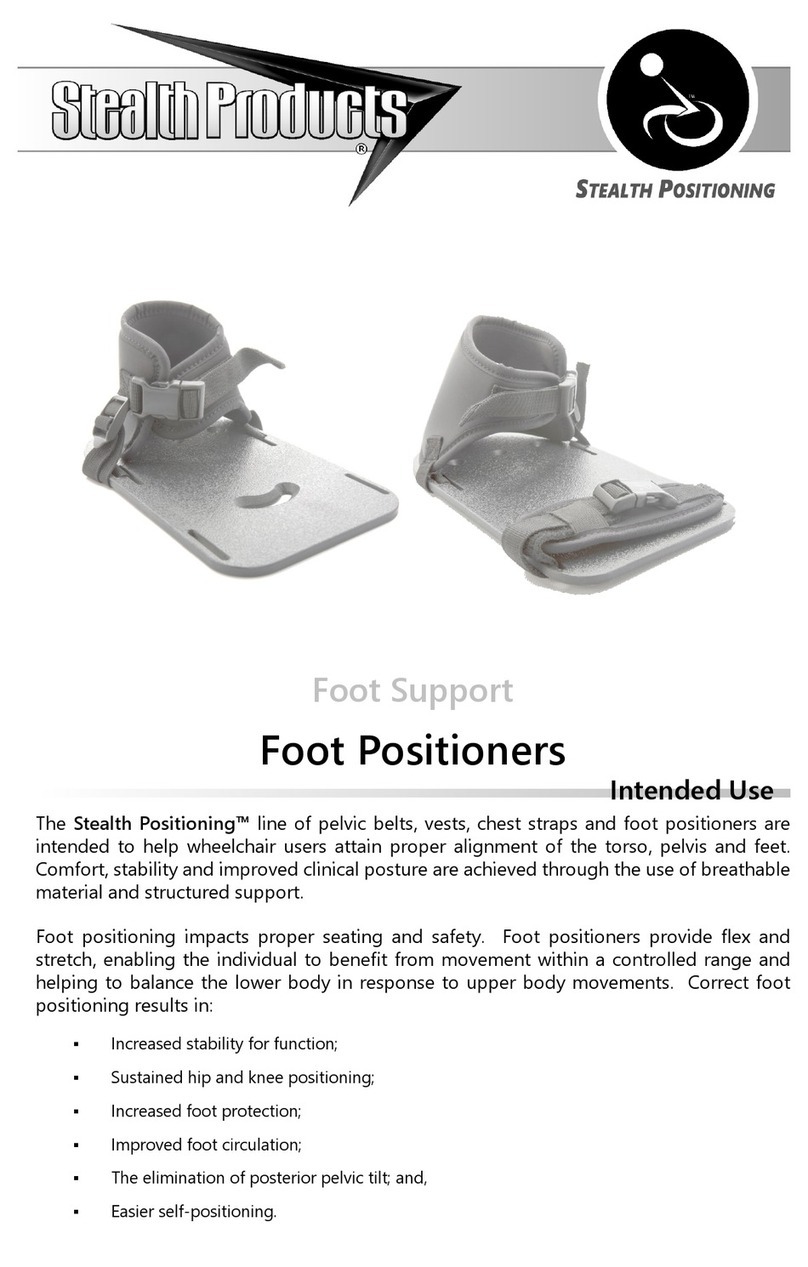
Stealth Products Stealth Positioning Foot Support User manual

Stealth Products
Stealth Products Tarta Guide
Stealth Products
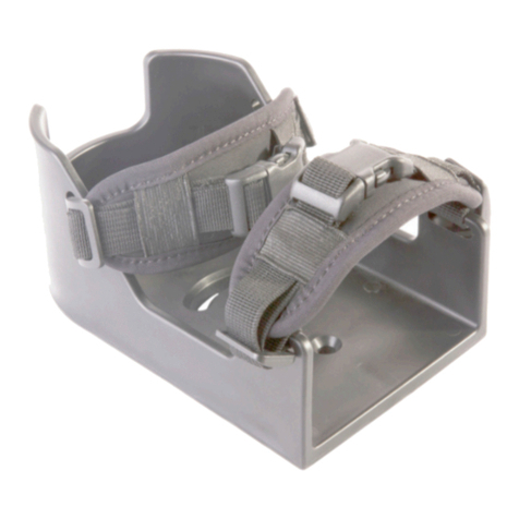
Stealth Products Stealth Positioning Foot Positioners User manual