Stealth mo-Vis Series User manual

USER MANUAL
All-Round/All-Round Lite Joystick
Stealth’s mo-Vis Series Multifunctional Operable
Wheelchair Joysticks
Alternative Drive Controls

i
Customer Satisfaction 1.0
General
The Stealth mo-Vis Series All-Round and All-Round Lite Joysticks, with their SUB D9 pin
connectors, are compatible with R-Net™, Q-Logic™, Curtis, and Pilot + connections.
The mo-Vis All-Round/All-Round Lite joysck are also compable with DX, DX2, and soon to
be LiNX systems with the use of the appropriate interface.
Read and understand all instructions prior to the use of the product. Failure to adhere to
instructions and warnings in this document may result in property damage, injury, or
death. Product misuse due to failure of the following instructions will void the warranty.
Immediately discontinue use if any function is compromised, parts are missing, loose, or
shows signs of excessive wear. Consult with your supplier for repair, adjustment, or
replacement.
The All-Round and All-Round Lite Joystick’s integrated cabling is considered a
non-serviceable part.
If this document contains information you do not understand, or there are concerns
about safety or operation, contact your supplier.
The All-Round & All-Round Lite Joysck is compable with all chairs except Invacare.
Stealth Products strives for 100% customer satisfaction. Your complete satisfaction is
important. Please contact us with feedback or suggested changes that will help improve
the quality and usability of our products.
You may reach us at:
MDSS GmbH
Schiffgraben 41
30175 Hannover, Germany
Stealth Products, LLC
104 John Kelly Drive, Burnet, TX 78611
Phone: (512) 715-9995 Toll Free: 1(800) 965-9229
Fax: (512) 715-9954 Toll Free: 1(800) 806-1225

ii
Important Information 2.0
Important Information!
All persons responsible for fitting, adjustment, and daily use of the devices
discussed in these instructions must be familiar with and understand all safety
aspects of the devices mentioned. In order for our products to be used
successfully, you must:
Read and understand all instrucons and warnings.
Maintain our products according to our instrucons on care and maintenance.
Devices should be installed and adjusted by a trained technician.
Supplier Reference
Supplier:
Telephone:
Address:
Purchase Date:
Model:

iii
Introduction 3.0
Before you install or begin using this product, it is important that you read and
understand the content of these operating instructions.
The installation instructions will guide you through the options and possibilities
with the product. Stealth’s mo-Vis Series All-Round and All-Round Lite Joysticks
should be adjusted with the mo-Vis Configurator Software.
Instructions are written with the expressed intent of use with standard
configurations. They also contain important safety and maintenance
information, as well as describe possible problems that can arise during use. For
further assistance, or more advanced applications, please contact your supplier
or Stealth Products at (512) 715-9995 or toll free at 1-800-965-9229.
Always keep the operating instructions in a safe place so they may be
referenced as necessary.
All information, pictures, illustrations, and specifications are based on the
product information that was available at the time of printing. Pictures and
illustrations shown in these instructions are representative examples and are
not intended to be exact depictions of the various parts of the product.
Ordering Documentation
You can download additional copies of this user manual on the Stealth website:
https://stlpro.site/stealth-docs
and search: mo-Vis All-Round Lite Joystick User Manual in the search bar at the
top of the page.

iv
Warranty 4.0
Our products are designed, manufactured, and produced to the highest of
standards. If any defect in material or workmanship is found, Stealth Products
will repair or replace the product at our discretion. Any implied warranty,
including the implied warranties of merchantability and fitness for a particular
purpose, shall not extend beyond the duration of this warranty. Stealth
Products, LLC does not warrant damage due to, but not limited to:
Misuse, abuse, or misapplicaon of products.
Modicaon of product without wrien approval from Stealth Products, LLC.
Any alteraon or lack of serial number, where applicable, will automacally
void this warranty.
Stealth Products, LLC is liable for replacement parts only.
Stealth Products, LLC is not liable for any incurred labor costs.
No person is authorized to alter, extend, or waive the warranties of Stealth
Products, LLC.
Stealth Products warrants against failure due to defective materials
or workmanship:
Covers: 2 years
Hardware: 5 years
Electronics: 3 years
In Case of Product Failure
In the event of product failure covered by our warranty, please follow the
procedures outlined below:
1. Call Stealth at +1 (512) 715-9995 or toll free +1-800-965-9229.
2. Request the Returns Department or obtain an RA from the Returns Department and
follow department or documentaon instrucons.

v
Table Of Contents 5.0
1.0 Customer Satisfaction............................................................................. i
2.0 Important Information .......................................................................... ii
3.0 Introduction ........................................................................................... iii
4.0 Warranty................................................................................................ iv
5.0 Table Of Contents .................................................................................. v
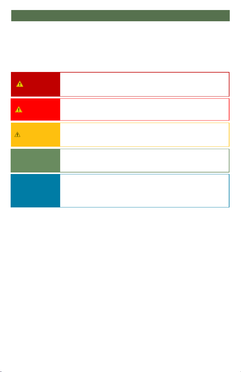
6.0 Warning Labels ...................................................................................... ix
6.1 Warning Labels ..................................................................................................... ix
6.2 Limited Liability..................................................................................................... ix
6.3 Testing...................................................................................................................... ix
7.0 Design and Function ............................................................................. 1
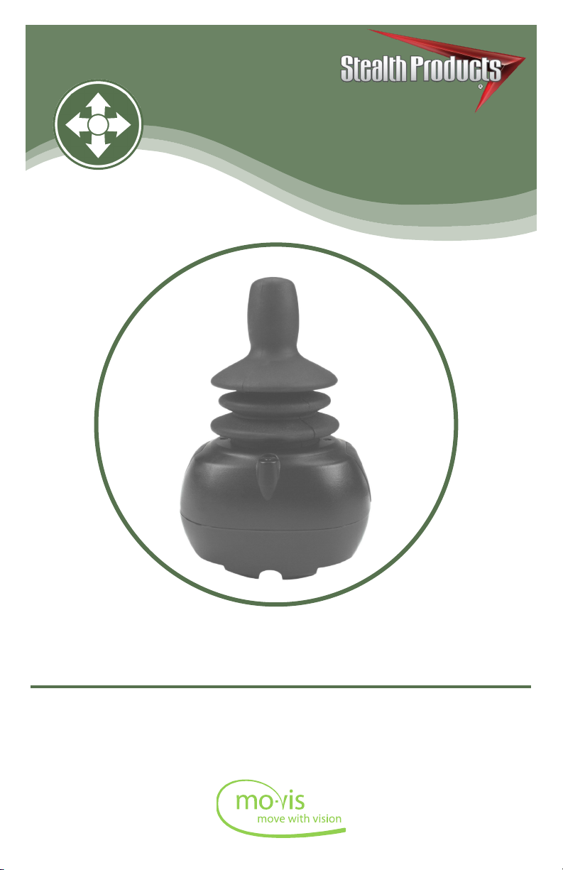
7.1 Purpose .................................................................................................................... 1
7.2 Features .................................................................................................................... 1
7.3 Mounting.................................................................................................................. 1
8.0 Parts And Accessories............................................................................ 2
8.1 All-Round/All-Round Lite Joystick Package ............................................... 2
8.2 All-Round/All-Round Lite Joystick Accessories......................................... 2
8.3 All-Round/All-Round Lite Joystick Unit Detail .......................................... 3
8.4 Custom Configurations....................................................................................... 3
9.0 Functioning ............................................................................................. 4
9.1 Intended Use ...........................................................................................................4
9.2 Joystick Safety ........................................................................................................ 5
9.3 Safe Driving............................................................................................................. 5
10.0 Installation Instructions ...................................................................... 6
10.1 Preparations.......................................................................................................... 6
10.2 Tools ........................................................................................................................ 6
10.3 Installation Plan................................................................................................... 6
11.0 All-Round/All-Round Lite Joystick Installation............................... 7
11.1 Installation............................................................................................................. 7

vi
Table Of Contents 5.0
12.0 Defining Position.................................................................................. 8
12.1 Defining Parameter Settings ..................................................................... 8
12.2 Parameter Settings ........................................................................................ 8
13.0 Satellite Twister Installation ............................................................... 9
14.0 Q-Logic™ Setup.................................................................................. 10
15.0 Q-Logic™ Joystick Setup .................................................................. 12
15.1 Q-Logic 2 ........................................................................................................12
Joystick Setup................................................................................................ 12
Center Deadband ........................................................................................ 12
Axis Deadband.............................................................................................. 12
Tremor Suppression ................................................................................... 13
Assign Direction Function ........................................................................ 13
Switch Operations ....................................................................................... 14
Joystick Calibration ..................................................................................... 14
Joystick Throw............................................................................................... 15
15.2 Q-Logic 3.......................................................................................................... 15
Joystick Setup ...............................................................................................15
Joystick Calibration.....................................................................................16
Joystick Throw ..............................................................................................16
Assign Direction...........................................................................................16
Center Deadband ........................................................................................ 17
Tremor Suppression ...................................................................................17
Switch Operation.........................................................................................17
16.0 R-Net™ Setup ..................................................................................... 18
16.1 R-Net™ Omni Setup.................................................................................... 18
16.2 Joystick Calibration...................................................................................... 19
16.3 R-Net™ Proportional Joystick Setup .................................................... 20
16.4 Throw................................................................................................................ 20

vii
Table Of Contents 5.0
16.5 Axis Orientation .............................................................................................. 21
16.6 Center Deadband........................................................................................... 21
17.0 mo-Vis Configurator Software ......................................................... 22
17.1 Software Capabilities................................................................................... 22
17.2 Software Download...................................................................................... 22
18.0 Testing ................................................................................................. 28
18.1 Check All-Round/All-Round Lite Joystick............................................ 28
18.2 Operational Test............................................................................................ 28
18.3 Test Drive ......................................................................................................... 29
18.4 Stop Test........................................................................................................... 29
19.0 Error Codes.......................................................................................... 30
19.1 Joystick Data ................................................................................................... 30
20.0 Fault Logs ............................................................................................ 31
21.0 Settings ................................................................................................ 32
21.1 Parameter Settings....................................................................................... 32
21.2 Mounting Settings........................................................................................ 32
21.3 Deadband Settings....................................................................................... 33
21.4 Tilt ....................................................................................................................... 33
21.5 Compensation Mode................................................................................... 34
21.6 Compensation Factor.................................................................................. 36
22.0 First Time Use ..................................................................................... 37
22.1 Dealer Assistance.......................................................................................... 37
22.2 User Testing .................................................................................................... 37
22.3 Conditions of Use ......................................................................................... 37
23.0 Maintenance........................................................................................ 38
23.1 Cleaning............................................................................................................ 38
23.2 Joystick Knob.................................................................................................. 38

viii
Table Of Contents 5.0
23.3 Monthly Check ............................................................................................... 38
23.4 Maintenance Free.......................................................................................... 38
24.0 Technical Data..................................................................................... 39
24.1 Product Description & Code .................................................................... 39
24.2 Joystick Connectors...................................................................................... 39
24.3 Dimensions ...................................................................................................... 39
24.4 Required Force ............................................................................................... 39
24.5 EMC Requirements ....................................................................................... 40

ix
Warning Labels 6.0
Warning Labels 6.1
Warnings are included for the safety of the user, client, operator and property. Please
read and understand what the signal words SAFETY, NOTICE, CAUTION, WARNING
and DANGER mean, how they could affect the user, those around the user, and property.
Limited Liability 6.2
Stealth Products, LLC accepts no liability for personal injury or damage to property that
may arise from the failure of the user or other persons to follow the recommendations,
warnings, and instructions in this manual.
Stealth Products does not hold responsibility of final integration of final assembly of
product to end user. Stealth Products is not liable for user death or injury.
Testing 6.3
Initial setup and driving should be done in an open area free of obstacles until the user is
fully capable of driving safely.
The All-Round/All-Round Lite Joystick should always be tested without any person sitting
in the wheelchair until every alteration of the physical installation or adjustment of the
joystick is complete.
NOTI CE
Identifies important information not related to injury, but
possible property damage.
SAFETY
Indicates steps or instructions for safe practices, reminders of
safe procedures, or important safety equipment that may be
necessary.
CAUTION Identifies a potential situation which (if not avoided) will
result in minor to moderate injury,and property damage.
WARNING Identifies a potential situation which (if not avoided) will
result in severe injury, death,and property damage.
DANGER Identifies an imminent situation which (if not avoided) will
result in severe injury, death,and property damage.

1
Design And Function 7.0
Purpose 7.1
The All-Round Lite Joystick has the same specifications as the standard All-Round
Joystick. They are compact joysticks that require more force than the Micro or Multi
Joysticks and are also used as a proportional joystick controlled by the hand, chin, or as
an attendant joystick.
Features 7.2
The All Round and All-Round Lite Joystick’s features include:
Fully proporonal and compact with medium throw & force.
The standard All-Round joysck requires 249g (.55lbf)
The All-Round Lite joysck requires 120g (.26lbf) of force.
Can be used as an aendant joysck, or controlled by the chin.
Linkable with one or two switches: on/o (pwr) and mode (in) with any 1/8” (3.5mm) jack.
All-Round Lite has lighter spring, therefore requiring less force to acvate, as well as
shorter throw.
Fully adjustable to individual possibilies.
Easily congurable with the free mo-Vis Conguraon Soware.
R-Net™,Q-Logic™, Curs, and Pilot + compable.
Mounting 7.3
The All-Round/All-Round Lite Joystick can be mounted at any location on the
wheelchair1:
By aaching the Power Chin Boom2 to the chair, the All-Round/All-Round Lite Joysck can
be used as a chin joysck.
Compable with Stealth’s joysck mounts3 including:
- The Swing-Away SM660-M
- The GAT472P-M mount for the GAT400 Series
- The ARMS260 Series
1. The All-Round/All-Round Lite Joystick is compatible with any existing mount.
2. A 6mm Mounting Set is required to mount the All-Round/All-Round Lite Joystick to the Power Chin Boom.
3. The All-Round/All-Round Lite Joystick is similar to the Permobil Compact Lite joystick.

2
Parts and Accessories 8.0
All-Round/All-Round Lite Joystick Package 8.1
An All-Round/All-Round Lite Joystick package consists of the following parts:
Product Description Product Code
All-Round/All-Round Lite
Joystick set, with
integrated cabling
IDM-ALLROUND-9
IDM-ARLITE-9
All-Round/All-Round Lite Joystick Accessories 8.2
For mounting and further personalization, the following accessories are available:
Product Description Product Code
All-Round/All-Round Lite
Joystick Knob (ships with
joystick, can be ordered
separately if needed)
IDM-16
All-Round/All-Round Lite
Joystick Ball (must be
ordered separately)
IDM-30
Satellite Twister (including
All-Round/All-Round Lite
insert) (must be ordered
separately)
(Red) IDM-17
(Black) IDM-18
(Yellow) IDM-19
(Blue) IDM-20
(Green) IDM-21

3
Parts and Accessories 8.0
All-Round/All-Round Lite Joystick Unit Detail 8.3
The connections of the All-Round/All-Round Lite Joystick unit have protective
covers to avoid the intrusion of dust or moisture during usage.
CAUT IO N
Always put or keep the protective cover in a case the connections are not used.
When in use, a blue LED light on the All-Round/All-Round Lite Joystick indicates
the proper functioning of the unit. In case of an error, the LED flashes.
The light indicates the front of the joystick.
Please see “Error Codes” for a list of blinking light indications. (Section 19.0)
Custom Configurations 8.4
Stealth has the ability to create custom configurations for our mounting
hardware in order to create the best possible fit for the client.
NOTICE
Before inserting a connector, remove the protective cover.

4
Functioning 9.0
Intended Use 9.1
The All-Round/All-Round Lite Joystick are joystick modules which can be
connected directly to the wheelchair electronics with the Omni display or
Q-Logic™ display.
The All-Round/All-Round Lite Joysticks are a compact, proportional joysticks
which requires medium force and movement.
All-Round Joysck: 249g (.55lbf)
All-Round Lite Joysck: 120g (.26lbf)
WARNING
The joystick operates with high sensitivity. Protect the joystick against bumps. A
good movement coordination and force control is required.
WARNING
Do not use on surfaces that you are unsure of. Always follow instructions
provided by the wheelchair manufacturer about driving on safe surfaces, angle
of ascent, and angle of descent.
WARNING
Do not use the joystick as only support for your hand or limbs. Movements and
shocks may disrupt controls.

5
Functioning 9.0
The movements of the joystick are translated into according movements of the
wheelchair, driving, or menu navigation.
Common practice to navigate the wheelchair with the All-Round/All-Round Lite
Joystick is as follows:
Direcon: point the joysck into the direcon you want the wheelchair to move. The
wheelchair then moves in that direcon.
Speed: the further you move the joysck from the default (center) posion, the faster the
wheelchair moves.
Stop: whenever you release the joysck, the joysck moves back to the default (center)
posion and the wheelchair stops.
Joystick Safety 9.2
Do not use if the joysck handle is damaged, missing, or cracked.
Do not use if the joysck does not return to neutral posion independently.
Do not use if the joysck does not move to and from neutral posion smoothly.
In order to change the top of the joysck, gently pull on the top unl it lis o of
the metal rod. Place the round ball top (IDM-30) on metal rod unl rmly in place.
Safe Driving 9.3
It is mandatory to have a wheelchair power on/off switch, which immediately
shuts down the wheelchair power and electronics, and is within easy reach of
the user while driving. This allows the user to instantly stop the wheelchair in
case of problems or an emergency.
WARNING The on/off switch must be available to the user at all times.
In case the wheelchair responds in an unexpected way, the user must
immediately release the joystick or use the power on/off switch.

6
Installation Instructions 10.0
Preparations 10.1
Only a qualified service technician may install the All-Round/All-Round Lite
Joystick.
WARNING
An incorrect programming of the wheelchair electronics may cause damage to
the devices or injury to the user.
Tools 10.2
Use the proper tools to install and adjust the All-Round/All-Round Lite Joystick
to the desired mounting hardware.
CAUT IO N
The use of improper tools may cause damage to the device.
Installation Plan 10.3
Set up an installation plan before beginning the installation. This plan should
take into account:
Where the All-Round/All-Round Lite Joysck should be placed.
How the All-Round/All-Round Lite Joysck will be operated: by hand, chin, or aendant.
The posioning of the joysck. Do not place the joysck where it may be obstructed
from moving in any direcon.
CAUT IO N
Any connection must always be secured with all delivered screws. Only use the
screws provided in the package.

7
All-Round/All-Round Lite Joystick Installation 11.0
Installation 11.1
1. Place and secure all cabling on the wheelchair with the desired mounng hardware
package previously ordered.
WARNING
Make sure that cabling is mounted in such a way that excessive wear and
tear is avoided.
2. If required, place a power on/o (pwr) and/or mode (in) switch, secure their cabling, and
insert their connecons.
3. Connect the cabling to the wheelchair electronics.
CAUT IO N
Before inserting a connector, remove the protective cover. Keep the protective
cover in case connections are used.
WARNING All wheelchair electronics must be switched off.

8
Defining Position (Parameters) 12.0
If the All-Round/All-Round Lite Joystick is not mounted with the USB
connection pointing towards the user, you can adjust the joystick direction in
steps of 90° with the mo-Vis Configurator Software.
This soware must be installed and ready to use on a pc.
Depending on your prole (user, aendant, dealer, OEM), you will be able to change
a number or parameter sengs.
To dene the movements during the installaon procedure, we advise having at least
a dealer prole.
An interface box is not aached at the end of the cable, it is built into the joysck. The
All-Round/All-Round Lite is not calibrated. By running the diagnosc eld test with the
Conguraon Soware, the joysck can be calibrated in order to meet the specic needs of
the customer.
Defining Parameter Settings 12.1
To define parameter settings, proceed as follows:
Connect the All-Round/All-Round Lite Joysck to a pc. Use a standard mini-USB cable.
Congure the parameters with the soware.
Upload the conguraon.
Test the conguraon and adjust if necessary.
Parameter Settings 12.2
Please see “Settings” for a list of all parameter settings. (Section 21.0)
The mo-Vis Congurator Soware is oponal to download. The joysck and its sengs can
be congured through the chair’s display.

9
Satellite Twister Installation 13.0
You can mount one or two Satellite Twisters1to the All-Round/All-Round Lite
Joystick.
1. Dene the locaon of the Satellite Twisters: le, right, or on both sides.
2. Unscrew and remove the cover for the Satellite Twister connecon with a
Phillips screwdriver.
3. Place the Satellite Twister rmly into the open slot.
4. Use the screw of the cover to secure the Satellite Twister to the All-Round/All-Round Lite
Joysck.
5. If required, place a second Satellite Twister in the same way.
6. Connect the cabling of the Satellite Twister to the All-Round/All-Round Lite Joysck.
CAUT IO N
Tighten the screws firmly, but not excessively. Excessive force may damage
the unit.
1. The Satellite Twister comes with a special All-Round/All-Round Lite insert. This ts only into
the housing of the All-Round/All-Round Lite Joysck.

10
Q-Logic™ Setup 14.0
Q-Logic™ Programmer Setup
Bookmark Buttons
Select Options in the main
menu. Button actions are
displayed on screen above
corresponding buttons. In
other menus hold button to
bookmark settings, and press
button to quickly go to
bookmark.
Navigation
Arrows navigate the main
menu. Up & Down to navigate
the menus, Right
to open a menu item and Left
to return to previous menu.
NOTE: Q-Logic™ Enhanced
Display and Q-Logic™
Handheld Programmer
required.
Plus & Minus
Toggle settings or changes
values of the highlighted
parameter.
Help Button
Displays information about
options selected on screen.
Other manuals for mo-Vis Series
1
This manual suits for next models
4
Table of contents
Other Stealth Wheelchair manuals
Popular Wheelchair manuals by other brands

Rehab
Rehab HD Balance User manual & assembly instructions

Invacare
Invacare 9000 series Owner's operator and maintenance manual

Pride Mobility
Pride Mobility IGO Fold owner's manual

Specialised Orthotic Services
Specialised Orthotic Services Miko user manual

Days
Days VERB user manual

Valex
Valex M-MU 18-MULTI ONE instruction manual