m-Dimension 12WA7N User manual

DC to AC Power Inverters
Pure Sine Wave Output
Owner’s Manual
MODELS:
12WA7N
12WA10N
®

2 Form 122175
TABLE OF CONTENTS
Section 14 Warranty …………………………………………………………………….. 15
Section 13 Appendix …………………………………………………………………… 14
Section 12 Accessories ……………………………………………………………….. 14
Section 11 Troubleshooting …………………………………………………………. 13
DC Input Wiring Diagram …………..……...………………………. 10
Section 9 Overall Wiring Diagram …………………………...…………….…… 11
Physical Description ………………………………………………………. 6
Section 7 Remote "On/Off" Switch …………………………...……………….. 9
Section 5 Inverter Mounting …………………….………………………………. 8
Section 3 Nomenclature ………………………………………..…………………… 5
Section 6 DC Wire Gauge & Fusing …………..……...………………………. 9
Section 4
Section 2 S
p
ecifications ……………………………….…….……….…………….. 4
Section #
Section 1 Safety Instructions …………………………………….………………. 3
Pa
g
e #Description
Section 10
T
heory of Operation ………………...……………………………….… 12
Section 8

3 Form 122175
1. SAFETY INSTRUCTIONS
IMPORTANT: Read this manual before installation, it contains important safety,
installation, and operating instructions. Save this manual and keep it in a safe place.
Sensata Technologies is an ISO 9001:2008 Registered Company
1.1 Inverter Safety Instructions:
•Warning: Power Inverters produce hazardous voltages. To avoid risk of
harm or fire, the unit must be properly installed.
•Warning: There are no user serviceable parts inside, do not remove the
cover.
•Warning: Power Inverters should not be mounted in a location that may be
exposed to rain or spray.
•Warning: Power Inverters should not be installed in a zero clearance
enclosure.
•Warning: Damage to the Power Inverter will occur if correct polarity is not
observed when installing the inverter’s DC input cables.
•Warning: Damage to the Power Inverter will occur if an external AC power
source is applied to the inverter’s AC hardwire output.
•Warning: Power Inverters contain a circuit breaker and capacitor that may
produce a spark. Do not mount in a confined battery or gas compartment.
•Warning: Be sure the Power Inverter is turned OFF during installation.
1.2 Battery Safety Information:
•Warning: Working in the vicinity of lead-acid batteries is dangerous. There
is a risk of acid exposure.
•Warning: Batteries generate explosive gases during operation.
•Warning: There is risk of high current discharge from shorting a battery that
can cause fire and explosion. Use insulated tools during installation.
•Warning: Remove all rings, watches, jewelry or other conductive items
before working near the batteries.
•Warning: Inspect the batteries once a year for cracks, leaks or swelling.
•Warning: Dispose of the batteries according to local regulations. Do not
incinerate batteries; risk of explosion exists.

4 Form 122175
2. TECHNICAL SPECIFICATIONS
2.1 Other Design Features: Patented construction and cooling methods
with thermally controlled cooling fan, local GFCI outlet protection, and Remote “On/Off”
switch hookup.
2.2 Unit Protection: Automatic electronic short circuit/overload protection,
Automatic over temperature shutdown and Output circuit breakers.
2.3 Battery Protection: Automatic low battery shutdown at 10.5VDC
(with in-rush delay.)
2.4 Usage: Any 120 VAC, 60 Hz single phase product within the inverter’s
power rating.
INVERTER MODEL 12WA7N 12WA10
Dimensions - LxWxH (Inches):
Efficiency:
Input Current (Amps DC): Up to 70 Up to 100
Input Volta
g
e (Volts DC):
Operatin
g
Temperature:
Output Current (Amps AC): Up to 5.8 Up to 8.3
Output Frequency (Hz):
Output Power (Watts): 700 1000
Output Volta
g
e (Volts AC):
Output Waveform:
Peak Output (Amps AC): 11 16
Wei
g
ht (Lbs): 25 26
DC POWER PORT: "P1"
12VDC Output Yes Yes
TRANSFER RELAY: "T"
Current Ratin
g
(Amps AC):
T
ransfer Time (milliseconds):
OPTIONAL
15
Less than 16 typical
60 + .05%
120 + 5%
Pure sine with < 5% THD
OPTIONAL
10.5 x 12 x 4
Up to 88%
11 to 14
-4°C to 40°C (20°F to 104°F)

5 Form 122175
3. NOMENCLATURE
-
Input Voltage: 12 = 12VDC
DI = Dimensions Inverters; Other Suffixes designates private label customer
Pure Sine Signal Output
Output Wattage: 7 = 700-watt; 10 = 1000-watt
Chassis Designation: W
A
N
3-Letter Suffix Designation
Base Model
DI 12 W
A
7

6 Form 122175
4. PHYSICAL DESCRIPTION
FIGURE 1: Inverter physical description
(1) GFCI Outlets: 120VAC Output.
(2) LED Status Control Panel: Provides inverter status (See figure 2 on page 7)
(3) Output Breaker: Trips to protect the inverter’s internal circuitry from shorted
AC loads or overload situations.
(4) Cooling Fan: Thermally-controlled fan triggers only when necessary to cool
down inside electronics.
(5) DC Field Wiring Compartment: Provides access to the Positive (+) &
Negative (-) DC input lugs.
(6) DC input Openings Positive (+) & Negative (-): Allows the DC input
cables to reach the DC lugs inside the field wiring compartment.
(7) Bonding Lug: Connects to the ground system.
(8) Remote ON/OFF: Wire through a remote On/Off switch, fuse, and then to
the positive side of the battery. Allows for remote control of the inverter.
Front View
6
1
5
2
4
3
7
8
Left Rear
Corner View

7 Form 122175
FIGURE 2: Control Panel Description
(1) External power: The Green LED indicates that there is an external AC power
line applied to the inverter AC input (early models only.)
(2) Inverter power “On”: The Green LED indicates that the inverter is operating
from batteries in inverter mode.
(3) Low battery: The Red LED indicates that the inverter is in a low battery
voltage condition and will shutdown.
(4) Overload: The Red LED indicates that the inverter is in an overload condition
and will shutdown.
(5) High Temperature: The Red LED indicates that the inverter is operating on a
high temperature condition and will shutdown.
(6) Local On/Off Switch: Switches the inverter ON/OFF.
1364 52

8 Form 122175
5. MOUNTING THE INVERTER
Note:
Before mounting the inverter system, read the safety
instruction section on page 3.
5.1 Tools for Installation: The following tools are needed for inverter
installation: Crimper, Cable ties, Cutter, Drill, # 2 Phillips Screw driver, Tape measure,
Wire cutters, Wire Strippers.
5.2 Mounting Recommendations:
FIGURE 3: Inverter mounting footprints (dimensions are in inches)
Note: The inverter mounting location should provide adequate
ventilation and clearance to maintain room temperature during
operation. At least 1/2 inch of clearance is required on all sides.
1Locate a suitable, secure vertical or horizontal mounting surface as close to the
batteries as possible without being in the same airtight compartment.
2If mounting the inverter on a vertical surface, it is recommended that the front
control panel be pointing down whenever possible.
3Locate the mounting holes on the chassis flanges and fasten them using ¼ inch
diameter screws to secure the inverter.
0.400.40 12.00

9 Form 122175
6. DC WIRE GAUGE & FUSING
6.1 Inverter Cable: An “inverter cable” kit (positive cable, negative cable and
proper fuse) is needed to connect the inverter to a battery bank. An 8-gauge cable is
also needed to connect the inverter’s bonding lug to ground.
The inverter cable length and the size of the inverter will determine the cable
gauge and the fuse size to use. The maximum inverter cable recommended is 20-ft; it
must be fused within 18-in from the positive (+) terminal of the battery.
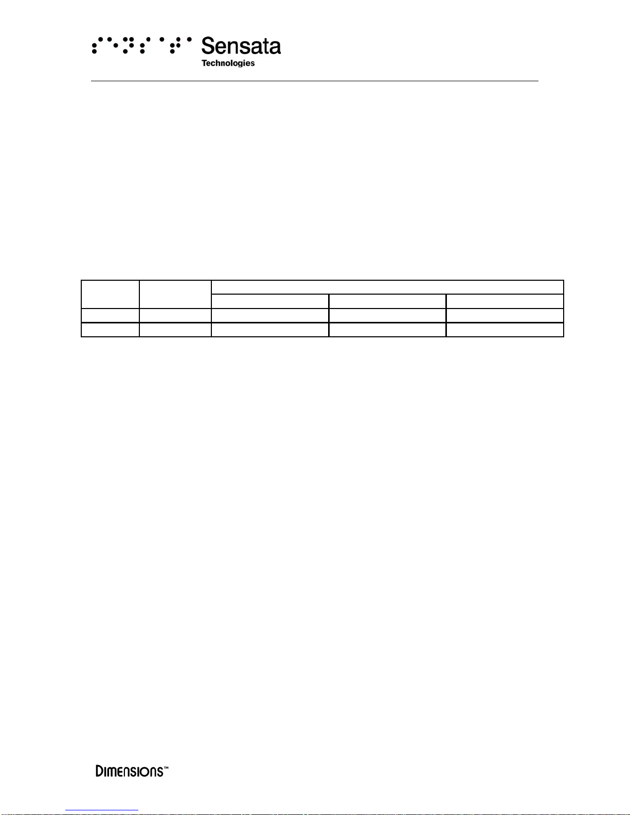
Cross reference the inverter model, and the estimated cable length in Table I to
determine proper cable gauge, and fuse size. The inverter cable kit can be purchased
directly from factory. See the accessories section on this manual.
Table I: Cable and Fusing Guide at 5% Voltage Drop at Full Output
Warning:
Proper cable gauge must be used to prevent excessive
voltage drop at the inverter DC input.
6.2 Cable Recommendations: To furnish an “inverter cable” kit, follow
below recommendations:
1Use stranded copper cables in all cases.
2Use SGX cross-linked polyurethane insulation type that complies with the high
temperature insulation requirements (125°C.) of SAE J-1127 and vehicle
manufacturer requirements.
3Cable gauge recommendations are minimum. For higher than normal temperature
applications or large motor loads and other applications with high surge currents use
cable gauge 1 to 2 sizes larger than recommended on table I above.
4Keep the cable lengths between battery and inverter as short as possible.
5Use Bussmann fuse type ANN or ANL and fuseblock # 3576. See the accessories
section on this manual.
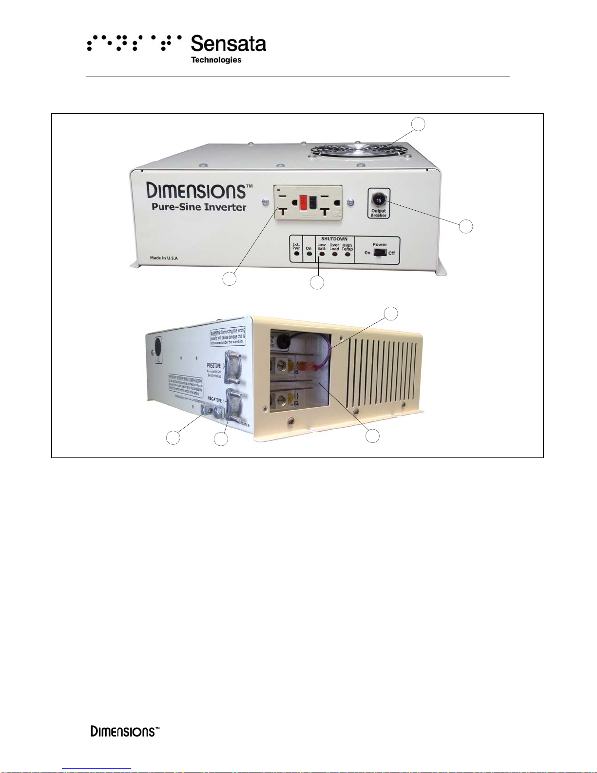
7. REMOTE “ON/OFF” SWITCH
An optional customer supplied remote “On/Off switch” can be connected to the
remote On/Off switch hookup lead located in the DC field wiring compartment. Use an
18-gauge cable, single pole single throw switch and a 5-Amp in-line fuse installed within
18-in from the positive (+) terminal of the battery.
Inverter Full Load
Model (Amps DC) 1' to 10' 11' to 15' 16' to 20'
12WA7N 70 6-
g
au
g
e, 150A fuse 4-
g
au
g
e, 200A fuse 2-
g
au
g
e, 250A fuse
12WA10N 100 4-
g
au
g
e, 200A fuse 2-
g
au
g
e, 250A fuse 1/0-
g
au
g
e, 350A fuse
Inverter to Battery Estimated Cable Len
g
th in Feet

10 Form 122175
8. DC INPUT WIRING DIAGRAM
FIGURE 4: Inverter Cable Assembly and Remote On/Off Switch Assembly Kit
Cable Connection Procedure
1) Remove the in-line fuses from the fuse-holders for cable installation.
2) Connect the inverter’s bonding lug to ground or vehicle chassis.
3) Connect the “inverter cable” set to the appropriate DC input lugs. Tight the strain relief to hold the cables in place.
4) Connect the ring terminated ends of the “inverter cable” set directly to the appropriate battery post.
Make sure the battery polarity is observed.
5) Connect the load side of the “remote On/Off” switch to the cable lead extending from the inverter and the
fused side to the positive post of the battery.
6) Install the in-line fuses removed in step (1) in the fuse-holders. A typical one time spark will occur when this final
connection is made. Plug the flat cable to the back of the remote panel for inverter operation.
2
2
3
3
8-gauge
1/4" Ring
Terminal
18"
Fuseholder
Fuse
20' Maximum, Red Cable: Positive (+)
20' Maximum, Black Cable: Negative (-)
3/8" Ring
Terminals
1
4
4
POS.
NEG.
Fast on
AC Output
Note: unscrew the inverter’s face
plate to access the DC lugs
Fuse & Fuseholder
On/Off Switch
18-gauge
5-Amp
Single Pole
Single Throw
Remote “On/Off Switch” - Customer supplied option
18" 5
1
Red/Violet Cable
3
3
5
Rear View
Side View

11 Form 122175
9. OVERALL WIRING DIAGRAM
FIGURE 5: Typical AC & DC wiring diagram – Auxiliary battery configuration

12 Form 122175
10. THEORY OF OPERATION
The “Local On/Off Switch” located on front, or the “Remote On/Off Switch” if
used controls the inverter. Both the Local and “Remote On/Off” switches are configured
in series. To control the inverter remotely set the “Local On/Off switch” to ON.
Inverter Power Mode: The green LED “On” will come on. The AC power produced
by the inverter comes from the energy stored in the battery bank through a
sophisticated electronic inversion process. A transformer, a Metal Oxide Silicon Field
Effect Transistors (MOSFET), a filter capacitor and a 16-bit, 16 MHz microprocessor
control are used to generate clean useful AC power.
Note:
The signal output waveform produced by the inverter when in
“inverter mode” is pure sinusoidal. It has a total harmonic distortion of
less than 5%.

13 Form 122175
11. TROUBLESHOOTING
Call or e-mail customer service for free consultation during business hours (central time)
at: 1-800-553-6418; 1-651-653-7000; fax: 1-888-439-3565; 1-651-653-7600
1) No AC output power:
1.1) No LEDs on:
•Check in-line fuse which is located within 18” from the battery’s positive post.
•DC connections to be tight and clean.
•Battery voltage to be above 9 VDC.
•Bypass or disconnect remote On/Off switch if used.
1.2) Green LED “Inverter Power” on: Disconnect all loads and connect a test
light to the GFCI output outlet (make sure all breakers are reset)
•If test light is on: Check your AC connections and loads.
•If test light is off: Possible bad GFCI or transfer relay
1.3) Green LED “External Power” on: Repeat 1.2 steps above.
2) Red LED “Low Battery” on: The use of battery isolator is not recommended
due to excessive voltage drop across terminals
•Battery voltage to be above 10.5 when vehicle’s engine is OFF, and above 13
VDC when it is ON.
•Check for proper DC wire gage (see wire gauge & fusing section)
3) Red LED “Overload” on: Unplug all loads, and reset the inverter On/Off:
•If the overload condition persist, possible bad inverter.
•Overload conditions clears, check for short circuits or check load size versus
inverter output wattage size.
4) Red LED “High Temp.” on: Let the inverter to cool down to 40°C (104°F)

14 Form 122175
12. ACCESSORIES
ADI Part
Number
Item Description
430011 Fuse 100A, ANN-250
430052 Fuse 150A, ANN-150
430054 Fuse 350A, ANN-350
430010 Fuse 200A, ANN-200
431021 Fuse holder with cover
611096 Inverter cable assembly 10ft, 4-gauge, 200A fuse and fuse holder
611089 Inverter cable assembly 15ft, 4-gauge, 200A fuse and fuse holder
611103 Inverter cable assembly 10ft, 6-gauge, 150A fuse and fuse holder
611034 Inverter cable assembly 15ft, 2-gauge, 250A fuse and fuse holder
611022 Inverter cable assembly 20ft, 2-gauge, 250A fuse and fuse holder
611100 Inverter cable assembly 20ft, 1/0-gauge, 350A fuse and fuse holder
611348 Remote lighted rocker switch kit with fuse and 14ft 18-gauge cable (dash mount)
611522 Remote switch panel kit with fuse and 14ft 18-gauge cable (electrical box mount)
140004 Battery box single group 31
250018 Ventilation assembly (battery box) 42in long
13. APPENDIX
Battery Specifications Chart
Group Voltage Capacity Weight
Number Volts DC Amp-Hour L W H LBS
GC2 6 220 10
3/8
7
3/16
10
5/8
70
L16 6 350 11
3/4
7
1/8
16
3/4
125
27/31 12 95 13 6
13/16
9
7/16
70
4D 12 180 20
3/4
8
3/4
9
7/8
140
8D 12 225 20
3/4
11
1/8
9
7/8
170
Dimensions in inches
Note: The use of deep-cycle batteries is strongly recommended on
inverter applications; deep discharge cycles typical with inverter
applications can shorten the life of other type of batteries.
Sensata Technologies
Power Controls White Bear
4467 White Bear Pkwy,
St. Paul, MN 55110-7626
Tel: 800-553-6418
Fax: 651-653-7600
http://dimensions.sensata.com

15 Form 122175
Limited Warranty Terms & Conditions
SHIPPING TERMS: F.O.B. St. Paul Minnesota. Freight prepaid and billed, subject to prior credit approval.
MINIMUM ORDER: $50.00 Net Price
LOSS OR DAMAGE: Loss or damage in transit are the responsibility of the carrier. Any claim should be filed with the
delivering transport company. Invoice, Bill of Lading and Delivery receipt with damage noted therein must accompany any
claims for freight damage. Claims for shortage and lost shipments must be made in writing to Sensata Technologies,
Power Controls White Bear, St. Paul, MN within 10 days of date of shipment. Claims not reported within this time frame
will not be honored.
PRICES: Prices are subject to change without notice. All orders are subject to acceptance at the factory. We reserve the
right to invoice prices in effect at time of shipment.
TERMS: Net 30 days with approved credit, credit card or C.O.D.
RETURN GOODS POLICY:
• No returned materials will be accepted without an accompanying Returned Materials Authorization Number (RMA) from
the factory.
• Credit will be issued for returned goods to the original purchaser within 60 days of purchase, provided the inverter is
returned to Sensata unused and not mounted. The amount of credit will be issued at Sensata’s discretion based on the
condition of the product.
• Customer must be in good standing with Sensata Technologies.
• Inverters that are discontinued, high-voltage (over 24vdc), special-order or used are excluded and will not be eligible for
credit. Non-inverter items such as cable assemblies, fuses and fuse holders, will not be eligible for credit
• Support components supplied by Sensata vendors will be covered under that manufacturer’s credit return policy.
• Customer pays return freight.
PLEASE SHIP AUTHORIZED RETURNS TO:
Sensata Technologies | Power Controls White Bear | 4467 White Bear Parkway | St. Paul, MN 55110
Return Freight Prepaid
LIMITED WARRANTY:
Sensata Technologies extends the following warranty to the original purchaser of those goods subject to the qualifications
indicated. Sensata warrants to the original purchaser for use that the goods or any component thereof manufactured by
Sensata will be free from defects in workmanship from the date of purchase for the period listed on the product label,
provided such goods are installed, maintained and used in accordance with Sensata and the original manufacturer’s
written instructions. Damages caused by the misuse, undue care or obvious wear through use will not be covered by this
warranty.
Components not manufactured by Sensata, but used within the assembly provided by Sensata, are subject to the
warranty period as specified by the individual manufacturer of said component, provided such goods are installed,
maintained and used in accordance with Sensata and the manufacturer’s written instructions.
Sensata’s sole liability and the Purchaser’s sole remedy for a failure of goods under this limited warranty and for any and
all claims arising out of the purchase and use of the goods, shall be limited to the repair or replacement of the goods that
do not conform to this warranty.
To obtain repair or replacement service under the limited warranty, the purchaser must contact the factory for a Return
Material Authorization (RMA). Once obtained, send the Return Material Authorization Number along with the defective
part or goods to:
Sensata Technologies, Power Controls White Bear, 4467 White Bear Parkway, St. Paul, MN 55110. Return Freight Prepaid.
THERE ARE NO EXPRESS WARRANTIES COVERING THESE GOODS OTHER THAN AS SET FORTH ABOVE. THE IMPLIED
WARRANTIES OF MERCHANTABILITY AND FITNESS FOR A PARTICULAR PURPOSE ARE LIMITED IN DURATION TO ONE
YEAR FROM DATE OF PURCHASE.
SENSATA TECHNOLOGIES ASSUMES NO LIABILITY IN CONNECTION WITH THE INSTALLATION OR USE OF THE
PRODUCT, EXCEPT AS STATED IN THIS LIMITED WARRANTY. SENSATA TECHNOLOGIES WILL IN NO EVENT BE LIABLE
FOR INCIDENTAL OR CONSEQUENTIAL DAMAGES.
WARNING:
LIMITATIONS ON USE: DIMENSIONS®brand products are not intended for use in connection with Life
Support Systems and for Avionic use. Sensata Technologies makes no warranty or representation in connection with their
products for such uses.

16 Form 122175
4467 White Bear Parkway
St. Paul, MN 55110
Phone: 651-653-7000, 800-553-6418
Fax: 651-653-7600, 888-439-3565
www.dimensions.sensata.com
Form # 122175 03/25/2013
© Sensata Technologies 2013
Printed in U.S.A.
This manual suits for next models
1
Table of contents
Other m-Dimension Inverter manuals
Popular Inverter manuals by other brands

YASKAWA
YASKAWA VS-616G5 Series owner's manual

Kubota
Kubota WSM J Series Workshop manual

GSL
GSL SWB1000-12 operating instructions

YASKAWA
YASKAWA PVI 23 TL Installation and operation manual

Endress
Endress ESE 604 DHG DIN Translation of the original operating instructions

SMA
SMA SUNNY BOY STORAGE 3.8-US installation manual

Salicru
Salicru CV50-008-4F user manual

Schumacher Electric
Schumacher Electric BATTERY EXTENDER BE01257 owner's manual

Solectria Renewables
Solectria Renewables PVI 13KW Installation and operation manual

Huawei
Huawei SUN2000-50KTL-M0 user manual

Grundfos
Grundfos RSI Installation and operating instructions

REKOSER
REKOSER RSI-LF-3PH Series user manual