manuals.online logo
Brands
  1. Home
  2. •
  3. Brands
  4. •
  5. Steca
  6. •
  7. Inverter
  8. •
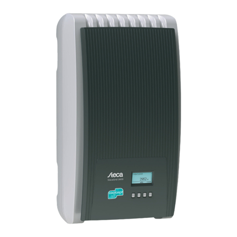
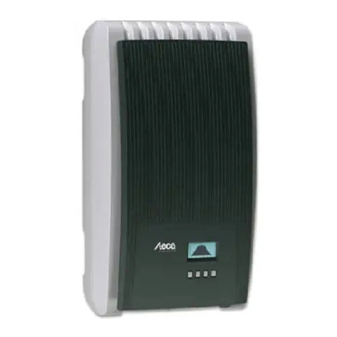
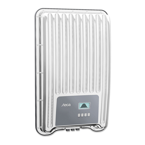
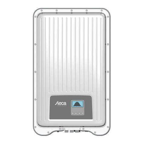
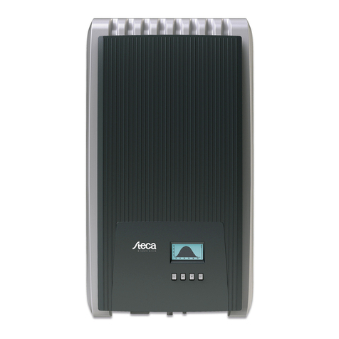
  9. Steca coolcept StecaGrid 1500 User manual

Steca coolcept StecaGrid 1500 User manual

753.493 I Z01 I 1450 1


About these instructions
The Abbreviated Installation Instructions provide the
installer with information on mounting, connecting
and commissioning the device.
The Abbreviated Installation Instructions contain
basic device operating information for the operator.
Detailed information is provided in the comprehen-
sive Installation and Operating Instructions, available
via the Internet.
Other sources of information are specified via Internet addresses and QR codes. Scan the
QR codes using a smartphone and suitable QR code app.
http://www.steca.com/Wechselrichter-Wohnsiedlung
Intended use
The coolcept family of products consists of inverters of different power classes, intended for indoor
or outdoor installation and for single-phase or three-phase feeding.
These inverters may only be used in grid-connected photovoltaic systems.
The inverter is suitable for use with all solar modules whose connections are not grounded.
All connected solar modules must be classified as Class A according to IEC 61730, because these
inverters do not have galvanic isolation.
The maximum system voltage of the photovoltaic generator must be higher than the AC grid volt-
age.
Connections for an optional energy storage system are provided on some models. The connector
must never be connected directly to a battery.
coolcept
coolcept-x
StecaGrid 1500 (-x)
StecaGrid 1800 (-x)
StecaGrid 2000 (-x)
StecaGrid 2300 (-x)
StecaGrid 2500 (-x)
StecaGrid 3000 (-x)
StecaGrid 3010 (-x)
StecaGrid 3600 (-x)
StecaGrid 4200 (-x)
coolcept3
coolcept3-x
StecaGrid 3203 (-x)
StecaGrid 4003 (-x)
StecaGrid 4803 (-x)
StecaGrid 5503 (-x)
EN
A
bbreviated Installation
Instructions
2 Abbreviated Installation Instructions
Safety
This document must be read and understood in full before installing and/or using the de-
vice.
Connection, commissioning and repair may only be performed by a qualified electrician
who is specially trained in solar technology.
If one of the following components is damaged, immediately take the device out of operation and
disconnect it from the grid and solar modules:
- Device (not functioning, visible damage, smoke, penetration of liquid etc.)
- Cables
- Solar modules
Do not switch on the system again until it has been repaired and checked by a suitably qualified and
authorised technical specialist.
Dangerous voltages can remain present on the components up to 10 minutes after switching off the
DC circuit breaker and the line circuit breaker.
Warning, there are 2 voltage sources present: the power grid and the solar modules.
Disconnect both voltage sources from the device before working on the device.
Do not cover the cooling fins.
The factory-applied labels on the device must not be modified or removed.
Do not open the device.
Keep children away from photovoltaic systems.
Follow the general and national safety and accident prevention regulations.
This document must be stored safely and be available for the entire service life of the device and
must be passed on to any subsequent user.
Signs and labels on the device
1Safety label with warning notices
2Type plate with the main technical data and serial number
When connecting external components (e.g. data logger): be sure to observe the
manufacturer’s instructions. Incorrectly connected components can damage the
device.
Incorrect operation or settings, especially during the initial commissioning proc-
ess, can reduce the yields of the system
Scope of delivery
coolcept
coolcept³
1
1
1
-
1
coolcept-x
coolcept³-x
1
1
1
3
1
1
2
3 Abbreviated Installation Instructions
Installation
Ensure that you do not impair the fire safety measures of the building when routing ca-
bles for the device.
Make sure that no inflammable gases are present.
Observe all applicable installation regulations and standards, national laws and connection values
specified by the regional power supply company.
Risk of death by electrocution!
- Switch off all AC line circuit breakers and secure them against being unintentionally switched on
again.
- Check that all pins of the AC cable are free of voltage.
- Set the DC circuit breaker on the inverter to position 0 and secure it against being unintentionally
switched on again.
- DC cables carry voltage when the solar modules are subjected to sunlight.
The mounting location and immediate environment must be: permanently fixed, vertical, flat, non-
inflammable and not subject to constant vibration. The mounting surface must be able to securely hold
the fastening screws.
Ensure conformance to the permissible ambient conditions.
Do not install the inverter in areas where animals are kept.
Observe the connection ratings specified on the type plate.
Lay the cables such that the connection cannot come loose accidentally.
Do not connect the DC cables to an earth potential.
1. Connect the AC plug to the grid cable as
shown (view of the cable connections).
http://www.wieland-electric.com/de/produkte/
rundsteckverbinder-geb%C3%A4ude
2. Connect the DC plugs to the solar module
cables, observing the correct polarity.
https://www.phoenixcontact.com/online/portal/de
160 mm 150 mm
240 mm160 mm
45 mm
270 mm
260 mm
320 mm
coolcept-x
190 mm
400 mm
*
*
*
*
*
CLICK
4 Abbreviated Installation Instructions
3. If present, plug in the TCP-IP (1) and SolUse (7) data connections.
4. If present, plug in the RS485 (2) data connection. Plug in any termination plugs that may be re-
quired.
5. coolcept-x and coolcept³-x only: close any open RJ45 sockets (1, 2) with the sealing caps provided.
6. Press the DC cable plugs into the DC connectors (4, 5) on the inverter (these click audibly into
place).
7. Plug the AC plug into the coupling (3) on the inverter (this clicks audibly into place).
8. Switch on the AC line circuit breaker. This switches on the inverter. The display shows the start
page for initial commissioning. Initial commissioning starts. A number of basic settings are queried
in a pre-defined sequence.
Detailed information on installation of the AC cables and the line circuit breaker is pro-
vided in the downloadable version of the Operating Instructions.
http://www.steca.com/Wechselrichter-Wohnsiedlung
9. Set the display language.
10. Set the date/time.
11. Set the country of use. Attention, the country can only be set once!
For detailed information on the country settings, see:
http://www.steca.com/coolcept-table-of-countries
Additional configuration may need to be entered, depending on the selected country.
12. Select Finish and press SET.
13. If the settings are incomplete then a dialogue stating Settings are incomplete is displayed.
Press SET and complete the missing basic settings.
14. When all settings have been made, a dialogue stating Are all settings correct? is dis-
played. To correct any settings: press ESC. To finish initial commissioning: press SET for a longer
period of time (> 1 s). If SET was pressed for a longer time then the inverter starts anew and syn-
chronises itself with the grid.
15. Switch on the DC circuit breaker (6) on the underside of the inverter.
The inverter is ready for operation.
In the case of questions or if more installation information is required, please refer to the
full Operating Instructions, which are available for download.
http://www.steca.com/Wechselrichter-Wohnsiedlung
Steca Elektronik GmbH
Phone:
+49 (0) 8331 8558-833
Mammostrasse 1
Fax:
+49 (0) 8331 8558-132
87700 Memmingen
Germany
Email:
[email protected]
5 Abbreviated Operating Instructions
Structure
coolcept/coolcept³
1Hood
2Display (monochrome, 128 x 64 pixels)
3Type plate, warning notices
4Operating buttons: ESC, , , SET (from left to
right)
5RJ45 sockets (RS485 bus)
6AC connection
7DC connection, Minus (−) for solar module
8DC connection, Plus (+) for solar module
9DC connection, Plus (+) for optional energy storage
system
10 DC circuit breaker (interrupts the plus and minus in-
puts simultaneously)
11 RJ11 socket (SolUse)
12 RJ45 socket (LAN)
13 DC connection, Minus (−) for optional energy stor-
age system
coolcept-x/coolcept³-x
1Hood
2Display (monochrome, 128 x 64 pixels)
3Type plate, warning notices
4Operating buttons: ESC, , , SET
5AC connection
6Pressure equalisation membrane
7RJ45 socket (RS485 bus)
8DC connection, Minus (−) for solar module
9RJ45 socket (RS485 bus)
10 DC connection, Plus (+) for solar module
11 RJ45 socket (LAN)
12 DC circuit breaker (interrupts the plus and minus in-
puts simultaneously, can be secured with a padlock)
13 Hole for optional ground or mechanical fastening
(safety chain)
Abbreviated Operating Instructions
6 Abbreviated Operating Instructions
Display
Example status display of the output power:
1Display label
2Measurement with units
3Date
4Symbol Non-confirmed event messages
5Animated symbol Connect (indicates data traffic on
the RS485 bus)
6Symbol Derating
7Symbol Fixed voltage mode activated
8Time
9IP address of the device when a network connection
has been established, display alternates with ③– ⑦
Operating buttons
Button
Action
Function
General information Guided configuration process
ESC Press briefly Jumps up by 1 menu level Navigates 1 step back
Discards changes
Press longer
(≥1 second)
Jumps to status display Jumps to the start of the
guided configuration process
Press briefly Moves the selection bar or the display content upwards
Moves the selection 1 position to the left when entering numeric
values
Increases the setting value by 1 step
Press briefly Moves the selection bar or the display content downwards
Moves the selection 1 position to the right when entering numeric
values
Decreases the setting value by 1 step
SET Press briefly Jumps down by 1 menu level -
A selected numerical value starts flashing and can be changed
Accepts any entered changes
Changes the state of a control element (check box/radio button)
Press longer
(≥1 second)
Answers a query dialogue with Yes
Navigates 1 step forward
Output power
7 Abbreviated Operating Instructions
Menu structure
Errors are indicated by a red flashing background. An event message is also displayed at the same time.
For detailed information on the menu structure and event messages, see:
http://www.steca.com/Wechselrichter-Wohnsiedlung
8 Abbreviated Operating Instructions
Example: Numerical and graphical display of the monthly yields
The status display is shown.
1. Press SET. The main menu is displayed with Yield selected.
2. Press SET. A list of yield periods (Day, Month, Year) is displayed.
3. Press  to select a yield period.
4. Press SET. The individual yields for the yield period are shown in
a list (Fig. left).
5. Press  to select an individual yield.
6. Press SET. The selected individual yield is shown in a chart
(Fig. left).
7. Press  to page through the charts.
8. Press SET to return to the list.
9. Yields can also be displayed as monetary values (remuneration)
(see menu structure).
The following data is stored in the inverter:
Event messages with date
Energy yields on a daily, monthly and annual basis
Energy yield data Storage resolution/period
10-minute values 31 days
Daily values 13 months
Monthly values 30 years
Annual values 30 years
Total yield Permanent
Data communication
For data analysis purposes, the inverter can provide a wide range of data via the RS485 and LAN data
interfaces (e.g. data logger). Multiple inverters can be interconnected via the RS485 bus.
For detailed information on data communication, see:
http://www.steca.com/Wechselrichter-Wohnsiedlung
Registration
Registration of the operator and the system at:
http://www.steca.com/portal
Care/Maintenance
Remove dust with compressed air (max. 2 bar).
Remove soiling with a slightly damp cloth (clear water or a 2% hard soap solution).

Other manuals for coolcept StecaGrid 1500

1

This manual suits for next models

10

Other Steca Inverter manuals

Steca coolcept fleX Series Manual

Steca

Steca coolcept fleX Series Manual

Steca StecaGrid 8 000+ 3ph User manual

Steca

Steca StecaGrid 8 000+ 3ph User manual

Steca XPC 1400-12 Use and care manual

Steca

Steca XPC 1400-12 Use and care manual

Steca coolcept StecaGrid 1500 User guide

Steca

Steca coolcept StecaGrid 1500 User guide

Steca coolcept StecaGrid 1800 User manual

Steca

Steca coolcept StecaGrid 1800 User manual

Steca coolcept3 StecaGrid 3203 User manual

Steca

Steca coolcept3 StecaGrid 3203 User manual

Steca AJ 275 Use and care manual

Steca

Steca AJ 275 Use and care manual

Steca coolcept StecaGrid 3000 User manual

Steca

Steca coolcept StecaGrid 3000 User manual

Steca coolcept User manual

Steca

Steca coolcept User manual

Steca Solarix PI 550 User manual

Steca

Steca Solarix PI 550 User manual

Steca Fronius Solarix 400 I User manual

Steca

Steca Fronius Solarix 400 I User manual

Steca Solarix PI 500-12 User manual

Steca

Steca Solarix PI 500-12 User manual

Steca Solarix 2020-x2 User manual

Steca

Steca Solarix 2020-x2 User manual

Steca coolcept User manual

Steca

Steca coolcept User manual

Steca StecaGrid 1900 Series User manual

Steca

Steca StecaGrid 1900 Series User manual

Steca StecaGrid 2010+ Slave User manual

Steca

Steca StecaGrid 2010+ Slave User manual

Steca stecagrid 300 User manual

Steca

Steca stecagrid 300 User manual

Popular Inverter manuals by other brands

enphase IQ8 Design guide

enphase

enphase IQ8 Design guide

YASKAWA L1000A Series Technical manual

YASKAWA

YASKAWA L1000A Series Technical manual

Mitsubishi Electric FR-F862 instruction manual

Mitsubishi Electric

Mitsubishi Electric FR-F862 instruction manual

Generac Power Systems Quietsource 004917-2 owner's manual

Generac Power Systems

Generac Power Systems Quietsource 004917-2 owner's manual

Champion Global Power Equipment 100515 Operator's manual

Champion Global Power Equipment

Champion Global Power Equipment 100515 Operator's manual

HP 8614A Operating and service manual

HP

HP 8614A Operating and service manual

Climma CWS INSTALLATION, USAGE AND MAINTENANCE MANUAL

Climma

Climma CWS INSTALLATION, USAGE AND MAINTENANCE MANUAL

Innova 2.0 15HP Installer manual

Innova

Innova 2.0 15HP Installer manual

Xantrex Freedom X 2000 owner's guide

Xantrex

Xantrex Freedom X 2000 owner's guide

DK-Technologies PT5300 Guide to installation and operation

DK-Technologies

DK-Technologies PT5300 Guide to installation and operation

Toshiba TOSVERT VF-S15 series instruction manual

Toshiba

Toshiba TOSVERT VF-S15 series instruction manual

OPTICLIMATE PRO3 Series Installation and user guide

OPTICLIMATE

OPTICLIMATE PRO3 Series Installation and user guide

Black & Decker BDPC400AU instruction manual

Black & Decker

Black & Decker BDPC400AU instruction manual

Generac Power Systems 004992-0, 004992-1 owner's manual

Generac Power Systems

Generac Power Systems 004992-0, 004992-1 owner's manual

Magnum Dimensions 24/3000H-3PH owner's manual

Magnum Dimensions

Magnum Dimensions 24/3000H-3PH owner's manual

Western Co W-HPT-3000 Quick installation guide

Western Co

Western Co W-HPT-3000 Quick installation guide

Champion Global Power Equipment 100519 Operator's manual

Champion Global Power Equipment

Champion Global Power Equipment 100519 Operator's manual

Mitsubishi Electric F800-E Series instruction manual

Mitsubishi Electric

Mitsubishi Electric F800-E Series instruction manual

manuals.online logo
manuals.online logoBrands
  • About & Mission
  • Contact us
  • Privacy Policy
  • Terms and Conditions

Copyright 2025 Manuals.Online. All Rights Reserved.