STEELON ANT 500 User manual

Automatic Sliding Gate Opener
Автоматика для відкатних воріт
User’s Manual
Посібник користувача

1
Contents
1. Summary········································(1)
2. Appearance and dimensions·························(1)
3. Parameters·······································(2)
4. Features of control board ···························(2)
5. Installation of mechanical parts·······················(2)
5.1 Installation of motor base plate ····················(2)
5.2 Installation of gate opener·························(3)
5.3 Installation of racks······························(3)
5.4 Installation of limit magnets·······················(3)
5.5 Function of clutch·······························(4)
6.Installation diagram of electrical parts··················(4)
7.Fuction setting····································(8)
8.Trouble Shooting··································(11)
9.Important Notes ································· (11)
1. Summary
This equipment is one of the auto gate openers launched by our company adopting a new design and
integrated control system. Our new sliding gate opener has many features such as: low noise, light weight,
powerful starting torque, stability, reliability and is compact and stylish. The motor will still work for a short
period of time using lower voltage. The control board has overload protection. When there is a power
failure, the motor drive can be separated by the use of the clutch, by using the specified key the user has the
ability to disconnect the clutch enabling the gate to be opened or closed manually. Using the optional
infrared photocells the gate will automatically stop and re-open if an obstacle is sensed.
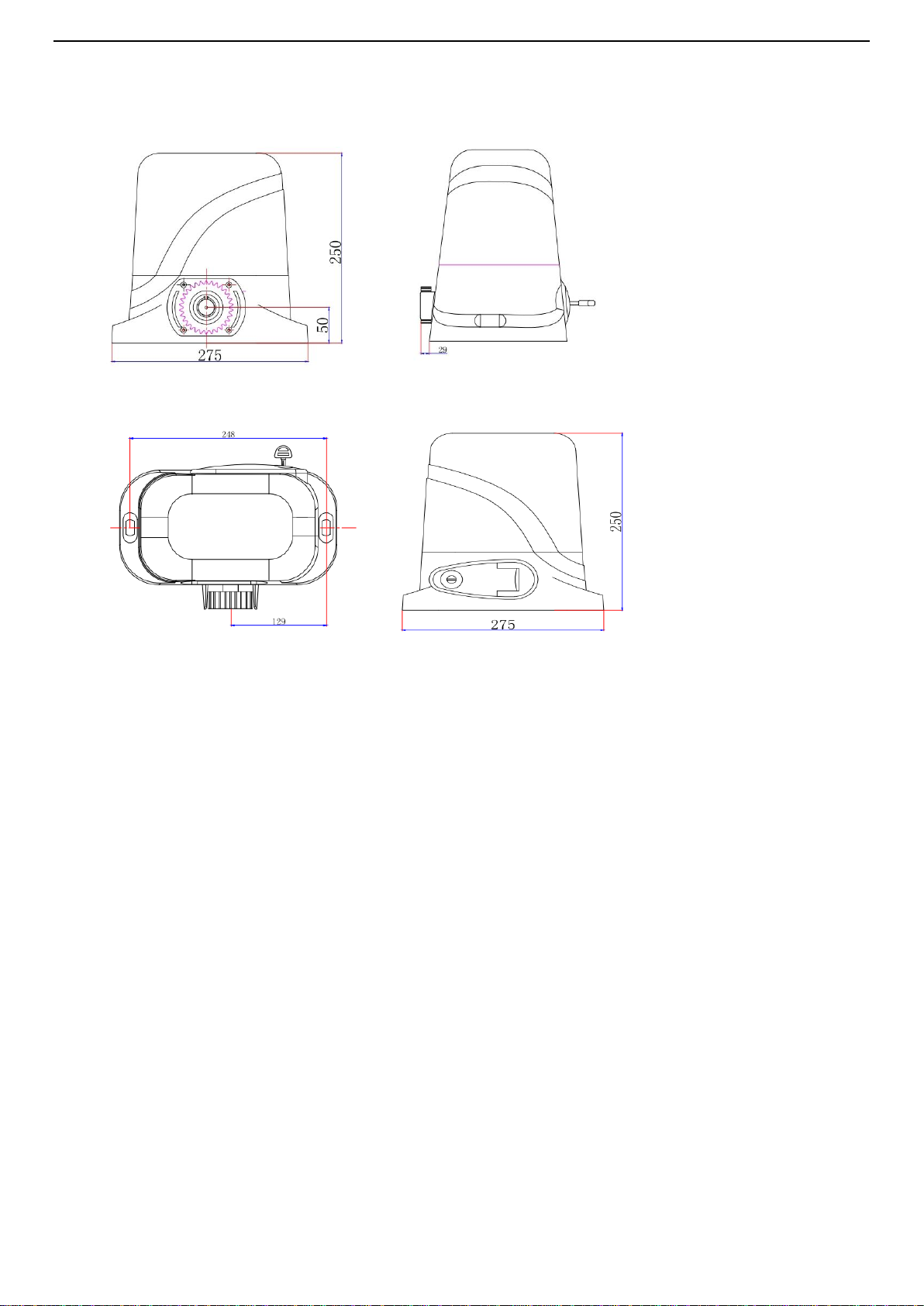
2. Appearance and dimensions

2
Fig 1
3. Parameters
1. Working temperature of motor:-25°C~+55°C
2. Working humidity:≤85%
3. Power supply:220VAC±10%/110VAC±10% 50Hz/60Hz
4. Rated power:250W
5. Output gear module:M=4
6. Output gear number:Z=16
7.Output torque:16.0 N.m
8. Open(close) speed:v=12m/min
9. Rated speed :1400RPM
10. Maximum pull:1100N
11. Maximum load:600KG
12. Net weight:10KG

3
13.Remote control distance : ≤50meter
14.Packing : In a standard carton
15. Protection Class : B
4. Features of control board
1.Stylish appearance design and built-in control panel integrated inside the mechanism,
no external controller or receiver needed.
2.Built in limit switch allowing the motor to switch off once the cycle is finished
3.Built in manual override with 2 supplied unique override keys in case of emergency or power failure.
4.The motor is constructed of all metal gears make it durable and long lasting.
5. Pedestrian mode
6. Condominium mode s
7.Resistance sensitivity and auto-closing delay time adjustable
8.Stop/Reverse in case of obstruction during gate opening and closing .
9.Easy installation, firm and solid structure, stable and reliable driving, permanently lubricated,
maintaining-free.
10.Single-phase self-lock, anti-pushing, anti-lifting ,safe and reliable.
11.Special designing for motor box which can be applier under all kinds of bad weather.
5. Installation of mechanical parts
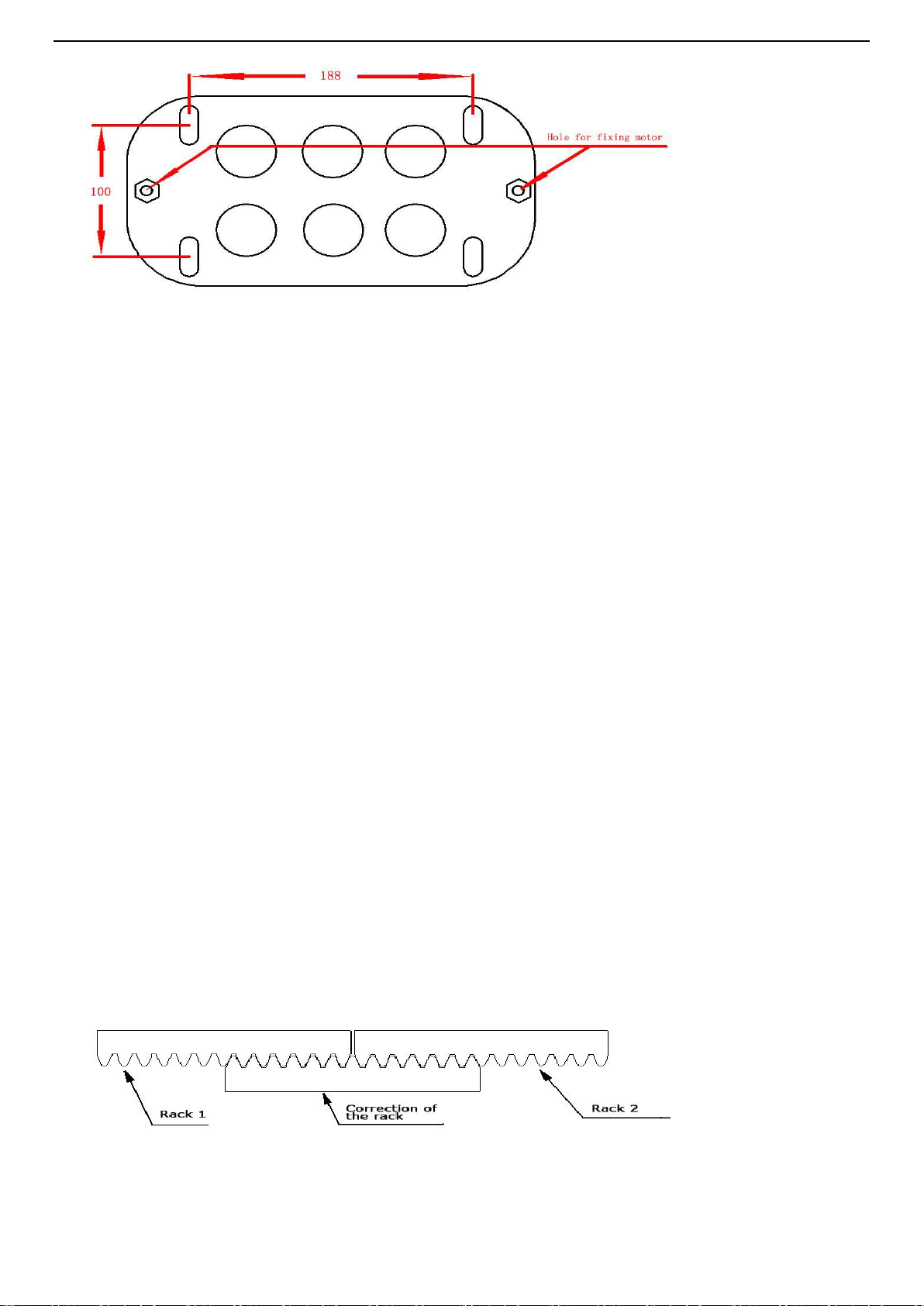
5.1 Installation of motor base plate
1. Depending on the installation size of the motor and mounting height of racks, after determine the
installation position of the motor base plate, first let the bolt embedded or use expansion bolt to make base
plate fixed on watering good cement foundation. See Fig 2
4
Fig 2
2. If the rack has been installed on the door, the motor can be fixed on the base plate. use a Allen key
rotation to the clutch "off" position, the motor and the gear rack so as to better determine the position of
the motor base plate, then remove the motor and fixed base plate.
5.2 Installation of gate opener
1.Let the sliding gate opener put on the base plate. use a random matching hexagon screw make the motor
fixed on the base plate.
2.Unscrew the screws fixed the motors cover, and then remove the motor cover. according to the electrical
wiring diagram ,connected the power cord, after adjust in good position, Then install cover and use
screws to fixed it
5.3 Installation of racks
1. After the motor is installed, the racks teeth the down ,then put the gear on the motors. and final
connected with screws and gate. push the door with hand. so can let door sliding it and can move it
without any problem .after confirmed, fixed the racks.
2. Rack is usually unit assembly, in order to avoid gate run jitter or jammed, rack and joint clearance
must be corrected. Suggest use this way, see diagram 3.with a small correction of the rack,after
connecting right with racks 1 and racks 2 ,then fixed racks 1 and 2.
Fig 3
5
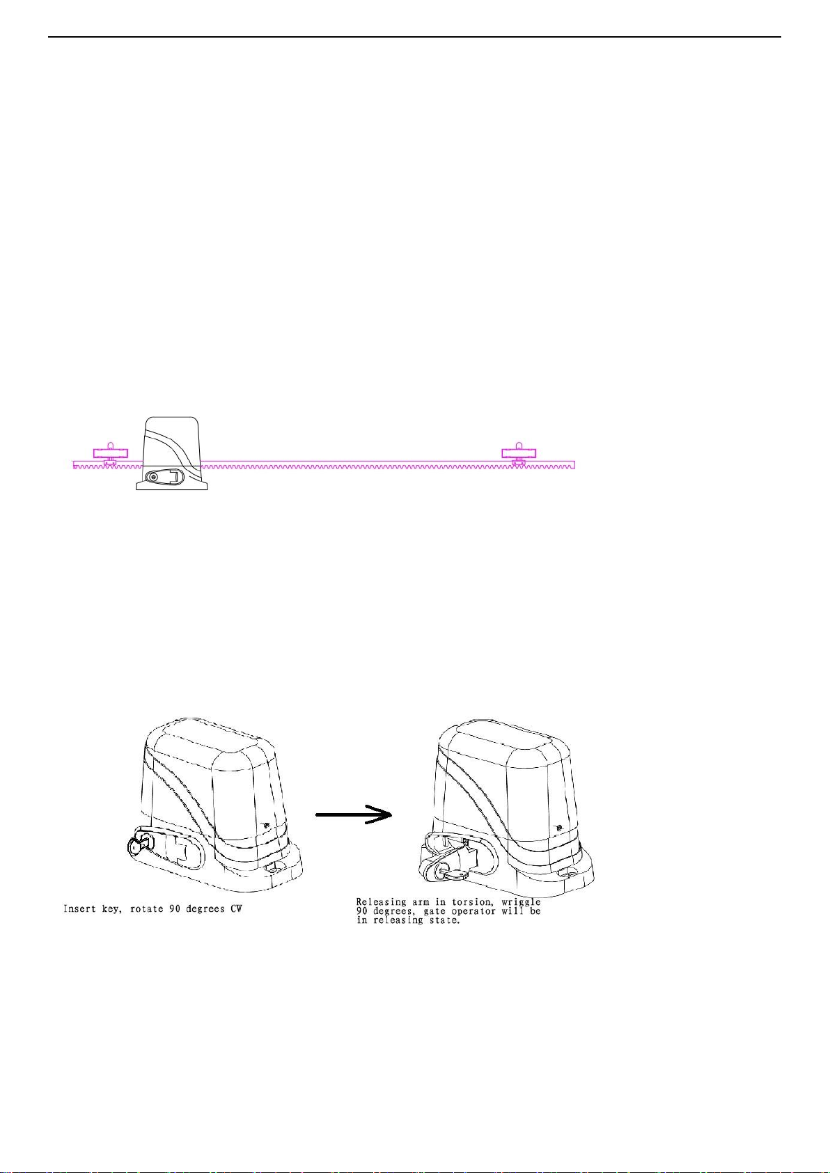
5.4 Installation of limit magnet.
There are 2 limit magnet supplied. Note there is a left hand and a right hand magnet. The magnet should
be installed one at either end of the rack. See Fig 4
To install the magnet in the correct position, open the clutch door and press the ‘CLOSE’ button on the
remote, the motor will run but will not drive the gate. Close the gate manually and adjust the limit magnet to
contact the toggle switch and switch the motor off at the desired gate position. To adjust the stop position of
the gate when it is open, press the ‘OPEN’ button, manually open the gate and adjust the other limit magnet
to contact the toggle switch and switch the motor off.
When you are satisfied the limit magnet are in the correct positions, tighten the screws in the limit
magnet to clamp them to the rack, close the clutch door and using the remote control check the gate opens
and closes to the desired positions. Adjust the limit magnet if necessary.
Fig 4
5.5 Function of clutch
When the clutch is opened to the open position, you can manually push the door; when closing the clutch,
electric door can run on, off, when touching limiting the bezel will stop automatically.
Fig 5
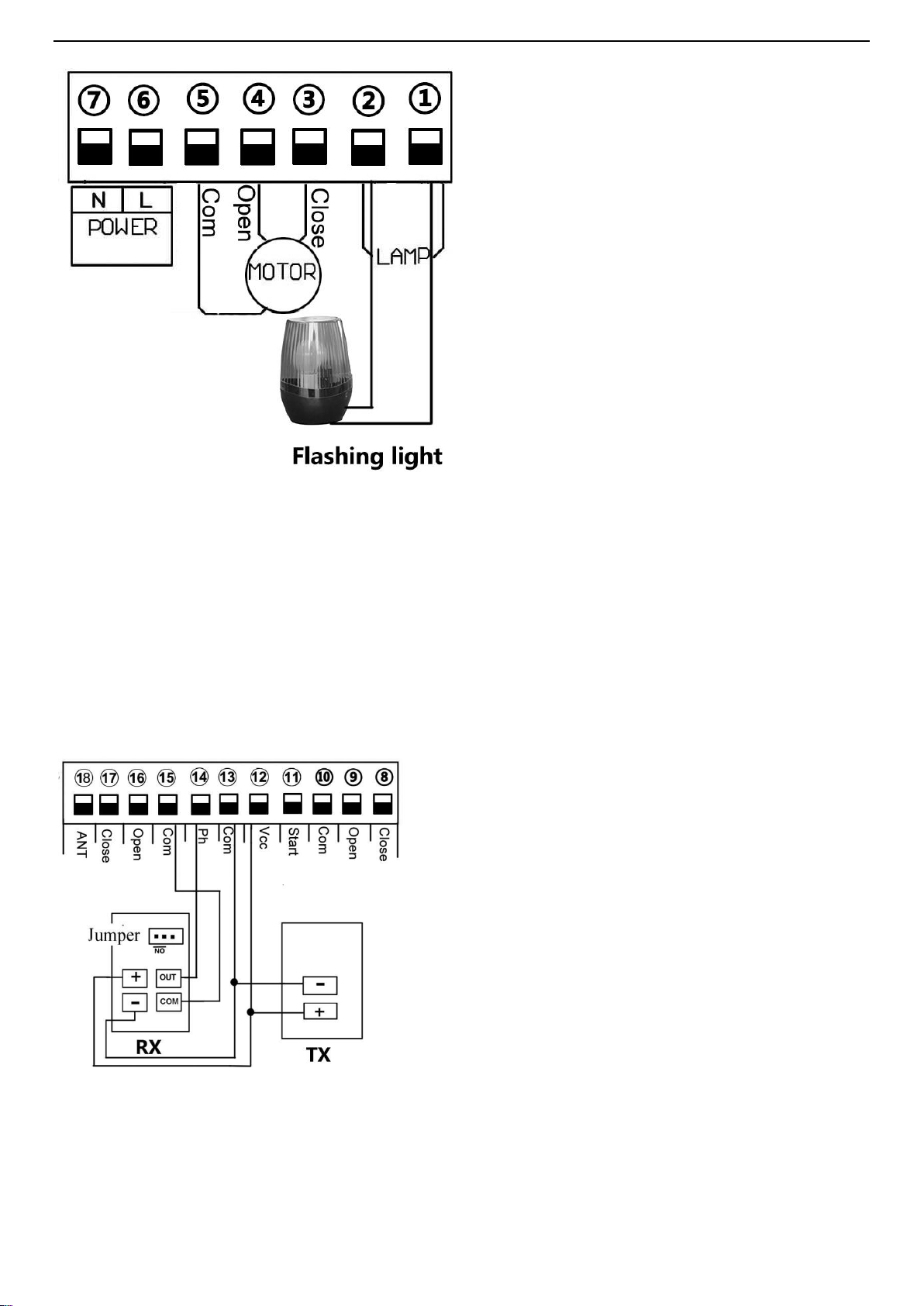
6. Installation diagram of electrical parts (Fig 6)

6
Fig 6
6.1. Terminal⑥and ⑦it for connecting to 220V power
6.2. Connect to sliding gate motor
6.2.1.Install the motor on the right of gate.(Please see Fig 7)
Fig 7
When the motor being installed to the right of gate , motor wires diagram follows
Terminal ③connect the red wire from motor. and
Terminal ④connect the yellow wire from motor.
Terminal ⑤connect the blue wire from motor.
6.2.2. Install the motor on the left of gate. (Please see Fig 8)
Please note: Our factory setting is install motor on the right of gate!

7
Fig 8
When the motor being installed to the left of gate , motor wires diagram as follows:
Terminal ③connect the yellow wire from motor. and
Terminal ④connect the red wire from motor.
Terminal ⑤connect the blue wire from motor.
6.3.Connect to flashing light. (Please see Fig 9)
Please note : When you exchange red and yellow wire, please check if the motor can close
and stop normally. If can’t ,please up or down the “J1”to the opposite direction.
Note: “J1”includes two pcs short circuit caps, you need to adjust the caps simultaneously,
then it work.
8
Fig 9
Terminal ①and ②is for flashing light .
AC220V power output, flashing light on when motor start running, after motor stop 30s, the flashing light
turn off
6.4. Terminal ⑧⑨ and ⑩is for external limit switch.
6.5. Connect to infrared sensor.(Please see Fig 10)
Fig 10
connect terminal ⑮to the “COM “of photocell RX.
connect terminal ⑭to the “OUT “of photocell RX.
Terminal is supplying power for external device.
9
So, connect terminal ⑫to the “+ “of photocell RX and TX.
connect terminal to ⑬the “-“of photocell RX and TX.
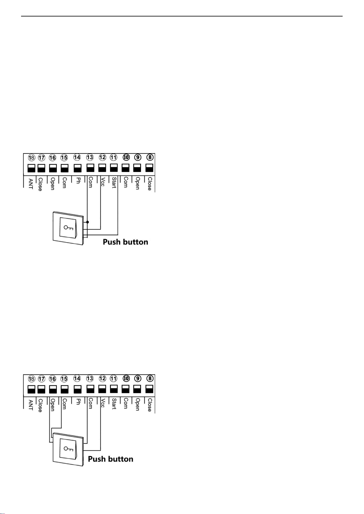
6.6.Connect to start terminal. (Please see Fig 11)
When you don’t want to use the remote control to control the gate . Terminal ⑪is for you connect some
external device , such push button, wired keypad, receiver etc.
Control gate open, stop ,close.
(Please see Fig 11)
Example for push button;
Terminal ⑪and ⑬connect to push button. Terminal ⑫and ⑬to supply power for push button
6.7.Connect to open device. (Please see Fig 12)
Terminal ⑯is open only , for external device, such push button, wired keypad, receiver etc.
Only control gate open
(Please see Fig 12)

10
Example for push button;
Terminal ⑮and ⑯connect to push button. Terminal ⑫and ⑬to supply power for push button
6.8.Connect to close device. (Please see Fig 13)
Terminal ⑰is close only , for external device such push button, wired keypad, receiver etc.
Only control gate close
(Please see Fig 13)
Example for push button;
Terminal ⑮and ⑯connect to push button. Terminal ⑫and ⑬to supply power for push button
7. Function Testing

11
Fig 14
The following functions refer to the picture Fig 14
7.1 Learn remote control code:
Remote control first button control gate open, stop, close , second button use for pedestrian mode
Code learning: Press board "LEARN" button, LED indicator light on, press remote control first button, LED
indicator flash twice, code learning succeed. If no remote control signals received within 2.6s, the
receiver will automatic quit learning functions.
Code clearing: Press and hold the button 6 seconds, LED indicator flash twice, all the code that has been
memorized in control board will be cleared
7.2 Gate open blocked detection:

12
Fig 15
As picture show, we can rotate "Open overload " potentiometer to adjust the motor open sensitivity of
blocked
A. High sensitivity : when the motor is rotation, will meet some minor resistance, then control board will
send a signal to let motor stop rotating.
B. Low sensitivity : when the motor is rotation, will meet greater resistance, then control board will send a
signal to let motor stop rotating.
C. As picture show,when pointer rotate to black part ,the control panel will quit this system
7.3 Gate close blocked detection:
Fig 16
As picture show, we can rotate "Close adjust " potentiometer to adjust the motor close sensitivity of
blocked
A. High sensitivity : when the motor is rotation, will meet some minor resistance, then control board will
send a signal to let motor stop rotating.
B. Low sensitivity : when the motor is rotation, will meet greater resistance, then control board will send a
signal to let motor stop rotating.
C. As picture show,when pointer rotate to black part ,the control panel will quit this system
8. programming setting:

13
A. Dial-up 1: Limit mode optional
OFF: NC mode(Factory setting)
ON : NO mode
Limit switch direction setting(J1):
Normal :Short circuit cap simultaneously No1 and No2 of J1 (Factory setting)
If motor system install at left of gate . Please adjust the J1 ,short the cap simultaneously No2 and No3
B. Dial-up 2: Infrared mode
OFF: NC mode(Factory setting)
ON: NO mode
If the gate meet obstacles during closing, It will auto stop and auto open. After The gate complete open to its
place, it will auto close again if the obstacle disappear within 2s, if not , it will not auto close until to the
obstacle disappear
C. Dial-up 3 &4:Auto close time setting
Auto close function activated after gate complete open to its place and stop by limit switch
Dial-up 3 &4, OFF-OFF: Auto close function disabled(Factory setting)
Dial-up 3 &4, ON-OFF: 10S
Dial-up 3 &4, ON-ON: 30S
Dial-up 3 &4, OFF-ON: 60S
D. Dial-up 5&6: Auto close time setting when pedestrian mode activated
When remote control triggers the pedestrian mode (remote control button 2 or 4), the gate will stop after
open 6s. If auto close function activated, the gate will auto close after gate open to 6s. Auto close time
setting as follows:
Dial-up 5 &6, OFF-OFF: Auto close function disabled(Factory setting)
Dial-up 5 &6, ON-OFF: 5S
Dial-up 5 &6 , ON-ON: 10S

14
Dial-up 5 &6 , OFF-ON: 30S
Note:
1.When the motor is running, the motor will stop immediately if triggers pedestrian mode
2.After triggering the pedestrian mode to open the gate for 6s, no mater it enter the countdown to close the
gate or stop status, If trigger again, the gate will close the gate immediately.
E. Dial-up 7: Condominium mode setting
OFF:Condominium mode disabled(factory setting)
ON: Condominium mode activated
When the gate is opening, trigger remote control and the start interface are invalid until the door is opened.
When the gate is closing, trigger remote control and the start interface , the gate will stop to close and auto
open until the opening limit is reached (the remote control and the start interface are invalid when the gate is
opening).
7.5 Motor Start Capacitors:
Capacitors are connected with control board before use motor, please confirmed the interface of capacitors is
secure. Please see picture Fig 14
7.6 Limited switch options (J1):
Limit switch is used to switch terminal stop detection interface, that direction of open and close the gate
7.7 Terminal stop detection interface:
Terminal for limit switch, such as spring limit or magnetic limit .
7.8 Power switch:
Switch on /off power stop when do some setting on the control board

15
8.Trouble Shooting
Problem
Possible causes
Repair method
Gate fails to
operate
1. Check the clutch states ,power-driven state or not ?
2. Power no indication, and power trip.
3. The fuse has broken
4. Remote control failure or invalid
5. Damaged power cable
6. Remote control or motor problem
Recovery
To restore power
Change the fuse
Detection or change
Detection and Repair
Detection and Repair
Working distance
of remote control
reduced
1. Low battery power or damaged
2. Interference from equipment using the same
frequency
3. The receiver of controller was damaged
Replace battery
Wait eliminate interference
Replace the control board
Gate fails to stop
at start or end
position
1.The terminal stop toggle switch is damaged or
obstructed.
2. Limit switch of the motor and the limit detection
of the interface PCB board plug off.
3. Limit of open and close is in wrong position.
Replace toggle switch or
remove obstruction
Insert and fixed it
Adjust of limit switch(K1)
Press open and
close key of
motor, but cant
working and
operate
1. Blocked sensitivity is too high(set too big)
2. The gate has lifted off the track and disengaged
the drive gear from the rack
Make blocked sensitivity
lowered ,and check gear and
racks can operate normally.
Maintenance and replace.
8.Trouble Shooting
1. When someone or obstructions between the gate, do not open or close the door to ensure safety.
2. The power supply for the control board should be equipped with a separate switch
with a fuse rated at 10AMP.

16
3. There is strong electricity in the control box. Please cut off the power supply before opening the cover.
4. Motor gear modulus M = 4, number of teeth = 16, use the corresponding racks
5. the gate should be as straight as possible, making sure after racks fixed good and the gate can be in a good
position with motor gear.
6. Racks and gear should be controlled in good gap. so can make sliding steady.
7. After confirm the direction of gate movement . please check if the limit block fixed in good position to
avoid the motor run out of control due to failure

17
Зміст
1. Резюме········································(17)
2. Зовнішній вигляд і розміри ······················(18)
3. Характеристики·································(18)
4. Особливості ····································(2)
5. Встановлення механічних частин···················(2)
5.1 Встановлення опорної пластини··················(2)
5.2 Встановлення двигуна··························(3)
5.3 Встановлення рейки····························(3)
5.4 Встановлення магнітних кінцевиків···············(3)
5.5 Ручний розблоковувач··························(4)
6. Схема монтажу електричних деталей·················(4)
7.Налаштування····································(8)
8.Вирішення проблем·······························(11)
9.Важливі примітки································· (11)
1. Резюме
Ця автоматика є однією з автоматик для відкатних воріт, випущених нашою компанією, з новою
конструкцією і інтегрованою системою управління. Наша нова автоматика має безліч характеристик,
таких як: низький рівень шуму, мала вага, високий пусковий момент, стабільність, надійність,
компактність і стильність. Двигун деякий час може працювати на низькій напрузі. Плата управління
має захист від перевантаження. Коли відбувається збій живлення, привід може бути розблокований за
допомогою ручного розблоковувача. Доданим ключем користувач може відключити муфту, і
відкривати або закривати ворота вручну. Використовуючи додаткові інфрачервоні фотоелементи,
ворота автоматично зупиняться і знову відкриються, якщо виявлена перешкода.
18
2. Зовнішній вигляд і розміри
Рис 1
3. Характеристики
1. Робоча температура:-25°C~+55°C
2. Робоча вологість:≤85%
3. Живлення: 220 В змінного струму ± 10% / 110 В змінного струму ± 10% 50 Гц / 60 Гц 4. Rated
power:250W
5. Модуль вихідної передачі: M = 4
6. Номер вихідної передачі: Z = 16
7. Вихідний крутний момент: 16,0 Нм
8. Швидкість відкриття (закриття): v = 12м / хв
9. Номінальна швидкість: 1400 об / хв
10. Максимальна тяга: 1100Н
11. Максимальне навантаження: 600 кг

19
12. Вага нетто: 10 кг
13. Відстань дистанційного управління: ≤50 метрів
14. Упаковка: Кортонна коробка
15. Клас захисту: B
4. Особливості
1. Стильний зовнішній вигляд, панель управління, вбудована всередину механізму, не потрібен
зовнішній контролер або приймач.
2. Вбудований кінцевий вимикач, що вимикає двигун після закінчення циклу
3. Ручний розблоковувач з 2 унікальними ключами, що входять до комплекту, у випадку надзвичайної
ситуації або відключення електроживлення.
4. Усі шестерні в двигуні металічні, що робить його міцним і довговічним.
5. Режим «Хвіртка»
6. Режим кондомініуму S
7. Чутливість до опору та час затримки автоматичного закриття регулюються
8. Зупинка / реверс у разі перешкоди під час відкривання та закривання воріт.
9. Простий монтаж, міцна та надійна конструкція, стабільний та надійний хід,
10.Однофазний, безпечний та надійний.
11.Спеціальне проектування корпусу, що може застосовуватися при будь якій погоді.
5. Встановлення механічних частин
5.1 Встановлення опорної пластини двигуна
1. Залежно від монтажного розміру двигуна та висоти кріплення зубчастої рейки, після визначення
монтажного положення опорної пластини двигуна спочатку вмонтуйте болти або за допомогою
дюбелів закріпіть фундаментну пластину на бетонному фундаменті. Див. Рис. 2
Table of contents
Languages:
Other STEELON Gate Opener manuals

Popular Gate Opener manuals by other brands


Nice
Nice MFAB3000 Instructions and warnings for installation and use

tousek
tousek SWING 225 AEB/29 N Installation and operating manual

Viper
Viper TR-3 Installation and owner's manual

Merlin
Merlin Swing L 300 MGL Series Installation and operating instructions

Novoferm
Novoferm Vetrata NOVOFIRE Mounting instructions

CAME
CAME Ferni Series Manaul


