STEIN Radius Circuit 90 User manual

STEIN300_Radius Circuit_06_GB.doc / 01.2020 1
Radius Circuit 90 °
Radius Circuit 180 °
STEIN Workpiece Transport System
Operating instructions
Attention all installation, operating and maintenance personnel -
always keep these instructions by the radius circuit!

2 STEIN300_Radius Circuit_06_GB.doc / 01.2020
©by STEIN
Automation
The copyright for these documents is reserved by STEIN Automation.
These documents may not be altered, distributed, reproduced or transferred to third par-
ties without the prior written permission of STEIN Automation.
STEIN
Automation GmbH & Co. KG
Carl-Haag-Straße 26
78054 VS-Schwenningen, Germany
Telephone: (+)49 (0)7720 / 8307 – 0
Publication date: January 2020
The right to make changes in design and construction is reserved.

STEIN300_Radius Circuit_06_GB.doc / 01.2020 3
Contents
1Abbreviations and symbols ............................................................................................................................4
1.1 Explanation of safety and warning notices .......................................................................................... 4
2Introduction ......................................................................................................................................................5
2.1 Short description................................................................................................................................ 6
2.2 Initial inspection................................................................................................................................. 7
2.3 Complaints......................................................................................................................................... 7
2.4 Warranty ............................................................................................................................................ 7
3Safety instructions...........................................................................................................................................8
3.1 General safety information ................................................................................................................. 8
3.2 Appropriate use and liability exclusions .............................................................................................. 8
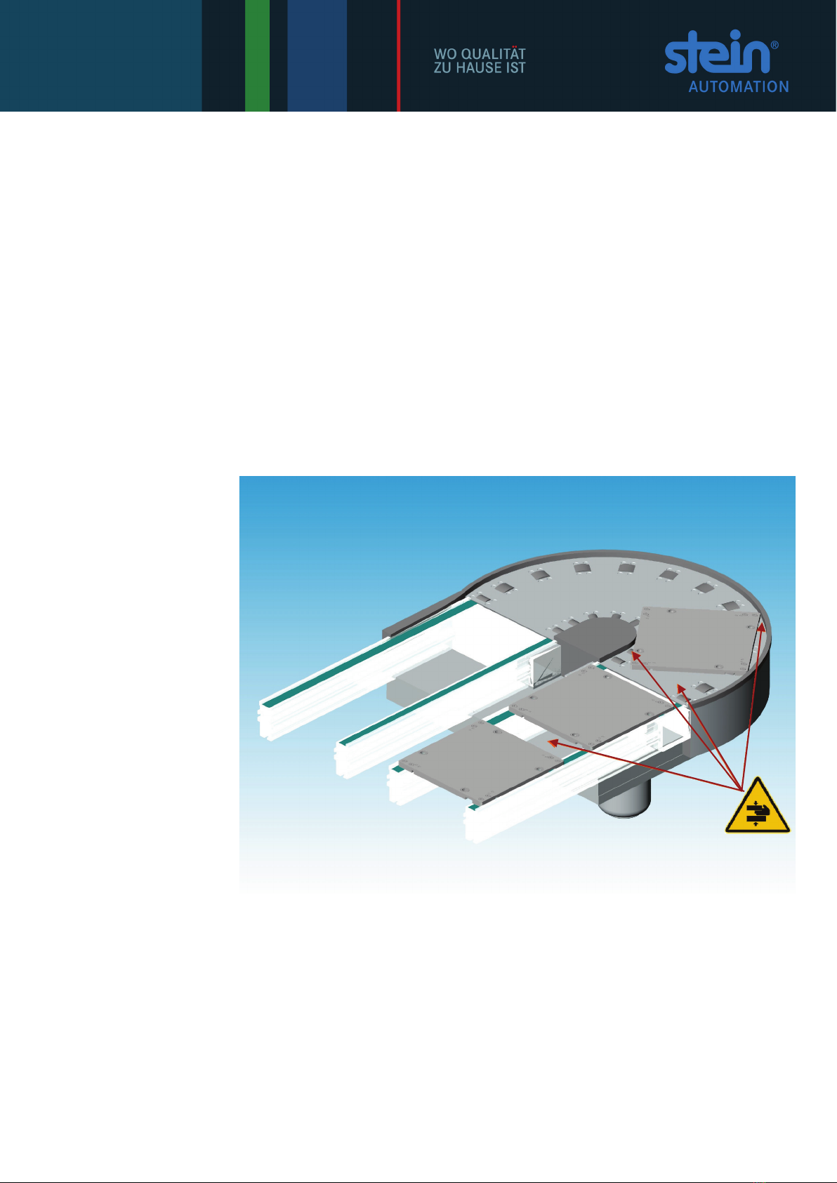
3.3 Residual danger ................................................................................................................................. 9
3.4 Safety information for installation and repair work............................................................................ 10
4Technical description ................................................................................................................................... 11
4.1 Scope of delivery.............................................................................................................................. 11
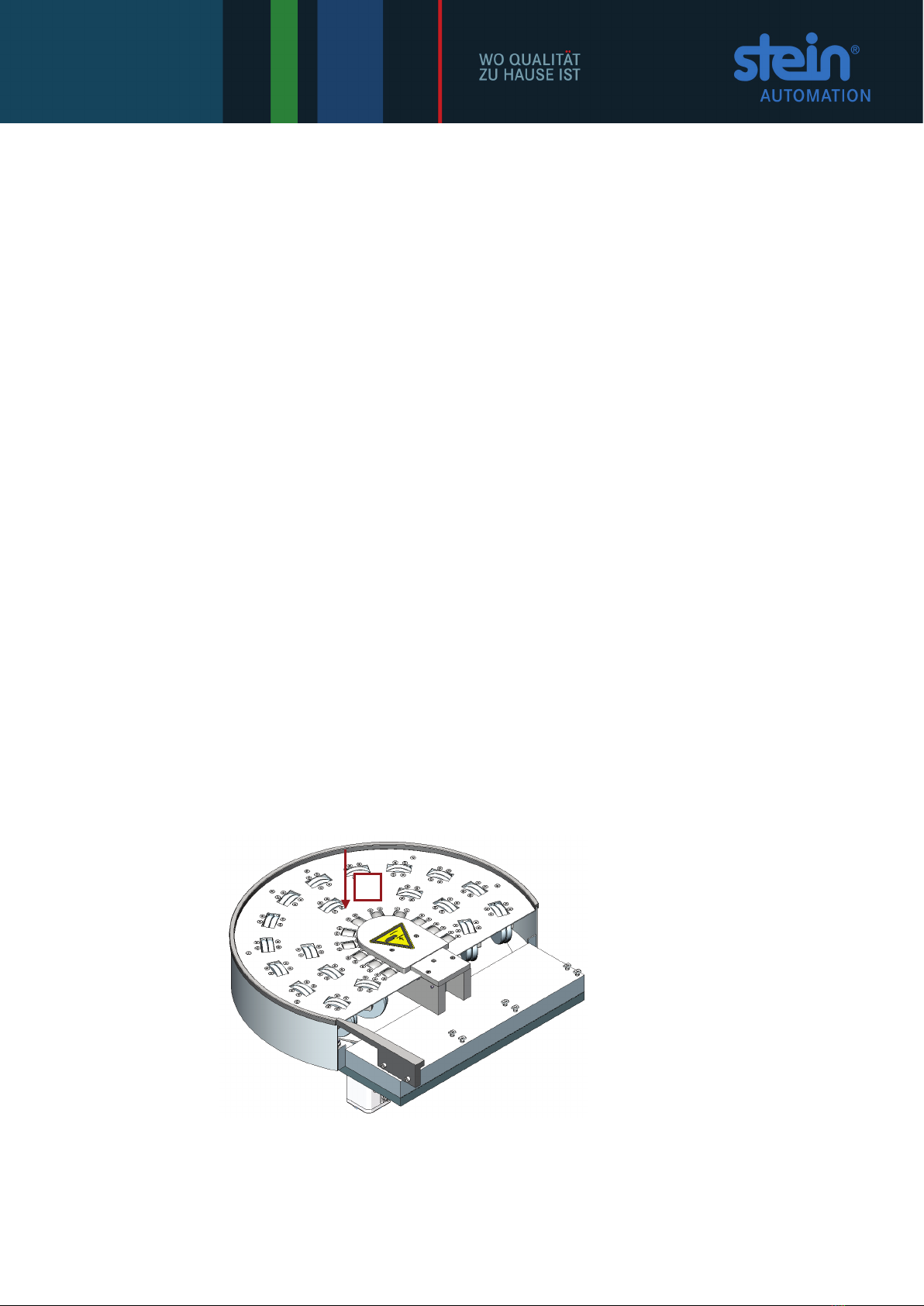
4.2 WT orientation.................................................................................................................................. 12
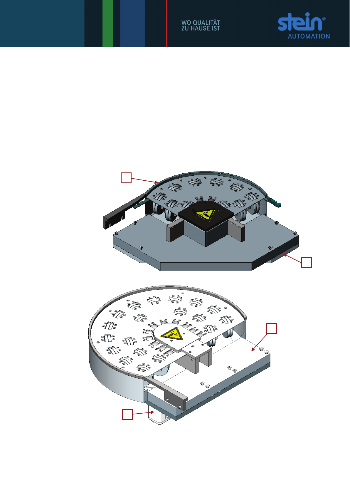
4.3 Sub-assemblies ................................................................................................................................ 12
5Radius circuit installation ............................................................................................................................ 13
5.1 Procedure ........................................................................................................................................ 13
5.2 Preparation ...................................................................................................................................... 13
5.3 Radius circuit installation and de-installation .................................................................................... 14
5.4 Connection of the radius circuit to the mains supply ........................................................................ 17
5.5 Pile-up separator installation ............................................................................................................ 17
6Initial operation ............................................................................................................................................. 18
7Radius circuit operation ............................................................................................................................... 19
8Faults.............................................................................................................................................................. 20
8.1 Causes of faults and troubleshooting problems ................................................................................ 20
9Cleaning, inspection, maintenance............................................................................................................. 21
9.1 Cleaning........................................................................................................................................... 21
9.2 Inspection ........................................................................................................................................ 22
9.3 Maintenance .................................................................................................................................... 22
10 Dimensions sheet.......................................................................................................................................... 23
11 Spare parts..................................................................................................................................................... 24
11.1 300 095 001 Radius circuit 90° - PB 160x160 ................................................................................. 24
11.2 300 093 001 Radius circuit 90° - PB 240x240 ................................................................................. 27
11.3 300 151 001 Radius circuit 90° - PB 320x320 ................................................................................. 30
11.4 300 102 001 Radius circuit 90° - PB 400x400 ................................................................................. 33
11.5 300 089 001 Radius circuit 180° - PB 160x160............................................................................... 36
11.6 300 104 001 Radius circuit 180° - PB 240x240............................................................................... 39
11.7 300 098 001 Radius circuit 180° - PB 320x320............................................................................... 42
11.8 300 096 001 Radius circuit 180° - PB 400x400............................................................................... 45
11.9 300 789 001 Stand for radius circuit STRB....................................................................................... 48
11.10 300 790 001 Double column stand for radius circuit DSTRB ............................................................ 49
11.11 930 001 001 F1 Stand for radius circuit RBF1.................................................................................. 50
11.12 930 002 001 F2 Stand for radius circuit RBF2.................................................................................. 51

4 STEIN300_Radius Circuit_06_GB.doc / 01.2020
11.13 930 003 001 F1 Double column for radius circuit RBDF1................................................................. 52
11.14 930 004 001 F2 Double column for radius circuit RBDF2................................................................. 53
12 Accessories .................................................................................................................................................... 54
12.1 Drive motors – Mounting kit ............................................................................................................. 54
13 Appendix.........................................................................................................................................................60
13.1 Technical data.................................................................................................................................. 60
1Abbreviations and symbols
Action symbol
1 Symbol for actions which must be carried out in a specified sequence.
⇒Consequence or result of an action
•Count
RB90 Radius circuit 90°
RB180 Radius circuit 180°
BA Operating instructions
WT Pallet
BE Belt element
Fig. Figure
i This sign indicates information that will allow the radius circuits to be used more effec-
tively and more economically.
The symbols used in the operating instructions for safety and hazard warnings are de-
scribed in detail in chapter 3.
1.1 Explanation of safety and warning notices
The following safety signs explain all the situations or actions where danger to life and
limb for machine operators or their colleagues exists.
Strictly comply with these instructions and act with particular care in these cases. Pass
all safety notices on to all other users.
DANGER!
The symbol with the added designation DANGER describes a directly impending
hazards!
The hazard results in serious injury to people or even fatalities.
WARNING!
The symbol with the added designation WARNING describes a potentially
impending hazards!
The hazard may result in serious injury to people or even fatalities.
CAUTION!
The symbol with the added designation CAUTION describes a potentially
hazardous situation!
The hazard can result in injury to people.

STEIN300_Radius Circuit_06_GB.doc / 01.2020 5
he safety signs appear frequently in the text with a picture to explain what the source of
the hazard is.
CRUSHING HAZARD!
This symbol gives warning of a location where there is a risk of being crushed.
HIGH ELECTRICAL VOLTAGE!
This symbol gives warning of possible electric shock.
It appears for all working and operating procedures that must be followed precisely, in
order to avoid injury to personnel or damage to the system through high electrical volt-
age.
Other warning signs:
ATTENTION!
This symbol indicates warnings which, if ignored, will cause a hazard to the machine.
Protective clothing must be worn!
Wear your personal safety clothing:
Safety footwear, hard hat, goggles and safety gloves.
Environmental protection!
This sign indicates warnings that will help to avoid harming the environment.
2Introduction
The safety of all persons who come into contact with the radius circuit depends funda-
mentally on knowing how the device functions. Therefore:
Read these operating instructions before using the unit for the first time.
These operating instructions contain important information which will ensure the correct,
economical and safe operation of your radius circuit.
i If not specifically mentioned as deviating, then the same information applies to the radius
circuits that are not described in detail as for the radius circuits described below.

6 STEIN300_Radius Circuit_06_GB.doc / 01.2020
2.1 Short description
Radius circuits are installed in the STEIN 300 Workpiece Transport System. The radius
circuit changes the transport direction of the pallet.
In conjunction with the Workpiece Transport System, the radius circuit provides:
•a change in the WT transport direction
•keeping the WT orientation despite a change in direction.
The radius circuit 180° consists of:
Fig. 4-1:
Radius circuit 180°
- components
1 Guide track
2 Base plate
3 Drive motor
4 Housing
1
2
3
4

STEIN300_Radius Circuit_06_GB.doc / 01.2020 7
2.2 Initial inspection
The radius circuit is delivered either pre-assembled as a module or separately.
If delivered separately, the radius circuit is securely transported in a solid box.
Unpack all the components supplied.
Environmental protection!
Dispose of all packaging material in an environmentally responsible way.
Then carry out an initial inspection.
Check that:
all components detailed on the delivery note have been supplied
components have not been damaged or lost in transit.
2.3 Complaints
In order for claims for damage caused in transit to be accepted, follow this procedure:
Inform the freight company.
Draw up a damage report giving the following details
•Name and address of recipient
•Item or order number
•A description of the damage.
Send components, if possible in their original packaging, with the damage report,
back to the manufactures.
2.4 Warranty
For the radius circuit and its spare parts we grant the legal guarantee period or rather
the defined guarantee period in the contract, starting with the day of delivery.
During this warranty period we will replace any components defective in manufacture or
materials free of charge.
STEIN Automation's general warranty and guarantee conditions also apply.

8 STEIN300_Radius Circuit_06_GB.doc / 01.2020
3Safety instructions
3.1 General safety information
Radius circuits from STEIN Automation
are high quality products, manufactured to
recognised technical specifications.
The radius circuit left the manufacturing plant in a perfectly safe technical condi-
tion.
All models of the radius circuit comply with the requirements of UVV, the German
accident prevention regulations.
To maintain this situation, installation staff, users and service technicians must ob-
serve the notices and warnings contained in these operating instructions.
Radius circuits must only be installed and repaired by authorised personnel who
have been trained by STEIN Automation.
Only genuine spare parts from STEIN Automation may be used when carrying out
repairs to the radius circuit.
3.2 Appropriate use and liability exclusions
The radius circuit must only
be built into STEIN 300 belt systems.
Compatibility is only assured with STEIN 300 belt modules.
Be operated with suitable pallets with the permitted dimensions and weights
Be used indoors
Be operated in dry areas
Be employed in areas where there is no risk of explosion
Be used in a non-congested operation.
Fig. 3-1:
Radius circuit
- Maximum loading
Permitted loading is:
•In the Z-axis: 12 Kg (WT + workpiece)
•
Z

STEIN300_Radius Circuit_06_GB.doc / 01.2020 9
i Unauthorised interventions, alterations or repairs carried out on the radius circuit
invalidate the guarantee.
STEIN Automation accepts no liability for damage caused by unauthorised
interventions, changes or repairs!
3.3 Residual danger
Radius circuits are manufactured using state-of-the-art technology and to recognised
safety standards Despite that, their use can lead to dangerous situations for users or
third parties arising or to impairments of the system and other material assets.
If used improperly, amongst others, the following injuries can result:
•Crushing:
- by getting caught between the WTs
- by getting caught between the WT and guide track or guide rails.
Fig. 3-2:
Potential crushing points

10 STEIN300_Radius Circuit_06_GB.doc / 01.2020
3.4 Safety information for installation and repair work
DANGER!
In the area of the radius circuit due to an unexpected start up!
DANGER!
HIGH ELECTRICAL VOLTAGE!
Risk of electric shock!
1 Before carrying out any installation or repair work, disconnect the relevant radius
circuit from its electrical power supply.
2 Put up warning signs to prevent the system being started up while installation and
repair work is being done.
3 Remove all pallets from the affected radius circuit.
4 Carry out the work
•in accordance with the descriptions in this documentation,
•complying with relevant safety and accident prevention regulations and
•in a technically correct manner and with the greatest possible accuracy.
5 After completing installation or repair work, carry out a test run of the entire sys-
tem and check that all safety features are functioning correctly.
DANGER!
Never operate the radius circuit using
•defective safety equipment and / or
•damaged components.

STEIN300_Radius Circuit_06_GB.doc / 01.2020 11
4Technical description
4.1 Scope of delivery
Radius circuits 90° and 180° are delivered:
•With drive motor and
•Entry and exit transfers (fitted to the BE).
i The following accessories are not part of the normal scope of delivery:
•Control unit (STEIN Automation option)
•Safety cover over the drive rollers (STEIN Automation optional extra)
i Pile-up separation is achieved by the installation of P-accessories (STEIN Automation
optional extra).
Fig. 4-1:
Basic configurations:
1 E-basic configuration
with 180° radius cir-
cuits
2 F-basic configuration
with 90° radius cir-
cuits
E-basic configurations (WTS- Alpha) are equipped with 180° radius circuits.
F-basic configurations are equipped with 90° radius circuits.
i
The distance between the belt elements in the case of the E-basic configuration (inside
width) is 106 mm.
Radius circuit 90°
The 90° radius circuit changes the transport direction of the WT through 90°. The 90°
radius circuit is fitted to the guide profiles of the belt element.
Radius circuit 180°
The 180° radius circuit guides the WT onto a parallel-running section.
Procedure:
The WT is transported up to the entry point of the radius circuit by the two transport
belts of the belt element. Then the WT direction is changed by 90° or 180° respectively
through it being transported on over the roller section of the radius circuit. At the exit
point of the radius circuit, a belt element takes over the onward transport of the WT.
i Standard WTS sizes: 160x160, 240x240, 320x320, 400x400 mm
Other sizes on request.
1
2

12 STEIN300_Radius Circuit_06_GB.doc / 01.2020
4.2 WT orientation
Fig. 4-2:
Radius circuit 180° with
pallet
i The outside of the workpiece remains on the outside after the 180° change of direction.
i Please note:
The orientation of the WT remains the same!
4.3 Sub-assemblies
The radius circuit 180° consists of:
Fig. 4-3:
Radius circuit 180°
- components
1 Base plate
2 Housing
3 Roller section
4 Guide track
5 Guide rail
6 Rotating plate
7 Drive motor
i To install a radius circuit machined belt elements with guide rails are required.
5
4
3
2
1
6
7

STEIN300_Radius Circuit_06_GB.doc / 01.2020 13
5Radius circuit installation
i As a rule, the radius circuit is delivered complete with fitted belt elements.
For more information regarding the installation of the Workpiece Transport System,
please refer to the STEIN 300 NT operating manual, chapter 5.
5.1 Procedure
The installation procedure can be divided into 5 phases:
Preparation,
Radius circuit de-installation,
Radius circuit installation,
Connection of the radius circuit to the mains supply,
Installation of the pile-up separator.
WARNING!
On processing stations which generate shavings (for example drilling or
thread-cutting machinery), covers should be installed to avoid shavings or
cooling fluid coming into contact with the radius circuit or the drive motor.
i
Further information is available from STEIN Automation.
5.2 Preparation
DANGER!
From the Workpiece Transport System starting unexpectedly.
DANGER!
HIGH ELECTRICAL VOLTAGE!
Risk of electric shock!
i The following information describes repair action to the radius circuit and not the initial
installation.
1 Before carrying out any installation or repair work, disconnect the relevant Work-
piece Transport System from its electrical power supply.
2 Put up warning signs to prevent the system being started up while installation and
repair work is being done.

14 STEIN300_Radius Circuit_06_GB.doc / 01.2020
5.3 Radius circuit installation and de-installation
i For the replacement of the radius circuit if it is defective or conversions where it is re-
moved.
Protective clothing must be worn!
Wear your personal safety clothing: Safety footwear and safety gloves.
WARNING!
Remember that the radius circuit is very heavy!
Use suitable equipment, such as a fork-lift truck, to transport and install the radius cir-
cuit.
De-installation
Fig. 5-1:
Example:
180° radius circuit seen
from below
1 Belt element
2 Base plate
3 Module connecting
screws
4 Stand connecting
screws
i In the following section the radius circuit and stand base assembly are together called
module.
Place a protective mat the size of the radius circuit onto the floor.
This avoids the radius circuit getting damaged.
Fit support sections to the relevant belt element so that it is held up once the module
has been removed.
Unscrew the connecting screws in the belt element (3).
Remove the module from the belt element with the aid of suitable lifting gear or
through help from assistants.
Place the module onto the protective mat so that the underneath of the radius circuit
is on top.
Unscrew the stand connecting screws (4).
1
2
3
4

STEIN300_Radius Circuit_06_GB.doc / 01.2020 15
Fig. 5-2:
Example:
Radius circuit 180°
Radius circuit 90°
1 Double column stand
2 Single column stand
3 Adjustable bases
180° radius circuit: Remove the double column stand from the radius circuit
90° radius circuit: Remove the two stands from the radius circuit.
Installation
Place the radius circuit onto the protective mat so that the underneath of the radius
circuit is on top.
180° radius circuit: Attach the double column stand to the radius circuit.
90° radius circuit: Attach the two stands to the radius circuit.
Tighten the stand connecting screws.
Fig. 5-3:
Adjustable base adjust-
ment
1 Locknut
2 Adjustable base
Adjust the stand bases to their lowest level.
Erect the module into a vertical position with the aid of suitable lifting gear or
through help from assistants.
1
3
2
3
1
2

16 STEIN300_Radius Circuit_06_GB.doc / 01.2020
Fig. 5-4:
Example:
180° radius circuit seen
from below
1 Belt element
2 Base plate
3 Reversing switch
Attach the base plate of the radius circuit to the belt element.
Remove the support sections that were previously fitted to the relevant belt element.
Fig. 5-5:
Example:
180° radius circuit
X/Y/Z alignment
Align the module in the Z-direction. The transport belt of the belt element and the
transport rollers of the radius circuit must be aligned horizontally to one another.
1
2
3
X
Y
Z

STEIN300_Radius Circuit_06_GB.doc / 01.2020 17
WARNING!
Do not unscrew the adjustable bases (2) of the module too far out!
The threading has to remain firmly within the stand.
Make sure that there is still sufficient thread available to allow for adjustments that
may need to be made after setting up the other modules, to allow for unevenness in
the floor.
Align the radius circuit in the X- and Y-directions.
Turn the adjustable bases with an open-jaw spanner
•until the module is aligned horizontally in the X- and Y-directions and
•the junction of the belt element and radius circuit is at the same level and
•the module stands firmly on the floor on all its feet.
After this adjustment process, screw all the stand base locknuts on the first module
tight.
i Please refer to chapter 10 for the installation and other dimensions.
5.4 Connection of the radius circuit to the mains supply
DANGER!
Connection to the mains power supply must be carried out exclusively by trained
specialists from STEIN Automation!
WARNING!
Be sure to use only approved plug-and-socked systems when connecting to the
power supply.
i
Further information can be found in the technical description of the
“STEIN 300 Drive Motors”.
5.5 Pile-up separator installation
i Further information can be found in the technical description of the “Stopping Device”
(SE).
Also see the service video “Stopper replacement”.

18 STEIN300_Radius Circuit_06_GB.doc / 01.2020
6Initial operation
Carry out the following checks before initial operation:
Are all the electrical cables undamaged?
Have all the mechanical components been tightly fastened in place?
Have all tools and other equipment been cleared from the transport area?
Has all the safety equipment been installed?
Once you have carried out all these checks, you can continue with the initial operation.
Switch on the Transport System and its associated processing stations and carry out
a trial run.
Check the functions of the individual elements and processing stations as well as the
pre-programmed overall operation of the entire system.
Check the direction of movement of the radius circuit.
i It can happen that during idle running (without any WT on the radius circuit) individual
rollers are not driven. This is not a fault but only a situation related to the construction.
WARNING!
Only start the Transport System once you have carried out a successful trial run.

STEIN300_Radius Circuit_06_GB.doc / 01.2020 19
7Radius circuit operation
Fig. 7-1:
Radius circuit 90° and
Radius circuit 180°
In normal operation the radius circuit is controlled by the WTS control system.
•The WT is transported by the belt element to the entry point of the radius circuit
•After entering the radius circuit the WT is turned through either 90° or 180°
•At the exit point of the radius circuit, a belt element takes over the onward transport
of the WT.
i Please note:
The orientation of the WT is not changed by the radius circuits!
See page 12, fig. 4.2.
ATTENTION!
The motor must be operated in continuous operation, or velocity must be reduced
via a brake ramp when turning off the motor.
Abrupt turn off of the motor, can damage the radius circuit (rotating plate)!

20 STEIN300_Radius Circuit_06_GB.doc / 01.2020
8Faults
WARNING!
It is not permitted to repair damaged and / or defective parts.
Get in touch with STEIN Automation.
The service address is on page 2.
8.1 Causes of faults and troubleshooting problems
Faults Cause Solution
The radius circuit motor is not work-
ing
•Motor not connected to the
power supply
•Plug connection wiring wrong
•Possibly plug connection wiring
of extension cable wrong
Connect module power supply
cables (properly)
Correct the plug connection
wiring (must be done by a
qualified electrician)
Correct the plug connection
wiring of the extension cable
(must be done by a qualified
electrician)
Radius circuit motor runs in the
wrong direction
•Reversing switch in the wrong
position
•Plug connection wiring wrong
•Possibly plug connection wiring
of extension cable wrong
Correct the reversing switch
position
This manual suits for next models
1
Table of contents
Other STEIN Industrial Equipment manuals
Popular Industrial Equipment manuals by other brands

Raycus
Raycus RFL-C8000S-CE user guide

Sealey
Sealey ADT7 instruction manual

Eaton
Eaton P1/Z Plus SVB Series Instruction leaflet

Stearns
Stearns 1-056-700 Series Installation and service instructions

Festool
Festool VAC SYS VP Original operating instructions/Spare parts list

Jäger
Jäger Z45-D145.04 S15A manual