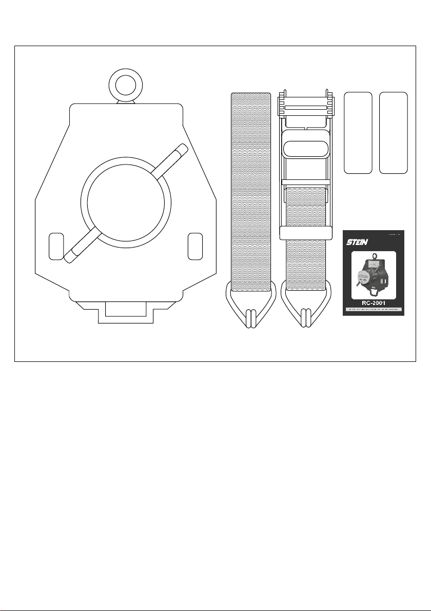
RC Instruction Manual
2
WARNING
Activities using this type of equipment are inherently dangerous. It is not possible to cover every eventuality
relating to the use of this equipment. Purchasers and users of RC devices should seek professional training from
a fully qualified and competent instructor prior to engaging in any activity. If you are not able, or not in a position
to assume this responsibility, do not use this product. The manufacturer its distributors and retailers do not
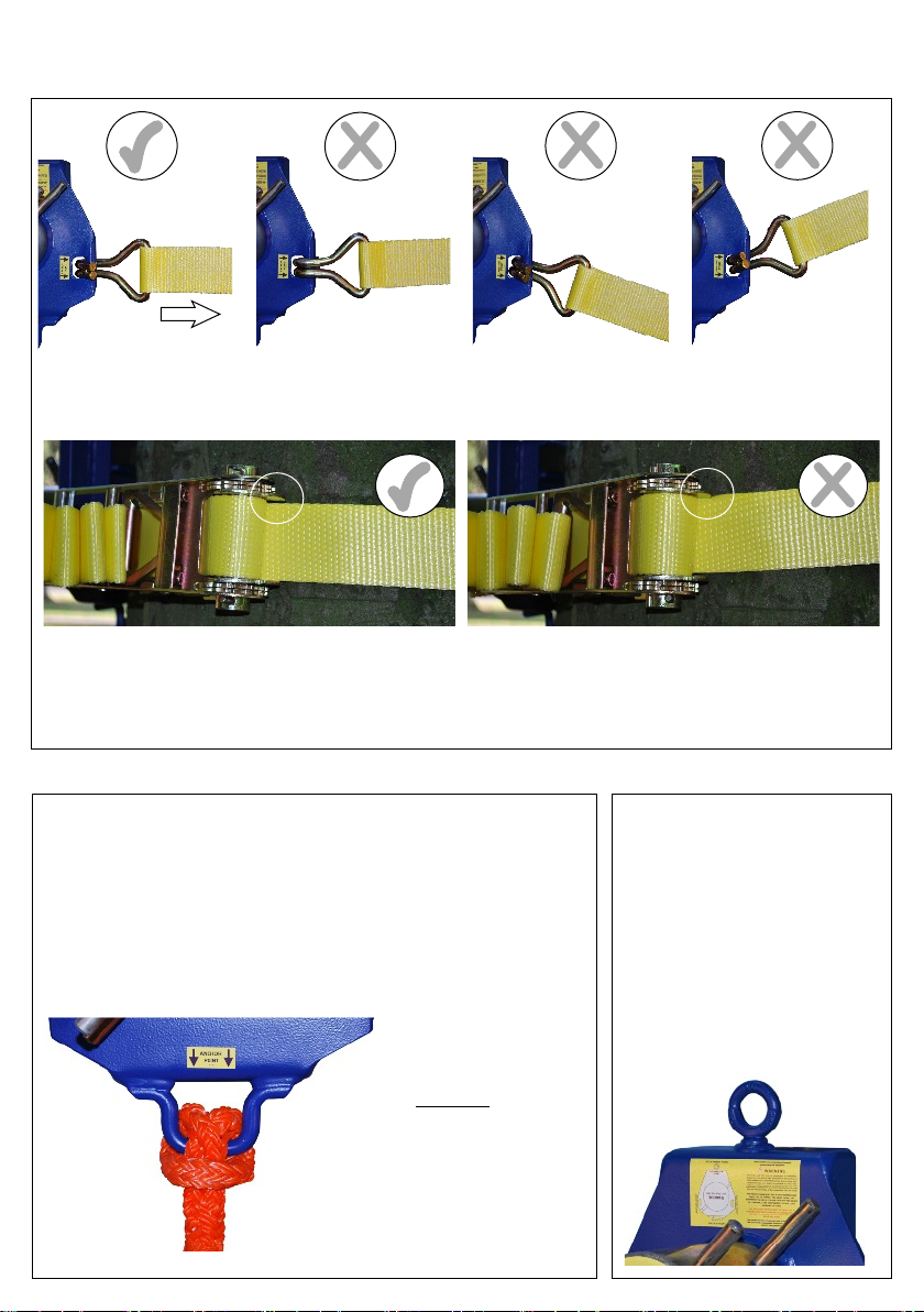
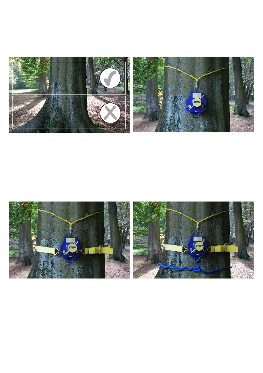
accept any liability if users do not follow the instructions correctly. Only the techniques shown in the diagrams
are authorised. Any other use deviating from those shown may result in serious injury or death.
Prior to each use a complete risk assessment must be carried out to ascertain that the device chosen configures
with and is appropriate to the work being undertaken. The RC device chosen must also be compatible with all
the other components within the system.
Users must always ensure that all components of the work system are suitable for the foreseeable loadings that
may be applied during use. Poor technique and shock loading may cause catastrophic failure of this equipment
and should be avoided. Where a failure of the product may occur a suitable backup system must be installed
and used. All components of the system used with the device must be inspected before and after each
lowering/lifting operation. Retire the RC device from use if there are any tactile or visual signs of wear or
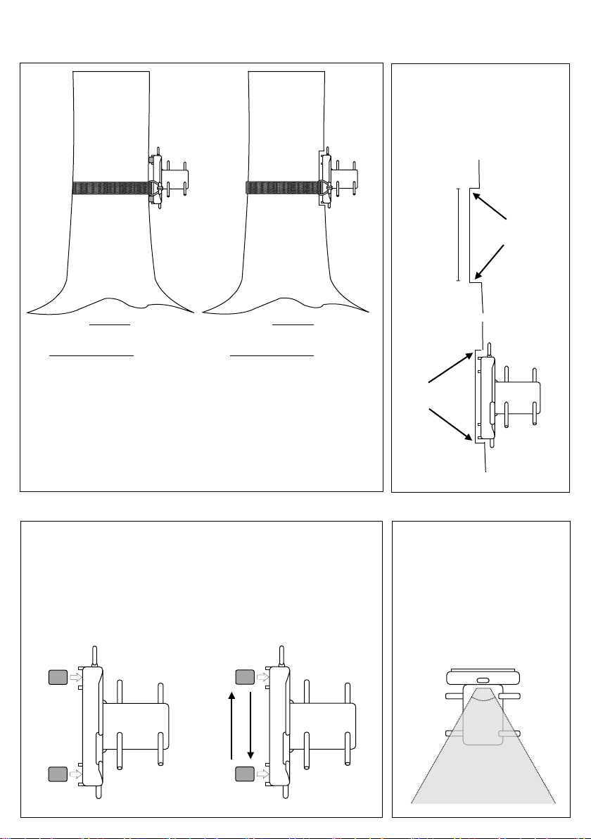
damage. The retention devices must also be inspected & checked for both tension and wear after each lowering
or lifting operation to ensure they are securely attached to the RC device and the mounting point.
The RC Lowering Devices should only ever be used with the correct diameter of rope, You must never exceed
the recommended maximum diameters. Each device has a Working Load Limit (WLL) – This is the maximum
load allowed to be applied to the device either for lifting or lowering above which catastrophic failure will occur.
These values are based on a vertical load being applied and used as specified within these instructions.
Although these devices have been issued with a Working Load Limit (WLL) it is your responsibility to ensure that
all the components used in conjunction with the device are matched equally with their Working Load Limit (WLL)
or Safety Factor (SF) or Safe Working Load (SWL). If you are unsure on a products individual specifications
you should contact the manufacturer. You should never exceed the lowest rated section or component within a
rigging system. When calculating any rigging system the strength of the anchor and attachment points must also
be taken into account.
�RC devices must never be used for lifting or lowering people. They are not intended or rated for use as
Personal Protective Equipment. (PPE)
�Always keep body parts, loose clothing, and debris away from the device when in use.
�Always use appropriate hand protection when operating the device.
�When holding the working line NEVER wrap the line around your hands or other body parts. Always ensure
it can run freely in case you need to release the line in an emergency.
�Do not stand or allow others to stand directly under the load being lowered or under the work being
performed above. Ensure users and other persons are working and operating the device from a safe distance.
�Any potential shock loading must always be kept to an absolute minimum when using the RC device as with
all rigging equipment.
�All connecting devices or components must be retired from use if they are subjected to impact loading.
�To avoid damage to the device you must minimise all if any free fall distance.
�Always maintain control of any lowered load.
�All pivot points and moving parts must be lubricated regularly using a suitable lubrication spray. Ensure no
excess lubrication comes into contact with any area of the textile fixings or working line. Remove all excess
lubrication immediately.
�Products covered under these instructions should never be resold or used by a third party after it has been
used by the original purchaser.
�The manufacturer recommends this product should be inspected prior to use along with periodically
independent inspection in line with UK LOLER 1998.
As part of any method statement we recommend that all users of this equipment must be given a copy
of these instructions. They must read them, understand them and explicitly follow all instructions and
cautions attached. Any person using this equipment should be fully trained and competent in its use
before carrying out any rigging operations.