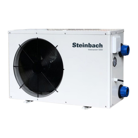
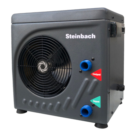
Steinbach MINI User manual

Vertrieben durch
Steinbach International GmbH
L. Steinbach Platz 1
4311 Schwertberg, Austria
helpdesk.steinbach.at
Produktinformationen/ Product information/ Informations relatives au produit/ Informazioni
sul prodotto/ Informacije o izdelku/ Informații despre produs/ Informace o výrobku/ Infor-
macije o proizvodu/ Termékinformáció/Informácie o výrobku/ Продуктова информация/
Ürün bilgileri/ Informacje o produkcie/ Información sobre el producto
steinbach-group.com
Ersatzteile/ Spare parts/ Pièces de rechange/ Parti di ricambio/ Nadomestni deli/ Piese
de schimb/ Náhradní díly/ Zamjenski dijelovi/ Pótalkatrészek/ Náhradné diely/ Резервни
части/ Yedek parçalar/ Części zamienne/ Piezas de recambio
steinbach-group.com/de/ersatzteile
© 2021 Steinbach International GmbH
Nachdruck oder Vervielfältigung (auch auszugsweise) nur mit Genehmigung der Steinbach International GmbH. Diese Druckschrift, einschließlich aller ihrer
Teile, ist urheberrechtlich geschützt. Jede Verwertung außerhalb der engen Grenzen des Urheberrechts ist ohne Zustimmung der Steinbach International
GmbH unzulässig und strafbar. Das gilt insbesondere für Vervielfältigungen, Übersetzungen, Mikroverfilmungen und die Einspeisung und Verarbeitung in
elektronischen Systemen.
Pool Control
Pool Control App
Bedienungsanleitung / User Manual / Mode d'emploi / Istruzioni per l’uso / Operación manual / Návod k obsluze / Használati
útmutató / Navodila za uporabo / Návod na obsluhu / Instrukcja obsługi / Manual de utilizare / Uputstvo za upotrebu /
Pъководство за работа / Kullanım kılavuzu
Wärmepumpe
MINI
de
Wärmepumpe MINI........................................ 6
fr
Pompe á chaleur MINI................................. 47
es
Bomba de calor MINI................................... 89
hu
Hőszivattyú MINI........................................130
sk
Tepelné čerpadlo MINI...............................170
ro
Pompă de căldură MINI............................. 212
bg
Топлинна помпа MINI...............................253
en
Heat pump MINI............................................27
it
Pompa di calore MINI.................................. 68
cs
Tepelné čerpadlo MINI...............................110
sl
Toplotna črpalka MINI................................150
pl
Pompa ciepła MINI.....................................191
hr/bs
Toplinska pumpa MINI...............................233
tr
Isı pompası MINI........................................ 276


1
4 3 2
3
de

Package contents
1
Heat pump
2
Adapter (x2)
1
Hose clamp (x2)
2
Drain connection piece (condensation water)
Components
1
Handle (x2)
2
Water connection, outlet
3
Water connection, inlet
1
Power cable (with RCD power plug)
2
Fan
3
Finned heat exchanger
(C) RCD power plug
1
LED
1
RESET button
2
TEST button
(D) Display: operating and display elements
1
Display
2
ON/OFF button
1
Up button
2
Down button
3
SET button
26

Contents
Overview................................................................................................................................................... 3
Package contents...................................................................................................................................26
General Information............................................................................................................................... 28
Reading and storing the operating manual........................................................................................28
Explanation of Symbols.........................................................................................................................28
Safety.......................................................................................................................................................29
General safety instructions................................................................................................................ 29
Preparation............................................................................................................................................. 32
Checking the delivery for completeness and damage.......................................................................32
Initial cleaning of the device...............................................................................................................32
Preparing the setup location and the connections.............................................................................32
Installation.............................................................................................................................................. 34
Installing adapters on the hose ends.................................................................................................34
Connecting the lines/pipes.................................................................................................................34
Display.....................................................................................................................................................35
Standby mode....................................................................................................................................35
Operating mode.................................................................................................................................35
Parameters........................................................................................................................................ 36
Operation................................................................................................................................................ 37
RCD power plug................................................................................................................................ 37
Activating heating.............................................................................................................................. 38
Showing or setting parameters..........................................................................................................38
Deinstallation..........................................................................................................................................39
Disconnecting the lines/pipes............................................................................................................ 39
Cleaning.................................................................................................................................................. 39
Cleaning the device........................................................................................................................... 39
Test.......................................................................................................................................................... 39
Ice on finned heat exchanger............................................................................................................ 40
Leakage.............................................................................................................................................40
Storage....................................................................................................................................................41
Shutdown in winter............................................................................................................................ 41
Troubleshooting..................................................................................................................................... 42
Technical data.........................................................................................................................................43
Spare parts..............................................................................................................................................44
Declaration of Conformity..................................................................................................................... 45
Disposal.................................................................................................................................................. 45
Disposing of the packaging................................................................................................................45
Disposing of used appliances............................................................................................................45
Disposing of the refrigerant................................................................................................................45
27
en

General Information
Reading and storing the operating manual
This instruction manual is part of this MINI heat pump (in the following also called "device"
or "heat pump"). It contains important information about start-up and operation.
Before using the device, read the operating manual carefully, in particular the safety
instructions. Failure to follow this operating manual may lead to severe injuries or product
damage.
Keep this operating manual for future reference. If you pass this device on to a third party, you must also
supply this operating manual.
Intended use
The device is designed exclusively to heat water passed through it as part of the water treatment
system for private pools.
The salt concentration of the water must not exceed 0.5% (corresponds to 5 g/l or 5,000 ppm).
This device must only be used in outdoor areas.
This device is intended for private use only and is not suitable for commercial use.
Use the device only as described in this operating manual. Any other use is improper and may lead to
product damage or even personal injury. This device is not a toy.
The manufacturer or retailer assume no liability for damage caused by improper or incorrect use.
Fluorinated greenhouse gas - difluoromethane (R32)
The device contains the fluorinated greenhouse gas difluoromethane (R32), which is required for the
functioning of the device.
Industrial name HFKW-32
Common name R32
Chemical name Difluoromethane
Molecular formula CH2F2
Global warming potential (GWP) 675
Further information is indicated on the device or in the "Technical data" section.
Explanation of Symbols
The following symbols and signal words are used in this user manual, on the device or on the
packaging.
Read the user manual. The user manual contains
important addional
informaon.
The user manual contains
important informaon about
maintenance and repairs.
Risk of re! Warning!
Flammable materials.
28

Risk of electric shock!
Warning! Electric voltage.
Products marked with this
symbol conform to
protecon class I.
Do not ghten with tools,
only by hand.
H
a
l
t
e
n
S
i
e
a
l
l
e
Ö
f
f
n
u
n
g
e
n
f
r
e
i
v
o
n
F
r
e
m
d
k
ö
r
p
e
r
n
.
D
o
n
o
t
i
n
s
e
r
t
f
o
r
e
i
g
n
b
o
d
i
e
s
i
n
t
o
t
h
e
s
l
i
t
s
.
Warning
Achtung
Do not insert any objects
into the openings.
Never use sharp knives or other pointed objects to open the packaging.
They might damage the content.
Safety
The following signal words are used in this user manual.
WARNING! This signal symbol/word denotes a hazard with an average
risk level that could lead to death or severe injury if it is not
avoided.
CAUTION! This signal symbol/word denotes a hazard with a low risk
level that could lead to mild or moderate injury if it is not
avoided.
NOTICE! This signal word provides a warning about potential material
damage.
General safety instructions
WARNING!
Danger of death due to unsuitable water temperature!
Long stays in pools with an excessively high or low water temperature can lead to
overheating (body temperature above 38 °C) or hypothermia (body temperature below
35 °C). This can result in fatigue and vertigo, and even fainting or unconsciousness. This may
result in death by drowning in the pool. For pregnant women, there is a risk of deformations or
brain damage to their unborn child, especially during the first trimester.
-Keep the water temperature in a range from 26 °C to 30 °C during normal swimming.
-Do not let children and pregnant women use the pool if the water temperature is above
38 °C.
-Do not let the water temperature rise above 40 °C.
-If in doubt, check the water temperature with a suitable high-resolution thermometer
before going into the water. (The temperature sensor of the heat pump guarantees an
accuracy of approx. ±3 °C.)
29
en

WARNING!
Risk of fire and explosion due to leaking finned heat exchanger!
The refrigerant circuit of the finned heat exchanger contains a highly flammable, odorless gas
under high pressure. Risk of fire and explosion due to uncontrolled escaping of refrigerant.
-Keep heat sources and naked flames away from the heat pump.
-Do not burn or drill into the heat pump.
-Do not use any objects other than those permitted by the manufacturer to speed up the
defrosting process.
-Stop using the heat pump immediately if you suspect a refrigerant leak.
-The refrigerant is odorless. Always keep ignition sources away from the installation site of
the heat pump.
-Contact an authorized qualified person if you suspect refrigerant leaks.
-Observe the national regulations on gas.
-All persons involved in work on the refrigerant circuit must have a valid certificate from an
industry accredited certification body that ensures competence in handling refrigerants
according to a specific assessment recognized by industry associations.
-Take precautions so that the device cannot be damaged while in storage.
-Store the device in a well ventilated location where the room size corresponds to the
room area specified for operation.
WARNING!
Risk of injury through insufficient qualification!
Insufficient experience or skills for handling the required tools and insufficient knowledge of
regional or normative regulations for the required work can lead to severe injuries or material
damage.
-Assign all work whose risks you cannot estimate due to insufficient personal experience
to a qualified expert.
WARNING!
Risk of electric shock!
Faulty electric installation or excess mains voltage can cause an electric shock.
-Have the installation, initial start-up and maintenance of the heat pump carried out by
authorized specialists only.
-Do not start work on the heat pump before all safety instructions have been complied
with.
-Work on the heat pump may only be carried out when it is de-energized.
-Only connect the heat pump if the mains voltage of the socket matches that on the type
plate.
-Only connect the heat pump to an easily accessible socket so that you can quickly
disconnect the heat pump in the event of a fault.
-Do not operate the heat pump if there is visible damage or if the power cable or power
plug is defective.
-If the power cable of the heat pump is damaged, it must be replaced by the manufacturer,
its customer service or a qualified person to prevent hazards.
-Do not open the housing. Let specialists perform any repairs. All liability and warranty
claims will be void in the case of arbitrary repairs, improper connection or wrong
operation.
-Only parts that match the original device data may be used for repairs. This heat pump
contains electrical and mechanical parts that are essential for protection against sources
of danger.
-Do not operate the heat pump with an external timer or a separate remote control
system.
30

-Do not immerse the heat pump, power cable or power plug in water or other liquids.
-Never touch the power plug with wet hands.
-Never pull the power cable to disconnect the power plug from the socket. Always
disconnect by holding the power plug.
-Never use the power cable as a carrier handle.
-Keep the heat pump, power plug and power cable away from open fires and hot
surfaces.
-Make sure that the power cable does not present a trip hazard.
-Do not bend the power cable or position it over sharp edges.
-Make sure that children do not put objects into the heat pump.
-Keep the openings free from foreign objects.
-When the heat pump is not in use, is being cleaned, or if a fault occurs, always switch off
the heat pump and disconnect its power plug from the socket.
-Make sure that the actual operating voltage does not deviate from the nominal value by
more than 10% (see "Technical Data").
-As a protective device, the heat pump must have a circuit breaker with a 16 A slow-blow
fuse; this protective device may only feed the heat pump. Even when using a protective
device with all-pole disconnection, it must still have a differential switch with a differential
current not exceeding 30 mA.
-Make sure that the electrical system to which the heat pump is connected contains a
grounding conductor.
-If a power plug is going to be installed for connection to the mains, it must have a
protection level of at least IPX4 and a terminal for connecting the grounding conductor.
The same applies to the power supply cable, which must also have a grounding
conductor.
-Protect the power cable and the power plug from rain and moisture.
-Protect the power cable and the power plug from damage.
WARNING!
Risk of injury for persons with personal impairments or a lack of experience and
expertise!
Improper handling of the device can lead to severe injury or damage to the device.
-This heat pump can be used by children above the age of 8 and by persons with reduced
physical, sensory or mental capacities or lack of knowledge and expertise if they are
supervised or have been instructed concerning the safe handling of the heat pump and
comprehend the resulting risks. Children must not play with the heat pump. Children
must not clean and service the device.
-Do not leave the device unattended while in use.
-Only allow others to access the device after they have read and comprehended the
entire manual or have been instructed about the intended use and the associated risks.
-Never let persons with reduced physical, sensory or mental capacities (such as children
or people under the influence of alcohol) or a lack of experience and knowledge (such as
children) unsupervised near the device.
CAUTION!
Risk of injury when moving heavy equipment!
The device is heavy! Incorrect lifting or uncontrolled toppling of the device can lead to injuries
or damage the device.
-Always carry or tilt the device with the help of at least one other person, never alone.
-Make sure that your posture is correct (straight back, secure footing, etc.).
-Use transport aids (such as a lifting truck or roller board).
-Wear protective equipment, such as safety shoes or gloves.
31
en

Preparation
WARNING!
Packaging materials pose a risk of suffocation!
Catching your head in the packaging foil or swallowing other packaging materials can cause
death. There is a higher risk for children and mentally challenged persons who cannot
estimate the hazard potential due to lack of knowledge and experience.
-Prevent children and mentally challenged persons from playing with the packaging
materials.
NOTICE!
Careless opening of the packaging, especially with the help of sharp or pointed objects, may
cause damage to the device.
-Open the packaging very carefully.
-Do not penetrate the packaging with sharp or pointed objects.
Checking the delivery for completeness and damage
1. Open the packaging carefully.
2. Take all parts out of the packaging.
3. Check the completeness of the delivery.
4. Check the delivery for damage.
Initial cleaning of the device
1. Remove the packaging materials and all protective foils if present.
2. Clean all parts of the package content as described in the "Cleaning" section.
The device has been cleaned and is ready for use.
Preparing the setup location and the connections
Careful selection and good preparation of the setup location significantly simplifies installation and
operation of the heat pump. The following requirements must be met or considered:
- Outdoor setup location
-Protection from flooding and severe exposure to rain or sprinkler systems
-Stable, level ground not subject to the influence of water
-Required minimum distance to walls or objects (see Fig. E)
-Required minimum distance of 2 m to the pool
-Easy connection of the water pipes
-Easy connection of the power supply
-Easy access to the display
-Ability to drain condensation water
-Surroundings not sensitive to vibration and noise
For a still more efficient use of the heat pump, we recommend to add our Steinbach
bypass set (item no. 060045).
32

Preparing the setup location
2120 mm
965 mm
300 mm
1500mm
300 mm
300 mm
E
F
1. Set up the heat pump exactly as it will be installed later.
33
en

2. Lay the hoses from the water treatment system to the setup location of the heat pump (see Fig. F).
Make sure that there is no tension on any of the lines routed to the heat pump and that they are not
in the way.
3. Lay the supply line for the heat pump's power supply (see section "Technical data").
Use an extension cable or a socket with the required protection class for the environmental
conditions of the connection site!
The setup location is prepared.
Installation
Installing adapters on the hose ends
The heat pump is always the last link in the water treatment system. If a filter or salt
system or similar is used, it must be connected upstream of the heat pump so that the
filtered, treated water flows through the heat pump.
1. Clean large-particle soiling from the connection points of the heat pump
1
, the adapters
2
and
the hose ends of the water pipes.
2. Screw an adapter
2
onto the outlet water connection
6
.
3. Screw an adapter
2
onto the inlet water connection
7
.
4. Attach the hose end of the drain line with a hose clamp
3
and the adapter
2
on the outlet water
connection
6
(see Fig. 1).
5. Connect the hose end of the feed line with a hose clamp
3
and the adapter
2
on the inlet water
connection
7
(see Fig. 1).
The adapters are installed on the hose ends.
Connecting the lines/pipes
Establishing the power supply
The MINI heat pump cannot be operated with an external timer and you need to manually switch the
pump on and off via the RCD power plug.
1. Connect the RCD power plug
C
to the power supply prepared at the setup location.
The power supply is established.
Connecting a drain pipe for condensation water (optional)
1. Insert the drain connection piece
4
into the hole in the base plate.
2. Attach the drain pipe (garden hose) for condensation water to the drain connection piece
4
.
The drain pipe for condensation water is connected.
1
23
34

Display
Standby mode
In standby mode, the heat pump is ready for operation but it is deactivated. By pressing the On/Off
15
button, the heat pump switches to operating mode.
After switching on, the heat exchanger has to heat up first before the heat pump is ready
for use in operating mode. This process can take up to 90 seconds.
Display:
-The display
14
shows "OFF".
Operating mode
In operating mode, the heat pump heats the water to the set water temperature. The standard value for
the set water temperature is 27 °C. You can set the water temperature to a value between +15 °C and
+35 °C. By pressing the On/Off
15
button, the heat pump switches to standby mode. The desired water
temperature can be set by pressing the Up button
16
or the Down button
17
.
After switching off, the heat exchanger has to cool down before the fan stops running.
This process can take up to 90 seconds.
Set
G14 15
35
en

Display:
- The display
14
shows the current water temperature.
Saving energy
To reduce energy consumption and related costs, you can take the following measures:
•
If you do not use the pool for a few days (e.g., on weekends), keep the current water
temperature approximately at the desired water temperature. The heat pump needs
time to heat up the pool water. If there is a large temperature difference between the
current water temperature and the desired water temperature, it can take several
days until the desired water temperature is reached.
•
If do not use the pool for more than a week, shut off the heat pump or reduce the set
water temperature.
•
Do not use the heat pump when the ambient temperature falls below 5 °C.
•
Cover the pool to prevent heat loss due to wind.
Parameters
In operating mode, the heat pump allows you to display temperatures or make settings by pressing the
SET button
18
. The desired parameter can be selected by pressing the Up button
16
or the Down
button
17
.
Display:
-The display
14
shows the selected parameter.
Available parameters:
The heat pump has two temperature sensors that measure the following temperatures:
Set
H14 15 16
17
Set
I14 16
18 17
36

Parameters Display range Example
A current water temperature at inlet -19 °C to +99 °C A 25 (25 °C)
C current temperature at heat exchanger -19 °C to +99 °C C 9 (9 °C)
The heat pump has eight adjustable parameters:
Parameters Setting range Default
1 desired water temperature 15 °C to 35 °C 1 27 (27 °C)
2 Temperature difference for restart 1 °C to 10 °C 2 2 (2 °C)
4 Automatic restart 0 to 1 4 1 (1 °C)
5 Duration for automatic defrost function 10 min to 90 min 5 40 (40 min)
6 Temperature setting for automatic defrost function -30 °C to 0 °C 6 0 (0 °C)
7 Temperature setting for exiting automatic defrosting 1 °C to 30 °C 7 2 (2 °C)
8 Exit automatic defrosting 10 min to 40 min 8 30 (30 min)
Operation
WARNING!
Risk of death when operating the water treatment system during bathing.
Hair or clothing might get sucked into the suction openings of the pool and in extreme cases
trap persons under water and prevent them from surfacing again.
-Never operate water treatment system devices while persons are in the pool.
-Prevent any access to the pool for as long as water treatment system devices are in use.
CAUTION!
Risk of injury!
A damaged device or damaged accessories may cause injuries.
-Check the device and the accessories (see section "Testing").
NOTICE!
Reduced or blocked ventilation of the heat pump can lead to faulty extraction of heat or
moisture. This might cause mold or overheating of the finned heat exchanger.
-Clean the grate in front of the fan impeller and the fins of the heat exchanger at regular
intervals and make sure that dirt such as leaves or similar does not get into the heat
exchanger.
-Make sure that the grate on the heat exchanger is never covered up and that the air can
circulate freely through the device.
RCD power plug
The RCD power plug consists of a safety plug and a residual current circuit breaker. The safety plug
must be connected to a matching socket with an earthed protective conductor. The residual current
circuit breaker disconnects the heat pump from the voltage as soon as unexpectedly high currents that
are dangerous for persons flow through the heat pump (e.g. short circuit through electroconductive parts
of the housing).
37
en

Testing the residual current circuit breaker
1. Connect the RCD power plug to the power supply prepared at the setup location.
2. Press the RESET button.
The LEDis lit. The heat pump is supplied with power and is in standby mode.
3. Press the TEST button.
The LEDgoes off. The heat pump is disconnected from power and the display goes off.
4. Press the RESET button.
The LEDis lit. The heat pump is supplied with power and is in standby mode.
The residual current circuit breaker of the RCD power plug has been tested successfully.
Activating heating
The adjustable temperature range in operating mode is between 15 to 35°C. The start value of the set
water temperature is 27°C.
The water in the pool is heated up fastest at maximum throughput of the water through
the heat pump (see section "Technical data"). However, increasing the flow rate reduces
the time spent at the heat exchanger, which means that the difference in temperature
between the water in the pool and the heated water at the pool inlet is lower overall and
therefore less noticeable. Please measure and record the change in the current water
temperature every 30 minutes to determine the actual heating of the pool water.
Activating operating mode
1. Press the RESET
12
button.
The LED
11
is lit. The heat pump is supplied with power and is in standby mode.
2. Press the ON/OFF button
15
.
The heat pump
1
is in operating mode and the display
14
shows the current water temperature in °C.
Setting the desired water temperature
1. Repeatedly press the Up button
16
or the Down button
17
.
The display
14
shows the desired water temperature in °C.
The heat pump does not work when the set desired water temperature is below the
currently measured water temperature.
Showing or setting parameters
The heat pump has 9 parameters that can be shown or set via the display
D
(see "Parameters").
Showing parameters
1. Press and hold the SET button
18
for 5 seconds while the heat pump is in operating mode.
The display
14
shows "A".
2. Repeatedly press the Up button
16
or the Down button
17
.
The display
14
shows the desired parameter (see "Parameters").
3. Press the SET button
18
to select the desired parameter.
The value of the selected parameter blinks on the display
14
.
Setting parameters
1. Repeatedly press the Up button
16
or the Down button
17
.
38

The desired value of the selected parameter blinks on the display
14
.
2. Press the SET button
18
.
The desired value of the selected parameter is set.
Deinstallation
CAUTION!
Risk of injury when moving heavy equipment!
The device is heavy! Incorrect lifting or uncontrolled toppling of the device can lead to injuries
or damage the device.
-Always carry or tilt the device with the help of at least one other person, never alone.
-Make sure that your posture is correct (straight back, secure footing, etc.).
-Use transport aids (such as a lifting truck or roller board).
-Wear protective equipment, such as safety shoes or gloves.
Disconnecting the lines/pipes
Disconnecting the power supply
1. Put the heat pump into standby mode (see section "Display").
2. Press the RESET
12
button.
3. Disconnect the RCD power plug
C
from the power supply.
The heat pump is disconnected from the power supply.
Disconnecting the water lines
1. Deactivate the water treatment pump.
2. Undo the hose clamps
3
on the adapters
2
.
3. Pull the hose end off the adapter
2
at the inlet water connection
7
.
When removing the hose end of the water line, hold it with the opening facing upward so that
residual water in the hose does not uncontrollably run out.
4. Unscrew the hose end from the adapter
2
at the outlet water connection
6
.
When removing the hose end of the water line, hold it with the opening facing upward so that
residual water in the hose does not uncontrollably run out.
The water lines are disconnected.
Cleaning
Cleaning the device
Wipe the surface with a dry cloth.
Test
Check the following before each use:
-Is there visible damage on the device?
-Is there visible damage on the control elements?
-Are the accessories in flawless condition?
- Are all lines in flawless condition?
-Are the ventilation slots unobstructed and clean?
Do not start up a damaged device or damaged accessories. Have them checked by the manufacturer or
its customer service or a qualified service technician.
39
en

WARNING!
Risk of fire and explosion due to leaking finned heat exchanger!
The refrigerant circuit of the finned heat exchanger contains a highly flammable, odorless gas
under high pressure. Risk of fire and explosion due to uncontrolled escaping of refrigerant.
-Keep heat sources and naked flames away from the heat pump.
-Do not burn or drill into the heat pump.
-Do not use any objects other than those permitted by the manufacturer to speed up the
defrosting process.
-Stop using the heat pump immediately if you suspect a refrigerant leak.
-The refrigerant is odorless. Always keep ignition sources away from the installation site of
the heat pump.
-Contact an authorized qualified person if you suspect refrigerant leaks.
-Observe the national regulations on gas.
-All persons involved in work on the refrigerant circuit must have a valid certificate from an
industry accredited certification body that ensures competence in handling refrigerants
according to a specific assessment recognized by industry associations.
Ice on finned heat exchanger
A layer of ice (water condensation) may form on the finned heat exchanger during operation of the heat
pump. This phenomenon is to be expected. Depending on the ambient conditions, it is possible that the
layer of ice is not thawed completely by the automatic defrost function which may lead to a performance
drop and damage to the heat pump.
You can personalize the automatic defrost function:
-(5) Duration for automatic defrosting: sets the duration of the automatic defrost function in minutes.
-(6) Temperature setting for automatic defrosting: as soon as the "current temperature at heat
exchanger" (C) has dropped below this value in °C, the automatic defrost function starts.
-(7) Temperature setting for stopping automatic defrosting: as soon as the "current temperature at
heat exchanger" (C) has exceeded this value in °C, the automatic defrost function stops.
-(8) Temperature setting for stopping automatic defrosting: as soon as automatic defrosting exceeds
the set duration in minutes, the automatic defrost function stops.
Do not use any objects other than those permitted by the manufacturer to speed up the
defrosting process!
Leakage
If fluids are coming out of the heat pump, it can be one of the following:
-Condensation water
-Pool water
- Refrigerant
Condensation water
Condensation water forming during operation is normal. There is no damage. The surface of the finned
heat exchanger gets cold, humidity in the ambient air condenses and, in extreme cases, freezes.
Condensation water collects in the bottom tray and is discharged through a hole and via the drain
connection piece
4
. If the drain connection piece
4
is plugged up, the condensation water cannot
drain from the heat pump and larger amounts collect in the heat pump.
Pool water
Leaking pool water indicates that:
•
the hose is not correctly installed on the adapter
2
.
•
the adapter
2
is not correctly connected to the heat pump
1
.
•
the seal in the adapter
2
is defective or missing.
•
the flow pipe inside the heat pump has a leak.
40

Refrigerant
Leaking refrigerant indicates that the refrigerant circuit in the finned heat exchanger has a leak. Contact
a qualified person immediately if you detect a leak in the refrigerant circuit.
Keep in mind that refrigerants are odorless.
Storage
As soon as the outside temperature permanently falls below +5 °C, the heat pump should be stored
away for the winter to prevent damage through ice formation (frost bursts).
Permanently installed water pipes do not necessarily have to be deinstalled. If the
location of the heat pump is protected against heavy soiling and strong weather
influences, it is sufficient to drain the water from the heat pump and the water pipes.
Shutdown in winter
1. Disconnect all lines and pipes (see section "Deinstallation").
2. Clean the heat pump thoroughly (see section "Cleaning").
3. After thorough drying, store the heat pump in a dry, frost-free place (>+5 °C).
The heat pump is stored away for the winter.
41
en

Troubleshooting
Problem Possible cause Remedy
The display is not lit The power plug is not properly
connected to the socket/
extension cable.
Disconnect the power plug from the
socket/extension cable and reconnect it.
The RCD power plug is in the
triggered state (the LED is not
lit).
Press the RESET button
12
. If the LED is
not continuously lit, contact an authorized
electrician.
No voltage is present at the
socket/extension cable.
Contact an authorized electrician.
The heat pump does not start. The heat exchanger has not
reached its operating
temperature yet.
Wait for 90 seconds after activation.
The current water temperature
is higher than or equal to the set
water temperature.
Set a higher temperature or wait until the
current water temperature drops below
the set water temperature.
The water in the swimming pool
does not reach the desired
temperature even though the heat
pump is running.
The operating time of the heat
pump was too short for it to
reach the set water temperature.
Wait for 24-48 hours.
Ice has formed on the finned heat
exchanger.
The ambient temperature is too
low/the humidity is too high.
Activate manual defrosting (see section
"Operation").
The gas pressure in the
refrigerant circuit is too low (see
section "Testing").
Contact an authorized qualified person.
Liquid is escaping. Condensation water has
accumulated.
Check the drain connection piece and
drain line for blockage.
The water connections are
leaking.
Check the seal and firmly tighten the
union nuts.
The water outlet is leaking (see
section "Testing")
Contact an authorized qualified person.
The refrigerant circuit is leaking
(see section "Testing")
Contact an authorized qualified person.
Display: error message P1 The temperature sensor at the
inlet is defective or does not
emit a signal.
Contact an authorized qualified person.
Display: error message P3 The temperature sensor at the
heat exchanger is defective or
does not emit a signal.
Contact an authorized qualified person.
Display: error message P5 Pressure in refrigerant circuit is
too low.
Contact an authorized qualified person.
42
Other manuals for MINI
1
Table of contents
Other Steinbach Heat Pump manuals

Steinbach
Steinbach BP-39WS-B Mini User manual

Steinbach
Steinbach Waterpower 8500 User manual

Steinbach
Steinbach MINI Series User manual

Steinbach
Steinbach Waterpower 8500 Mounting instructions

Steinbach
Steinbach MINI User manual

Steinbach
Steinbach BP-39WS-B Mini User manual

Steinbach
Steinbach BP-50HS-A1/049202 User manual

Steinbach
Steinbach BP-50HS-A1 User manual

Steinbach
Steinbach heatUP 650 User manual