stellar labs TireMan 16160 User manual

TireMan Package
16160
Owner’s Manual
Stellar Industries, Inc.
190 State Street
PO Box 169
Garner, IA 50438
800-321-3741
Fax: 641-923-2811
www.stellarindustries.com
Subject to Change without Notification.
© 2019 Stellar Industries, Inc.
Rev 1
PN 98584
Installation • Assembly Drawings • Parts
Notice: A copy of this manual must remain with the equipment at all times.
For a printable download copy, please visit: www.stellarindustries.com

Page ii | Stellar®TMP16160 Owner’s Manual
Model TM16160 Manual Revisions
Date of Revision Section Revised Description of Revision
MODELNO.SERIAL NO.
DATE
MADE IN THE U.S.A. BY STELLAR INDUSTRIES, INC.
PNC5942
®
PATENTINFORMATION
http://www.stellarindustries.com/ip
MODEL NO.SERIAL NO.
DATE
MADE IN THE U.S.A. BY STELLAR INDUSTRIES, INC.
PN C5942
®
PATENT INFORMATION
http://www.stellarindustries.com/ip
Serial Tag
Location

Stellar®TMP16160 Owner’s Manual | Page iii
Table of Contents
Introduction.............................................................................................................................. iv
Chapter 1 - Specifications........................................................................................................... 1
Model TM16160 Capacity ....................................................................................................... 1
Model TM16160 Specifications................................................................................................ 2
TM16160 Dimensional Layout .................................................................................................. 3
Chapter 2 - Installation ................................................................................................................ 5
General Installation .................................................................................................................. 5
Installer Notice........................................................................................................................ 5
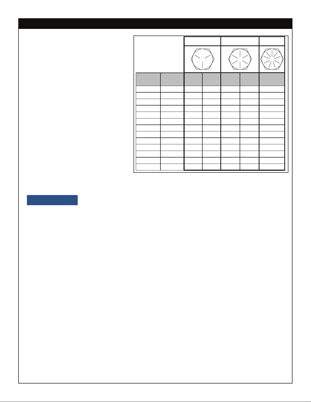
Torque Data Chart................................................................................................................. 6
Installation Overview ............................................................................................................. 7
Mounting Kit Drawing ............................................................................................................ 7
Hydraulic Installation ................................................................................................................ 8
Hydraulic Pressure Settings ...................................................................................................... 9
Face Seal/O-Ring Size Chart ................................................................................................... 9
Main Hydraulic Kit - PN 69197................................................................................................ 10
TireMan Hydraulic Kit - PN 68660........................................................................................... 11
Control Kit - PN 92667 ............................................................................................................. 12
Grease Kit - PN 68798 ............................................................................................................. 13
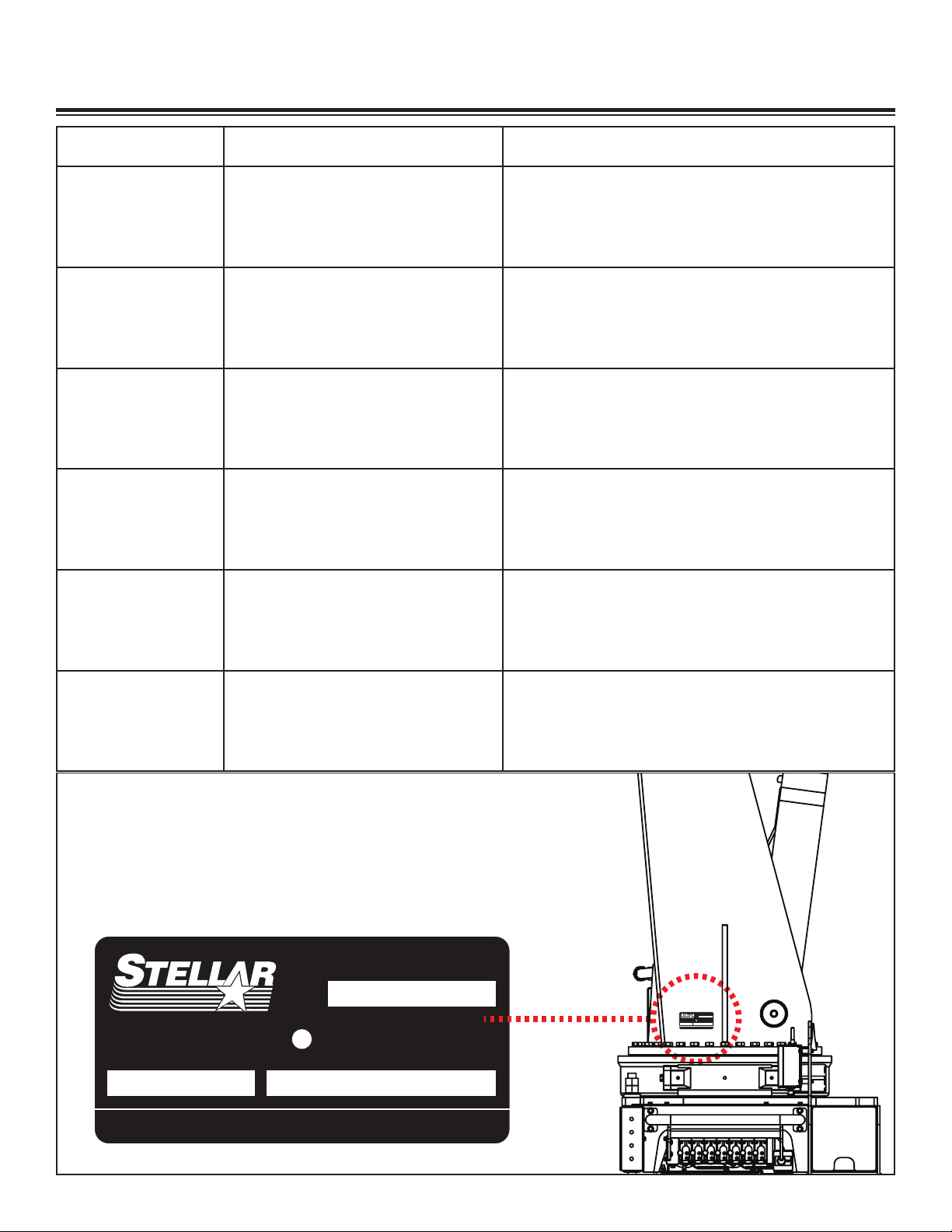
Main Decal Placement - PN 98664....................................................................................... 14
TireMan Decal Placement - PN 37845.................................................................................. 15
Chapter 3 - Assembly Drawings ............................................................................................... 17
Base Assembly - PN 47880 ..................................................................................................... 17
Optional Load Sensor Base - PN 67062 ................................................................................ 18
Stabilizer Assembly - PN 48689............................................................................................... 19
Bearing Assembly - PN 18471 ................................................................................................ 20
Gearbox - PN 60505 ............................................................................................................... 21
Valve Bank - PN 42802............................................................................................................ 22
Mast Assembly - PN 18073 ..................................................................................................... 23
Main Boom Assembly - PN 68021.......................................................................................... 24
Main Cylinder Assembly - PN 20694...................................................................................... 25
Outer Cylinder Assembly - PN 50628 .................................................................................... 26
Extension Boom Assembly - PN 70661 .................................................................................. 27
TireMan Assembly - PN 67861 ................................................................................................ 28
TireMan Assembly (cont.) - PN 67861 ................................................................................... 29
Stabilizer Cylinder Assembly - PN 48383 ............................................................................... 30
Reservoir Assembly - PN 86356 .............................................................................................. 31
Optional 15 Ton Hook Kit - PN 55138..................................................................................... 32
Radio Transmitter - PN 89149/93084...................................................................................... 33
Chapter 4 - Replacement Parts ................................................................................................ 35

Page iv | Stellar®TMP16160 Owner’s Manual
Introduction
A copy of this manual is provided with every tire manipulator (TM) and can be found in
the hard plastic manual case that is installed on the chassis. A copy of this manual shall
remain with the TM at all times.
Throughout the manual, three signal words will be used to bring attention to important
items:
A NOTICE signal word indicates a practice not related to physical injury.
A WARNING signal word indicates a hazardous situation which, if not
avoided, could result in death or serious injury.
A DANGER signal word indicates a hazardous situation which, if not
avoided, will result in death or serious injury.
Information contained within this manual does not cover operation, maintenance, or
troubleshooting. Please refer to the Large OTR Tire Manipulator Manual for details on these
items.
This manual is not binding. Stellar Industries, Inc. reserves the right to change, at any
time, any or all of the items, components, and parts deemed necessary for product
improvement or commercial/production purposes. This right is kept with no requirement or
obligation for immediate mandatory updating of this manual.
In closing:
If more information is required or technical assistance is needed, or if you feel that any
part of this manual is unclear or incorrect, please contact the Stellar Customer Service
WARNING
NOTICE
DANGER
For Technical Questions, Information, Parts, or Warranty, Call Toll-Free at
800-321-3741
Hours: Monday - Friday, 8:00 a.m. - 5:00 p.m. CST
Or email at the following addresses:

Stellar®TMP16160 Owner’s Manual | Page 1
Chapter 1 - Specifications
Model TM16160 Capacity
Capacity: 16,500 lbs @15 ft (7,484 kg @ 4.57m)
Clamping Span: 40” to 158” (102 cm to 401 cm)
Clamp Cylinders: 4.50” (11.43 cm) bore with pilot operated check valves
Tilt Cylinder: Provided by crane extension boom
Body Rotation: 315º power
Rotation System: Worm gear
Clamping Pad Rotation: Continuous 360º power
TireMan Tilt: +80º to -20º
Hydraulic Controls: Incorporated with the crane controls
Approximate Shipping Weight: 6,000 lbs (2,722 kg)
15’(4.57m)
16500lbs(7484kg)
ROTATION
17’(5.18m)
14000lbs(6350kg)
20’(6.10m)
12000lbs(5443kg)
MAXIMUM RATED LOAD
16500 LBS
EXCEEDING MAXIMUM RATED LOAD WILL
DAMAGE EQUIPMENT AND VOID WARRANTY
37847
7484 KG

Page 2 | Stellar®TMP16160 Owner’s Manual
Model TM16160 Specifications
Tire Manipulator Rating 280,000 ft-lbs (38.71 ton meters)
Tire Manipulator Capacity 16,500 lbs @15 ft (7,484 kg @ 4.57m)
Standard Length 13’ 2” (4.01 m) from CL of TM main rotation
Main Extension Hydraulic 37” (94.0 cm)
Clamping Span 40” to 158” (102 cm to 401 cm)
Maximum Horizontal Reach 22’ 8” (6.91 m) from CL of TM main rotation (with TM clamp open)
Cylinder Specifications
Inner Lift Cylinder: 9” (22.9 cm) bore with integral pilot operated counterbalance
valves
Outer Lift Cylinder: 7” (17.8 cm) bore with integral pilot operated counterbalance
valves
Extension Cylinder: 6” (15.2 cm) bore with integral pilot operated counterbalance
valves
Main Rotation 315 degree power
Main Rotation System Planetary Gear w/ Pinion
TireMan Rotation 315 degree power
TireMan Rotation System Worm gear
Clamping Pad Rotation Continuous 360 degree power
TireMan Tilt +80 degree to -20 degree
Power Supply Required PTO & Pump - 16 gpm @ 4,400 psi (60 lpm @ 304 bar)
Controls Fully Proportional Paddle Controls for all functions.
Stowed Height (Above Truck Frame) 114” (289.6 cm)
Mounting Space Required 48” (121.9 cm)
Chassis RBM (Recommended) 3,360,000 in-lb
Approximate Shipping Weight 19,000 lbs (8617 kg)

Stellar®TMP16160 Owner’s Manual | Page 3
40
158
TM16160 Dimensional Layout

Page 4 | Stellar®TMP16160 Owner’s Manual
This page intentionally left blank.

Stellar®TMP16160 Owner’s Manual | Page 5
Installer Notice
According to Federal Law (49 cfr part 571), each final-stage manufacturer shall complete
the vehicle in such a manner that it conforms to the standards in effect on the date of
manufacture of the incomplete vehicle, the date of final completion, or a date between
those two dates. This requirement shall, however, be superseded by any conflicting
provisions of a standard that applies by its terms to vehicles manufactured in two or more
stages.
Therefore, the installer of Stellar®Tire Manipulators and Bodies is considered one of the
manufacturers of the vehicle. As such a manufacturer, the installer is responsible for
compliance with all applicable federal and state regulations. They are required to certify
that the vehicle is in compliance with the Federal Motor Vehicle Safety Standards and
other regulations issued under the National Traffic and Motor Vehicle Safety Act.
Please reference the Code of Federal Regulations, title 49 - Transportation, Volume 5 (400-
999), for further information, or visit http://www.gpoaccess.gov/nara/index.html for the full
text of Code of Federal Regulations.
Chapter 2 - Installation
General Installation
This chapter is designed to serve as a general guide for the installation of a Stellar TM16160
on a Stellar Service Body. Each installation is considered unique so certain portions of this
chapter may or may not apply to your direct application. If a question should arise during
the installation process, please contact Stellar Customer Service at (800) 321 3741.
This tire manipulator (TM) is designed for use with a Stellar Service Body installed on
a vehicle that meets the minimum chassis requirements of the TM. It is the installer’s
responsibility to assure that the TM is mounted on a platform that will support the maximum
rating of this TM.
Do not install this TM on a body not capable of handling the loads
imposed on it. Failure to do so may result in serious injury or death.
When installing welder units to the service bodies, it is highly
recommended that a surge protector is installed on the chassis batteries to protect the TM
radio receiver, wiring and other electronic devices from an unexpected electrical spike
or surge. Failure to do so could result in extensive damage to the service body and TM
electrical circuit.
WARNING
NOTICE

Page 6 | Stellar®TMP16160 Owner’s Manual
When using the torque data in the
chart, the following rules should be
observed:
• Bolt manufacturer’s particular
specifications should be consulted
when provided.
• Flat washers of equal strength
must be used.
• All torque measurements are
given in foot-pounds. To convert
to inch-pounds, multiply by 12.
• Torque values specified are for
bolts with residual oils or no special
lubricants applied.
• Torque values for socket-head
capscrews are the same as for
Grade 8 capscrews.
• Do not use these values if a different torque value or tightening
procedure is given for a specific application. Torque values listed are for general use
only. Check tightness of fasteners periodically.
• Shear bolts are designed to fail under predetermined loads. Always replace shear bolts
with identical grade.
• Fasteners should be replaced with the same or higher grade. If higher grade fasteners
are used, these should only be tightened to the strength of the original.
• Tighten plastic insert or crimped steel-type lock nuts to approximately 110 percent of the
dry torque values shown in the chart below, applied to the nut, not to the bolt head.
Tighten toothed or serrated-type lock nuts to the full torque value. Note: “Lubricated”
means coated with a lubricant such as engine oil, or fasteners with phosphate and oil
coatings. “Dry” means plain or zinc plated without lubrication. Tighten lubricated bolts
to approximately 80% of dry bolts.
Size Bolt DIA Plain Plated Plain Plated Plated
(DIA-TPI) (Inches) (Ft-Lb) (Ft-Lb) (Ft-Lb) (Ft-Lb) (Ft-Lb)
5/16-18 0.3125 17 13 25 18 22
3/8-16 0.3750 31 23 44 33 39
7/16-14 0.4375 49 37 70 52 63
1/2-13 0.5000 75 57 105 80 96
9/16-12 0.5625 110 82 155 115 139
5/8-11 0.6250 150 115 220 160 192
3/4-10 0.7500 265 200 375 280 340
7/8-9 0.8750 395 295 605 455 549
1-8 1.000 590 445 910 680 823
1 1/8-7 1.1250 795 595 1290 965 1167
1 1/4-7 1.2500 1120 840 1815 1360 1646
1 3/8-6 1.3750 1470 1100 2380 1780 2158
1 1/2-6 1.500 1950 1460 3160 2370 2865
GRADE 5 GRADE 8 GRADE 9
Torque Data Chart
NOTICE

Stellar®TMP16160 Owner’s Manual | Page 7
1. Relocate any obstructions on the frame that will be in the way of mounting the tire manipulator (TM).
2. Measure the inside of the frame rails and cut the frame support to this length. Ensure that the frame
supports have a tight fit between the frame rails.
3. Set the TM on the chassis and allow a minimum of 3” from the cab.
4. Make certain that the frame supports are installed square, cut to length in such a way as to support the
frame flanges with the tie down rods are torqued.
5. Install the TM tie downs. Start at one corner and tighten both tie downs to 200 ft-lbs. Move to the diagonal
set and tighten to 200 ft-lbs. Tighten the remaining 2 corners. Continue this pattern at 200 ft-lb increments
until 500-550 ft-lbs is achieved. Be sure the mounting block stays perpendicular to the frame rail as they are
tightened down.
6. Connect the pressure and return lines per the hydraulic kit.
7. Connect the electrical power and ground wires. Ground preferably connected to battery.
8. With the TM and outriggers in the stored position, check the reservoir for oil and fill if necessary.
9. Operate the TM for several cycles. Fully cycle the cylinder in both directions (blow past relief) to remove
any air from the system.
Installation Overview
Mounting Kit Drawing
.YTQNOITPIRCSEDTRAPMETI.YTQNOITPIRCSEDTRAPMETI
8GNIKCOLPOT8RGHH7-52.1TUN43885400051KCOLBGTM45081
211677 PLATE MOUNTING 23000468978NUT 1.25-7 HHGR816
4ENARC00051TROPPUSEMARF202878DORNWODEIT894413
49180WASHER 1.25 SAE FLAT YELLOW GR816
PN 16659

Page 8 | Stellar®TMP16160 Owner’s Manual
Hydraulic Installation
Never modify or alter any of the equipment, whether mechanical, electrical, or hydraulic,
without Stellar Industries’ approval.
Do not touch or grab any hoses that could be under pressure. Release
system pressure before attempting to make adjustments or repairs.
Do not attempt service or repair when PTO is engaged.
Disassemble and assemble hydraulic components on a clean surface.
Clean all metal parts in a nonflammable cleaning fluid. Then lubricate all components to
aid in assembly.
Hydraulic fluid expands when heated. This raises the pressure in an
unventilated tank. Release the tank pressure before removing the cap completely. Failure
to do so may cause the oil to shoot out of the tank very rapidly and cause severe burns.
Do not rely on the hydraulic fluid to support the boom or tire manipulator
(TM). If hydraulic fluid escapes, the boom or TM can fall immediately. Make sure the
ground or blocking is supporting the boom before performing any maintenance or repair.
Contaminants in a hydraulic system affect operation and will result in
serious damage to the system components. Dirty hydraulic systems are a major cause of
component failures.
If evidence of foreign particles is found in the hydraulic system, flush the system.
When installing metal hydraulic tubes, tighten all fittings finger tight. Then , in order, tighten
the fittings at the rigid end, the adjustable end, and the mounting brackets. After tubes
are mounted, install the hoses. Connect both ends of the hose with all fittings finger tight.
Position the hose so it does not rub the machine or another hose and has a minimum of
bending and twisting. Tighten fittings in both couplings.
Due to manufacturing methods, there is a natural curvature to a hydralic hose. The hose
should be installed so any bend is with this curvature.
WARNING
WARNING
WARNING
NOTICE

Stellar®TMP16160 Owner’s Manual | Page 9
Hydraulic Pressure Settings
Face Seal (A)
Stellar®PN
Hose
Size
Fitting
Size Stellar®PN
O-ring Boss (B)
#4 C2027 D1245
#6 C2028 D1246
#8 C2029 D1247
#10 32223 D1248
#12 D1244 D1249
#161”
3/4”
5/8”
1/2”
3/8”
1/4”
D1250
B
A
Face Seal/O-Ring Size Chart
Function Flow Extend Retract
Inner 10.6 4400 2200
Outer 10.6 4400 2200
Extension 10.6 4400 4400
Rotation 3.9 2200 2200
TM Rot 6.6 2200 2200
TM Pad Rot 6.6 2500 2500
TM Clamp 6.6 4200 4200
Pressure (PSI)
Main Relief 4600 PSI

Page 10 | Stellar®TMP16160 Owner’s Manual
Main Hydraulic Kit - PN 69197
17,18
40 40 40 40 40 40 40
43
43
43
43,44
37,42 37,4237,42 37,4237,39
42
24 24 24 24 24,39
27
26
22
25 11
161616416
162
21616 4161616
8787
8787
28 13
12
42
42
42 42
42 42
42
42
20
20
42
42
23 38
20 20
17,45
17,45
21,33
21,34
30,32
30,31
30,32
30,31
19,36
29,35
TO
10
9
41
17,1817,18 17,1817,18 17,1817,18
15
46 46
ABCD
HGFE
IJ
A-TM PAD ROT CCW-(16-BULKHEAD-06)
B-TM CLAMP CLOSE-(16-BULKHEAD-14)
C-TM CLAMP OPEN-(16-BULKHEAD-14)
D-TM ROT CCW-(16-BULKHEAD-06)
E-TM PAD ROT CW-(16-BULKHEAD-06)
F-EXT EXTEND-(16-BULKHEAD-05)
G-EXT RETRACT-(16-BULKHEAD-05)
H-TM ROT CW-(16-BULKHEAD-06)
I-OUTER RETRACT-(16-BULKHEAD-03)
J-OUTER EXTEND-(16-BULKHEAD-03)
(LOCATION)-(FUNCTION)-(HOSE FROM VB-BULKHEAD-HOSE TO FUNCTION)
14
14
06
06
06
06
03
03
05
05
PN 69197

Stellar®TMP16160 Owner’s Manual | Page 11
TireMan Hydraulic Kit - PN 68660
PN 68660

Page 12 | Stellar®TMP16160 Owner’s Manual
PN 92667
Control Kit - PN 92667

Stellar®TMP16160 Owner’s Manual | Page 13
Grease Kit - PN 68798
PN 68798

Page 14 | Stellar®TMP16160 Owner’s Manual
Main Decal Placement - PN 98664
WARNING
CrushHazard
Keepclearof stabilizer legs during
operation.
Failuretokeep clear of moving
stabilizerlegscan result in death or
seriousinjury.
C4795-RevB
NOTICE
16973
UseonlyStellar
®
approvedlifting
devicesand/orattachements.
NOTICE
9188-RevC
Damagemayoccur if worm gear or
bearingsrundry. Refer to the equipment
manualforproper lubrication instructions.
ProudlyDesigned
andManufactured
intheUSAby
WARNING
CrushHazard
Keepclearof stabilizer legs during
operation.
Failuretokeep clear of moving
stabilizerlegscan result in death or
seriousinjury.
C4795-RevB
UP
AUX
DOWN
OR
SS
OUT
IN
SS
OR
DOWN
UP
OR
CS
OUT
IN
OR
CS
DOWN
UP
INNERCYL
BASE
INNERCYL
ROD
SHORTLINK
BOTTOM
LONGLINK
BACK
INNER/MAST
PIN
EXTCYLOUTERCYL
ROD
INNER/OUTER
PIN
OUTERCYL
BASE
SHORTLINK
TOP
36248
OFF
ON
Flood
MANUAL
REMOTE
OFF
Light
SpeedControl
CIRCUIT
OFF
ON
ON
OFF
TOOL
TOOLCIRCUITMUST BE OFF
TOOPERATEAUX OUTRIGGERS
PN16620
USEMANUALCONTROLS ONLY IN CASE OF RADIO CONTROL FAILURE. ACTIVATEWITH MANUAL OVERRIDE SWITCH.
Down
Up
INNER
In
Down
Out
Up
EXTENSION ROTATION Tireman
Rotation
Tireman
PadSpin
OUTER
Open
Close
Tireman
Clamp
PN43469
CS
OUTRIGGER
CS
OUTRIGGER
AUXILIARY/
TOOLCIRCUIT
SS
OUTRIGGER
SS
OUTRIGGER
OUT
IN
OUT
IN
DOWN
UP
DOWN
UP
DOWN
UP
PN43470
NOTICE
16973
UseonlyStellar
®
approvedlifting
devicesand/orattachements.
CheckMonthly
CheckGearboxOil Level
andfillas needed.
(SAE80/90WT)22619
FORSERVICEON THIS EQUIPMENT
CONTACT:
STELLARINDUSTRIES,INC.
190STATESTREET,GARNER, IA 50438
641-923-3741
800-321-3741
4214
ProudlyDesigned
andManufactured
intheUSAby
NOTICE
98573
Thistiremanipulator has been designed and
manufacturedtoASME/ANSIB30.22
and/orB30.5specifications.
Donothandle tires filled with ballast.
Donotdrag the tire. the unit is designed
toliftand position.
Donotclamp an uninflated tire and then inflate.Donotusetheouter cylinder to push objects.
Donotuse the unit for any jacking, pulling, or
dragginginvolvingan object or another vehicle.
Donotuse one arm to break beads.
Donotuse one arm to sling a load.
98578
Readandunderstand all manuals and safety
signsbeforeoperating or servicing this
equipment.
UntrainedOperatorHazard
MisuseHazard
MisuseHazardMisuseHazard
Keepnon-essentialpersons clear of
tiremanipulatorduring operation.
CrushHazard
DANGER
Deathorserious injury will result from
touchingtetheredremote if tire manipulator,
load,orvehicle becomes electrically charged.
Maintainsafeclearance from high voltage
powersources.
ElectrocutionHazardElectrocutionHazard
WARNING
Deathorserious injury will result from
inadequateclearanceif tire manipulator, load,
orvehiclebecomes electrically charged.
•Maintainsafe clearance from high voltage
power sources.
•Neverapproach vehicle or load if equipment
is near a high voltage power source.
Keepclearof tire manipulator during operation.
Failuretokeep clear of moving tire manipulator
canresultin death or serious injury.
CrushHazard
Donothandle tires filled with ballast.
Donotdrag the tire. the unit is designed
toliftand position.
Donotclamp an uninflated tire and then inflate.Donotusetheouter cylinder to push objects.
Donotuse the unit for any jacking, pulling, or
dragginginvolvingan object or another vehicle.
Donotuse one arm to break beads.
Donotuse one arm to sling a load.
98578
Readandunderstand all manuals and safety
signsbeforeoperating or servicing this
equipment.
UntrainedOperatorHazard
MisuseHazard
MisuseHazardMisuseHazard
Keepnon-essentialpersons clear of
tiremanipulatorduring operation.
CrushHazard
DANGER
Deathorserious injury will result from
touchingtetheredremote if tire manipulator,
load,orvehicle becomes electrically charged.
Maintainsafeclearance from high voltage
powersources.
ElectrocutionHazardElectrocutionHazard
WARNING
Deathorserious injury will result from
inadequateclearanceif tire manipulator, load,
orvehiclebecomes electrically charged.
•Maintainsafeclearance from high voltage
power sources.
•Neverapproachvehicle or load if equipment
is near a high voltage power source.
Keepclearof tire manipulator during operation.
Failuretokeep clear of moving tire manipulator
canresultin death or serious injury.
CrushHazard
10
16
13
12
14
15
17
18
19
01
02
03
04
07
05
06
04
10
02
18
19
TIRE SERVICE DECAL KIT
FOR
TMP16160 - PN 98664
DECALS IN BOLD ARE NOT SHOWN - PLACE ON BODY
06
Serial
Tag
Location
TMP16160 Decal Kit - PN 98664
Item No. PN Description Location QTY
01 98573 DECAL ASME/ANSI B30.22/B30.5 TIRE MAN Main Base 1
02 C4795 DECAL DANGER FOOT Stabilizers - CS & SS 2
03 73929 DECAL RADIO PRESSURE WASHER NOTICE Main Base 1
04 16973 DECAL USE STELLAR APPROVED ATTACHMT Main Boom - Both Sides 2
05 9188 DECAL WORM GEAR LUBRICATION Main Base 1
06 35234 MADE IN THE USA - STELLAR Mast - Both Sides 2
07 4214 DECAL CONTACT STELLAR Main Base 1
08 98655 DECAL DANGER ELECTROCUTION TIRE MAN Four Corners of the Body 4
09 C5910 DECAL STELLAR LOGO 4.00X9.50 PRE-MASKED Body - Optional 3
10 98659 DECAL TM16160 ID PRE-MASKED BOOM Main Boom - Both Sides 2
11 16657 CONTROL HANDLE DECAL Main Base 1
12 36248 DECAL SWITCH PANEL Main Base - CS 1
13 16620 DECAL SWITCH PLATE Main Base 1
14 43469 DECAL VB CONTROL Main Base 1
15 43470 DECAL OUTRIGGERS Main Base 1
16 22619 DECAL CHECK GEARBOX Main Base - CS 1
17 47404 DECAL COUPLERS TM Main Boom 1
18 98578 DECAL WARNING PLACARD Stabilizers CS & SS 2
19 54589 DECAL STELLAR LOGO 8X22.25 PRE-MASKED Main Boom - Both Sides 2

Stellar®TMP16160 Owner’s Manual | Page 15
TireMan Decal Placement - PN 37845
2
2
04 22618 DECAL- GREASE WEEKLY
DESCRIPTION
PART No.ITEM
05 37847
DECAL - STELLAR LOGO 6.00X16.5052681
DECAL- RATED LOAD
QTY
2
DECAL- TM 16160 IDENTIFICATION
DECAL- ROATATION BEARING
01 54854
03 22617
02
2
1
06
38976 DECAL- RATED LOAD 2
PN 37845
Rev Level: D
Date:
Change: Removed PN 54589.
Updated artwork to reflect
engineering changes.
Last Revision
MAXIMUM RATEDLOAD
16500 LBS
EXCEEDINGMAXIMUM RATED LOAD WILL
DAMAGEEQUIPMENT AND VOID WARRANTY
37847
7484 KG
MAXIMUM RATEDLOAD
16500 LBS
EXCEEDINGMAXIMUM RATED LOAD WILL
DAMAGEEQUIPMENT AND VOID WARRANTY
37847
7484 KG
Grease Weekly
22618
Greasebearing with EP2
(ExtremePressure Grease)
whilerotating the bearing.
1.)Lubricate bearing and pinion teeth with Molub-Alloy 936SF.
2.)Lubricate inner race and pin with EP2 (extreme pressure grease).
3.)Check gearbox oil level monthly (Traxon80W-90).
4.)Visually inspect bolts for tightness. Check torque if necessary.
Boltsoninner and outer race should be torqued to 340 ft-lbs.
Inspect Rotation Bearing Monthly
22617
STELLAR TM16160 38976
CAPACITY
CHART
15’(4.57m)
16500lbs(7484kg)
ROTATION
17’(5.18m)
14000lbs(6350kg)
20’(6.10m)
12000lbs(5443kg)

Page 16 | Stellar®TMP16160 Owner’s Manual
This page intentionally left blank.
Other manuals for TireMan 16160
1
This manual suits for next models
1
Table of contents
Other stellar labs Industrial Equipment manuals