Page vi | Stellar®TMAX™ Owner’s Manual
TMAX Service Body Specications
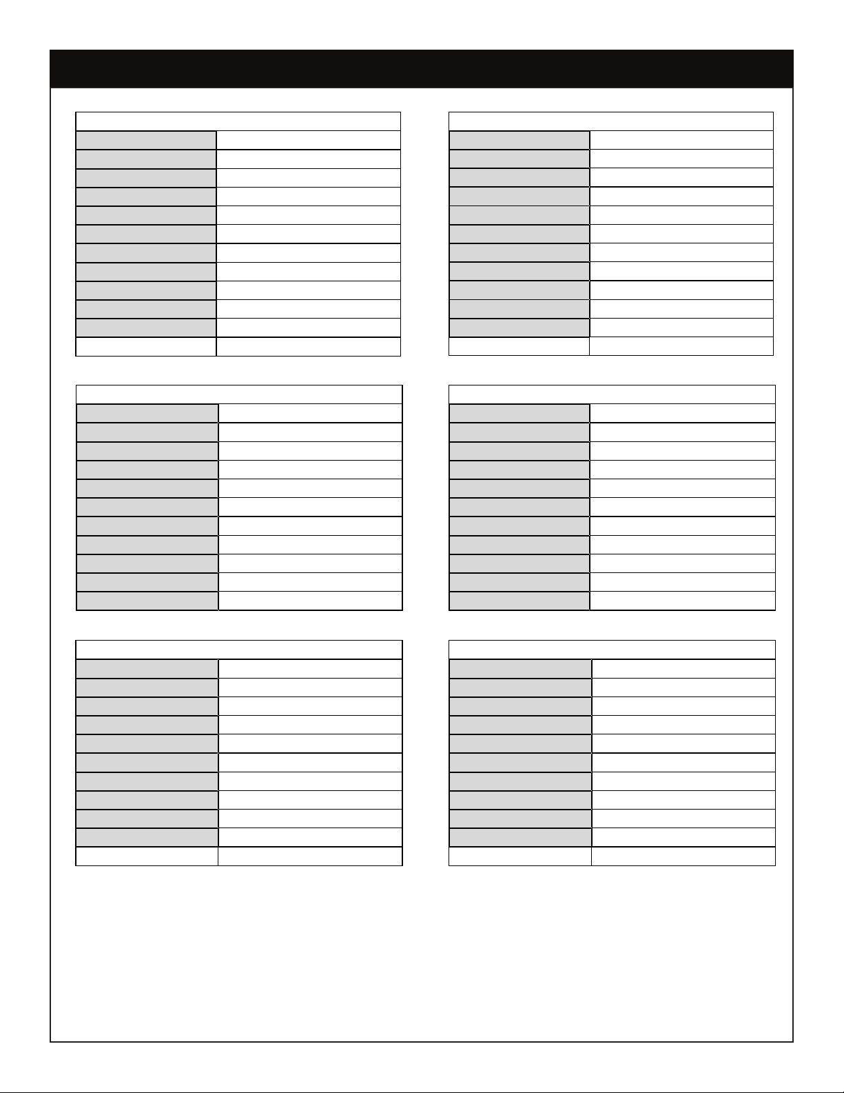
TMAX™30K-9
Applicable Chassis14,000 – 19,500 GVWR
Cab to Axle60” (152.4 cm)
Body Length109” (276.9 cm)
Body Height (Steel)44”/60” (111.76/152.4 cm)
Body Height (AL)52” (132.08 cm)
Body Width94” (238.76 cm)
Compartment Depth22” (55.88 cm)
Floor Width50” (127 cm)
Net Weight (Steel)2,610 lbs (1184 kg)
Net Weight (AL)2,220 lbs (1007 kg)
Crane ModelsEC3200, EC4000, EC5000
3315, 4421, 5521
TMAX™30K-11
Applicable Chassis14,000 – 19,500 GVWR
Cab to Axle84” (213.36 cm)
Body Length133” (337.82 cm)
Body Height (Steel)44”/60" (111.76/152.4 cm)
Body Height (AL)52" (132.08 cm)
Body Width94” (238.76 cm)
Compartment Depth22” (55.88 cm)
Floor Width50” (127 cm)
Net Weight (Steel)2,710 lbs (1229 kg)
Net Weight (AL)2,250 lbs (1021 kg)
Crane ModelsEC3200, EC4000, EC5000
3315, 4421, 5521
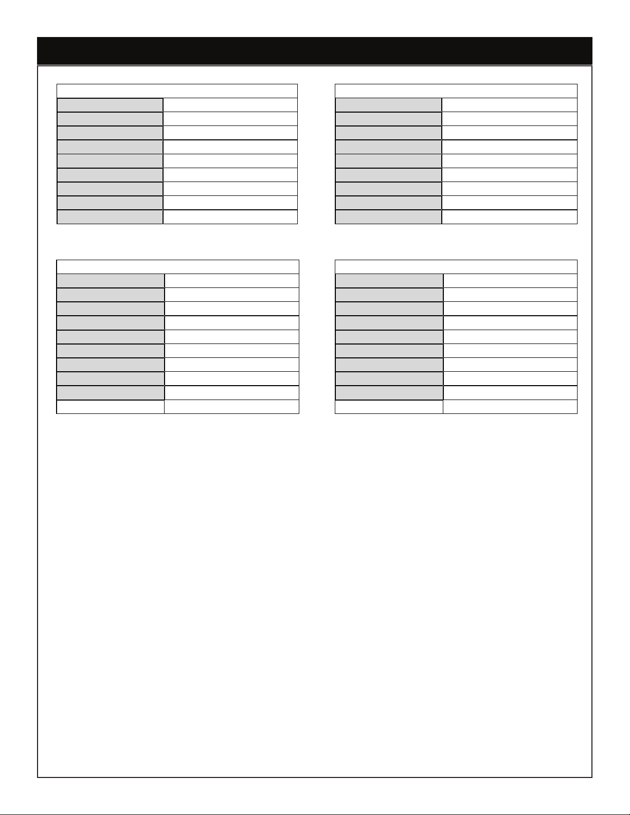
TMAX™1-9
Applicable Chassis16,000 – 19,500 GVWR
Cab to Axle60” (152.4 cm)
Body Length109" (276.86 cm)
Body Height (Steel)44”/60" (111.76/152.4 cm)
Body Height (AL)52" (132.08 cm)
Body Width94” (238.76 cm)
Compartment Depth22” (55.88 cm)
Floor Width50” (127 cm)
Net Weight (Steel)3,285 lbs (1490 kg)
Net Weight (AL)2,750 lbs (1247 kg)
Crane Models3315, 4421, 5521, 7621, 7630
TMAX™1-11
Applicable Chassis16,000 – 19,500 GVWR
Cab to Axle84” (213.36 cm)
Body Length133” (337.82 cm)
Body Height (Steel)44”/60" (111.76/152.4 cm)
Body Height (AL)52" (132.08 cm)
Body Width94” (238.76 cm)
Compartment Depth22” (55.88 cm)
Floor Width50” (127 cm)
Net Weight (Steel)3,740 lbs (1696 kg)
Net Weight (AL)3,050 lbs (1383 kg)
Crane Models3315, 4421, 5521, 7621, 7630
TMAX™2-11
Applicable Chassis19,500 GVWR and up
Cab to Axle84" (213.36 cm)
Body Length133" (337.82 cm)
Body Height60” (152.4 cm)
Body Width94" (238.76 cm)
Compartment Depth22” (55.88 cm)
Floor Width50" (127 cm)
Net Weight (Steel)4,465 lbs (2025 kg)
Net Weight (AL)3,510 lbs (1592 kg)
Crane Models7621, 7630, 9621, 9630,
10621, 10630, 12621, 12630
TMAX™2-14
Applicable Chassis19,500 GVWR and up
Cab to Axle120" (304.8 cm)
Body Length169" (429.26 cm)
Body Height60” (152.4 cm)
Body Width94" (238.76 cm)
Compartment Depth22” (55.88 cm)
Floor Width50" (127 cm)
Net Weight (Steel)4,985 lbs (2261 kg)
Net Weight (AL)3,780 lbs (1715 kg)
Crane Models7621, 7630, 9621, 9630,
10621, 10630, 12621, 12630