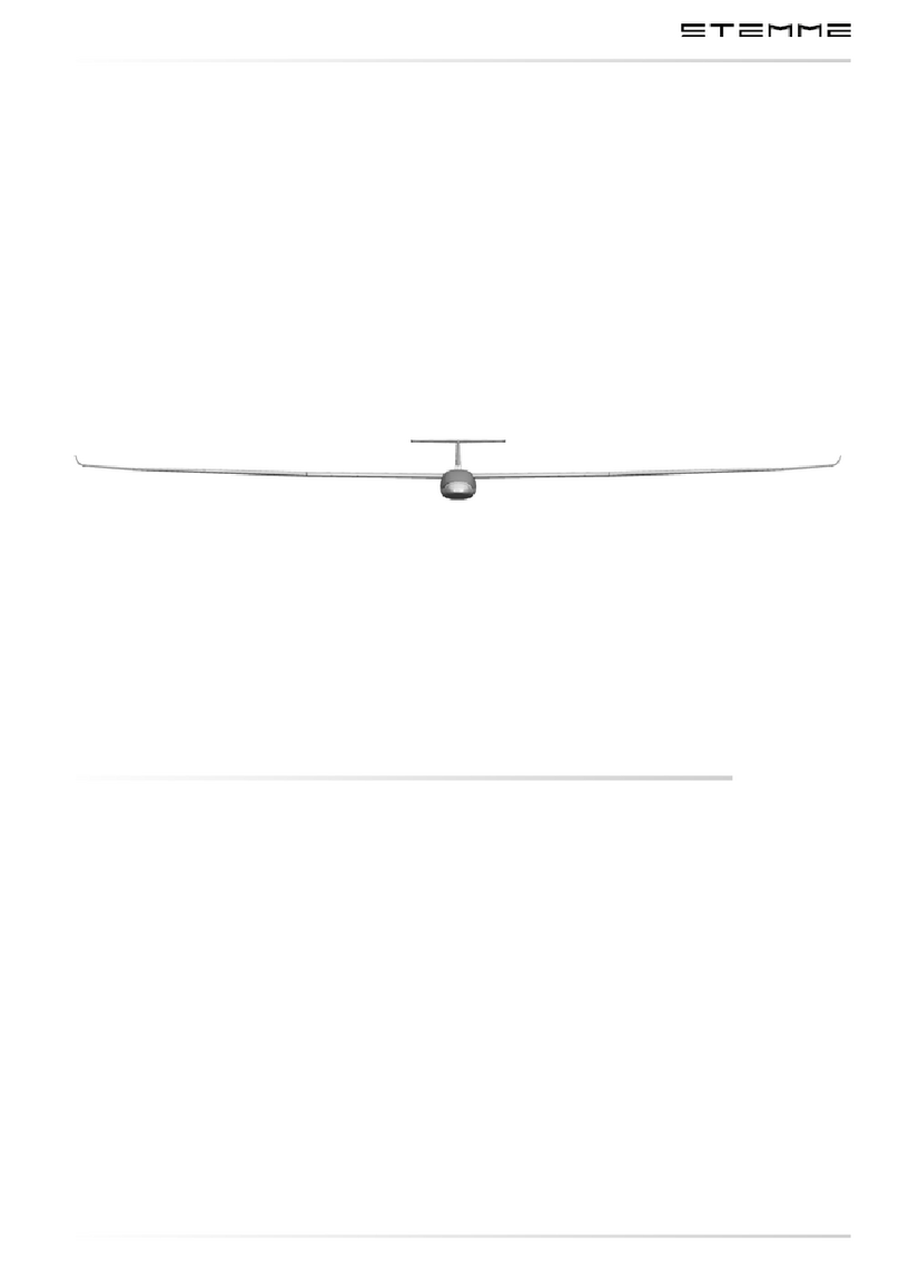
STEMME S10 User manual

Stemme AG – Flugplatzstrasse F2 Nr. 7 – D-15344 Strausberg
A4010021_B19.doc
Doc.No.: A40-10-021
MAINTENANCE MANUAL
for the powered sailplane STEMME S 10
Document No. A40-10-021
Date of Issue: October 1, 1990
Translation and conversion of technical data have been done by best knowledge and judgement.
In any case the original version in the German language is authoritative
Model:
STEMME S 10
Serial number:
10-
Type Certificate: EASA.A.054 (former LBA 846) Registration:
Non-standard equipment or systems with effect to the contents of this manual, if
installed, are entered in the table on page 1.
Druck-Info: Datei enthält 64 Seiten gesamt

Maintenance Manual STEMME S 10
Date of Issue Oct. 01, 1990 page: 1
Amendment No.: 3 Date: July 1, 1993
A4010021_B19.doc-1/27.01.14 14:18/27.01.14 14:18
Doc.No.: A40-10-021
Deviations from the Basic Maintenance Manual for the Type:
The aircraft specified below is fitted, in accordance with the entries in the list, with equipment or systems
installed as an alternative to the equipment of the standard version. Resulting additional text has been inclu-
ded in the Maintenance Manual under the specified revision numbers; the text passages relating to the
standard version have been crossed out. The necessary amendments to the text are described in further
detail in the associated LBA approved Service Bulletins.
The procedure of amending the Manual in the case of installation of alternative equipment is described in
further detail in the Service Bulletin A31-10-008 (see Annex B) as well as in Section 9.3.
The licensed inspector certifies by his signature that this Maintenance Manual complies with the data
specified in the following and with the associated aircraft.
Valid for STEMME S10, serial no.:
Affected Component Am.No.
SB-Number Date Approval

Maintenance Manual STEMME S 10
Date of Issue: Oct. 01, 1990 page: 2-1
Amendment No.: 12 Date: Nov 30. 2007
A4010021_B19.doc-2/27.01.14 14:18/27.01.14 14:18
Doc.No.: A40-10-021
0.1 Record of Amendments
Any amendment of the present manual must be recorded in the following table. Exempted are:
• Data relating to the installation of alternative equipment (page 1)
• Data relating to the installation of supplemental or additional equipment (page 51)
• Deletion of inapplicable text passages pursuant to the Service Bulletin A31-10-008.
The list of amendments on this page and the list of effective pages on the next page are assigned to the
serial number. The indicated revision no. in the headline of these pages does not change with later entries
in the lists.
Information as to which amendments must be included in the present Manual can be seen from the current
"Record of Airworthiness Directives and Service Bulletins" (see Annex B, doc. no. A08-10-000).
The new or amended text of the latest amendment will be marked on the revised page by a black vertical line
on the right hand margin. Any Amendment Numbers applied to the specific page and the date of the most
recent amendment is indicated on the right hand side in the headline of each page. In text passages
concerned by the installation of alternative equipment, the text for both versions is included in [ ]; the text not
applicable to the serial number concerned must be crossed out. For further information please refer to
Section 9.3 or to the Service Bulletin A31-10-008.
The inspector certifies by his signature at the same time the correct transfer of the information specific to the
serial number (deletion of inapplicable text passages).
Am.
No.
Affected
Sections removed Pages included Pages Amendment
Date Date of
inclusion Signature
1 0, 4 4, 21 4, 21 Aug. 15, 1991 Aug. 15, 1991
2 0, 4 4, 21, 22 4, 21, 22 March 1, 1993 March 1, 1993
3 0, 9, 10, 11, 12,
13 1, 2, 3, 5, 51, 53,
54, 55, 56 Title p., 1, 2, 3, 5,
51, 53 to 56,
Cover p. Annex A,
B, and C
July 1, 1993 July 1, 1993
4 3, 12 14, 15, 47*,
Fig. 3.3.2.a
*
,
Fig. 3.6.b
*
14, 15, 47*,
Fig. 3.3.2.a
*,
Fig. 3.6.b
*
May 26, 1993 May 26, 1993
5 not issued
6 3, 4, 10, 12 13, 25, 55,
Fig. 3.2.b 13, 25, 55,
Fig. 3.2.b Feb. 10, 1994 Feb. 10, 1994
7 3, 5, 12 4, 13, 14, 24
···
26,
Fig. 3.2.a
···
g,
Fig. 6.4.1.a
4, 13, 14, 24
···
26,
Fig. 3.2.a
···
g,
Fig. 6.4.1.a
Dec. 05, 1994 Dec. 05, 1994
8 0, 5 2
···
5, 26
···
29 2
···
5, 26
···
29 Aug. 8, 1996 Aug. 8, 1996
9 3, 5, 6, 7, 8 2...5, 19 ,27, 28, 33,
42, 44, 45, 48 2...5, 19 ,27, 28, 33,
42, 44, 45, 48 April 19, 1999 April 19, 1999
10 0,4 2, 3, 21, 22, 2, 3, 21, 22-1, 22-2 March 16, 2005
11 0, 3, 4, 5, 7,9 2..5, 18, 21, 22-1,
22-2, 27, 28, 29, 30,
36, 38, 51..54
2..5, 18, 21, 22-1,
22-2, 27, 28, 29, 30,
36, 38, 51...53, 54-
1, 54-2
May 25, 2005
* These pages may only be incorporated with the quoted amendment number if the alternative equipment
item requiring the amendment is installed in the individual aircraft - please check the entries on page 1 for
the corresponding SB. Amendment no. 4 is mandatory for U.S.A.

Maintenance Manual STEMME S 10 Date of Issue: Oct. 01, 1990 page: 2-2
Amendment No.: 19 Date: Jan. 10, 2014
A4010021_B19.doc- /27.01.14 14:18/27.11.17 1 :51 Doc.No.: A40-10-021
Am.
No.
Affected
Sections removed Pages included Pages Amendment
Date
Date of
inclusion Signature
12 0, 4, 7, 12 Titel, 2 , , 21, 22-1,
22-2, 8, fig. 6. .a,
Titel, 2-1, 2-2 , ,
21, 22-1, 22-2, 8,
fig. 6. .a-1,
fig. 6. .a-2
Nov. 0, 2007
1 0, 4 2 , , 21, 22-1, 22-2 2 , , 21, 22-1, 22-2 Nov. 24, 2008
14 0, 4 2-2, , 21, 22-1,
22-2
2-2, , 21, 22-1,
22-2
Feb. 24, 2010
15 0, 5 2-2, , 2 -29 2-2, , 2 -29 June 07, 2011
16 0, 4 2-2, , 21, 22-1,
22-2
2-2, , 21, 22-1,
22-2
April 04, 2012
17 0, 4 2-2, , 21, 22-1,
22-2
2-2, , 21, 22-1,
22-2
Aug. 1 , 2012
18 0, 4, 5 2-2, , 4, 5, 21,
22-1, 22-2, 2 … 0
2-2, , 4, 5, 21, 22,
2 … 0
Oct. 15, 2012
19 0, , 7, 9 2-2, , 17, 40, 51,
52, 5 , 54-1
2-2, , 17, 40-1,
40-2, 51, 52, 5 ,
54-1
Jan. 10, 2014

Maintenance Manual STEMME S 10 Date of Issue: Oct. 01, 1990 page: 3
Amendment No.: 19 Date: Jan. 10, 2014
A4010021_B19.doc 3/27.01.14 14:18/27.11.17 13:49 Doc.No.: A40 10 021
0.2 List of effective pages
This record is valid only for the Serial No. specified on the title page. Any amendment is contained ex works
that is effective for this Maintenance Manual at Aug. 08, 1996 (amendment status 08). Related to alternative
equipment, only those amendments is provided for that correspond to the entries on page 1, amendments
that are included later must be entered by hand.
Section Page
Am.
No.
Date
Title
12
Nov 30. 2007
1 3 July 1. 1993
0.1 2 1 12
Nov 30. 2007
0.1 2 2 19
Jan. 10, 2014
0.2 3 19
Jan. 10, 2014
0.3 4 18
Oct. 15, 2012
0.3 5 18
Oct. 15, 2012
res. 6 Oct 1. 1990
1 7 Oct 1. 1990
res. 8 Oct 1. 1990
2 9 Oct 1. 1990
2 10 Oct 1. 1990
res. 11 Oct 1. 1990
3.1 12 Oct 1. 1990
3.1/3.2 13 6, 7
Dec 05. 1994
3.3 14 4, 7
Dec 05. 1994
3.3 15 4 May 26. 1993
3.3 16 Oct 1. 1990
3.4 17 19
Jan. 10, 2014
3.5/3.6 18 11
May 25. 2005
3.7/3.8 19 9 April 19. 1999
res. 20 Oct 1. 1990
4 21 18
Oct. 15, 2012
4 22 18
Oct. 15, 2012
5.1/5.2/
5.3
23 18
Oct. 15, 2012
5.3 24 18
Oct. 15, 2012
5.3 25 18
Oct. 15, 2012
5.3 26 18
Oct. 15, 2012
5.3 27 18
Oct. 15, 2012
5.3 28 18
Oct. 15, 2012
Section Page
Am.
No.
Date
5.3 29 18
Oct. 15, 2012
5.4 30 18
Oct. 15, 2012
6.1/6.3 31 Oct 1. 1990
6.4/6.5 32 Oct 1. 1990
6.6 33 9 April 19. 1999
res. 34 Oct 1. 1990
7.1/7.3 35 Oct 1. 1990
7.3 36 11
May 25. 2005
7.3 37 Oct 1. 1990
7.3/7.4 38 12
Nov 30. 2007
7.4 39 Oct 1. 1990
7.4 40 1
19
Jan. 10, 2014
7.4 40 2
19
Jan. 10, 2014
7.4/7.6 41 Oct 1. 1990
7.7/7.8 42 9 April 19. 1999
res. 43 Oct 1. 1990
8 44 9 April 19. 1999
8 45 9 April 19. 1999
8 46 Oct 1. 1990
8 47 Oct 1. 1990
8 48 9 Apr 19. 1999
8 49 Oct 1. 1990
res. 50 Oct 1. 1990
9.1 51 19
Jan. 10, 2014
9.2, 9.3
52 19
Jan. 10, 2014
9.3 53 19
Jan. 10, 2014
9.3 54 1
19
Jan. 10, 2014
9.3 54 2
11
May 25. 2005
10, 11 55 3, 6
Feb10. 1994
12 56 3 July 1. 1993
Figure to
Section
Am.
No.
Am. Date
2.a Oct 1. 1990
3.2.a 7 Dec 05. 1994
3.2.b 7 Dec 05. 1994
3.2.c 7 Dec 05. 1994
3.2.d 7 Dec 05. 1994
3.2.e 7 Dec 05. 1994
3.2.f 7 Dec 05. 1994
3.2.g 7 Dec 05. 1994
3.3.a Oct 1. 1990
3.3.2.a Oct 1. 1990
3.4.1.a Oct 1. 1990
3.5.a Oct 1. 1990
3.6.a Oct 1. 1990
3.6.b Oct 1. 1990
3.6.c Oct 1. 1990
3.6.d Oct 1. 1990
3.6.e Oct 1. 1990
6.3.a 1 12
Nov 30. 2007
6.3.a 2 12
Nov 30. 2007
6.3.b Oct 1. 1990
6.4.1.a 7 Dec. 05. 1994
6.4.2.a Oct 1. 1990
7.4.1.a Oct 1. 1990
Annex A
(Cover Page)
3
July 1. 1993
Annex B
(Cover Page)
3
July 1. 1993
Annex C
(Cover Page)
3
July 1. 1993

Maintenance Manual STEMME S 10
Date of Issue: Oct. 01, 1990 page: 4
Amendment No.: 18 Date: Oct 15, 2012
A4010021_B19.doc-4/27.01.14 14:18/27.01.14 14:18
Doc.No.: A40-10-021
0.3 Contents
0.1 Record of Amendments 2
0.2 List of effective pages 3
0.3 Contents 4
1. General Remarks on Maintenance 7
2. Brief Description and Technical Data 9
3. Description of Assemblies 12
3.1 Cell, Primary and Secondary Structures 12
3.1.1 Wing 12
3.1.2 Fuselage and Cockpit 12
3.1.3 Tail Unit 13
3.2 Control System 13
3.3 Power Plant (figure 3.3.a) 14
3.3.1 Engine 14
3.3.2 Fuel system 14
3.3.3 Oil System 15
3.3.4 Cooling System 15
3.3.5 Induction System 15
3.3.6 Exhaust System 15
3.3.7 Power-Plant Controls and Instruments 16
3.3.8 Fire Protection 16
3.3.9 Engine Cowlings 16
3.3.10 Propeller 16
3.3.11 Drive train System 16
3.4 Landing Gear 17
3.4.1 Main Landing Gear (figure 3.4.1.a) 17
3.4.2 Tail Wheel 18
3.5 Flight Instruments, Pressure System (figure 3.5.a) 18
3.6 Electric System (figures 3.6.a to 3.6.e) 18
3.7 Communication and Navigation Equipment 19
3.8 Oxygen Equipment 19
4. Airworthiness Limitations Section 21
5. Time Limits / Maintenance Checks 23
5.1 Life-Limited Components 23
5.2 Pre-Flight Checks 23
5.3 Periodical Checks, Inspection Lists 23
5.3.1 Wing 24
5.3.2 Fuselage Front Section 24
5.3.3 Cockpit 25
5.3.4 Centre Section of Fuselage 25
5.3.5 Tail Boom 26
5.3.6 Empennage 26
5.3.7 Powerplant - except Propeller and Drivetrain System 27
5.3.8 Propeller 27
5.3.9 Drivetrain System 27
5.3.10 Main Landing Gear 28
5.3.11 Tail Wheel 28
5.3.12 Flight Instruments and Static Pressure System 28
5.3.13 Electrical System 29
5.3.14 Radio and Navigation Equipment 29
5.3.15 Oxygen System 29
5.3.16 Completition works 29
5.4 Special Inspections 30

Maintenance Manual STEMME S 10
Date of Issue: Oct. 01, 1990 page: 5
Amendment No.: 18 Date: Oct 15, 2012
A4010021_B19.doc-5/27.01.14 14:18/27.01.14 14:18
Doc.No.: A40-10-021
5.4.1 Inspection following an Impact Landing or a Wing Tip Landing 30
5.4.2 Inspection following an Impact to the rotating Propeller 30
6. Maintenance Instructions, Tolerances, Adjustment Data for the Aircraft 31
6.1 General Information 31
6.2 Ground Towing, Supporting Points, and Lifting of Aircraft 31
6.3 Determination of the Empty Mass and Corresponding Center of Gravity; Information on Mass
Limits 31
6.4 Control System 32
6.4.1 Deflection of Control Surfaces, Control System Friction, and Pilot Forces 32
6.4.2 Masses and Moments of the Control Surfaces 32
6.4.3 Slackness of Control System Bearings 32
6.5 Lubrication Chart 32
6.6 Tightening Moments for Screw Joints 33
7. Maintenance Instructions, Tolerances, Adjustment Data for Assemblies /
Equipment 35
7.1 Airframe 35
7.1.1 Wing 35
7.1.2 Fuselage and Cockpit 35
7.1.3 Tail Units 35
7.2 Control System 35
7.3 Powerplant 35
7.3.1 Engine 35
7.3.2 Fuel System 36
7.3.3 Oil System 36
7.3.4 Cooling System 36
7.3.5 Induction System 36
7.3.6 Controls/Instruments 37
7.3.7 Fire Protection 37
7.3.8 Engine Cowlings 37
7.3.9 Propeller 37
7.3.10 Drivetrain System 38
7.4 Landing Gear 38
7.4.1 Main Landing Gear 38
7.4.2 Tail Wheel 41
7.5 Flight Instruments and Static Pressure System 41
7.6 Electrical System 41
7.7 Radio and Navigation Equipment 42
7.8 Oxygen Equipment 42
8. List of cockpit placards and their position 44
9. Equipment 51
9.1 Minimum Equipment List 51
9.2 Supplemental Equipment 52
9.3 Additional Equipment and Systems 52
9.3.1 Alternative Equipment 52
9.3.2 Additional Equipment 53
9.3.2 Optional Systems 54-2
10. List of Special Tools 55
11. List of Maintenance Documents for Parts being approved independently from
the Aircraft 55
12. Figures referring to the previous Sections 56
Annex A - Supplemental Instructions for Maintenance and Care, Maintenance Instructions -
Annex B - Service Bulletins, Airworthiness Directives -
Annex C - Documents (Inspection and Operations Documents)-

Maintenance Manual STEMME S 10
Date of Issue: Oct. 01, 1990 page: 6
Amendment No.: Date: -
A4010021_B19.doc
Doc.No.: A40-10-021
intentionally left blank

Maintenance Manual STEMME S10
Date of Issue: Oct. 01, 1990 Page 7
Amendment No.: Date: -
A4010021_B19.doc
Doc.No.: A40-10-021
1. General Remarks on Maintenance
The holder of the powered glider STEMME S10 is obliged to ensure that, according to the specific national
laws and regulations, the maintenance of the aircraft follows the instructions of this manual. Among others,
there are
−controls,
−adjustments,
−exchange of fluids and lubricants,
−exchange of parts going to expire their service life,
−small repairs.
All maintenance work must be documented.
The manufacturer is to be notified immediately if the ownership changes and the message must be confirmed
by the manufacturer, so that all information for continued airworthiness can be given to the holder.
For maintenance work the following documents must especially paid attention to:
1. This Maintenance Manual for the powered glider STEMME S10,
2. The "Flight Manual for the motorglider STEMME S10",
3. The "Operating and Maintenance Manual Limbach L2400 and Series",
4. Maintenance instructions for the "L'Hotellier" ball and swivel joints (in Appendix to this Maintenance
Manual),
5. Manufacturer's documents referring to the equipment listed in the equipment list of the corresponding S/N.
The amount of maintenance work depends, irrespective of the periodic checks, on the utilisation of the
aircraft, the climate, airfield conditions, storing facilities and other factors. E. g., in sandy environs it might be
necessary to clean all filters before every commencement of operation; on the other hand in coastal or rainy
regions it is important to take more care of the conservation of the aircraft. The instructions in this manual are
valid under normal conditions and use.
Use only spare parts from the manufacturer or according to his requirements.
By faults which affect the airworthiness the manufacturer must be informed immediately.
The maintenance must be carried out by qualified personnel.

Maintenance Manual STEMME S10
Date of Issue: Oct. 01, 1990 Page 8
Amendment No.: Date: --
A4010021_B19.doc
Doc.No.: A40-10-021
intentionally left blank

Maintenance Manual STEMME S10
Date of Issue: Oct. 01, 1990 Page 9
Amendment No.: Date: --
A4010021_B19.doc
Doc.No.: A40-10-021
2. Brief Description and Technical Data
The STEMME S10 is a twin-seat high performance powered sailplane with an innovative propulsion concept
and a high grade aerodynamic design. The wing is made of carbon fibre reinforced plastic, the fuselage is
fabricated as a hybrid construction (carbon, aramide, glass) with an extremely rigid steel tube framework in
the centre of force introduction. The seats are arranged side by side and equipped with dual controls.
The wing is attached to the fuselage behind the cockpit in the fuselage upper third. The wing consists of a
one-part central wing equipped with flaps and Schempp-Hirth air brakes as well as two outboard wings with
continuous ailerons.
The tail unit is designed as a T-tail.
The two-leg landing gear is electrically extended and retracted and is equipped with hydraulic disc brakes.
The tail wheel is steered with the pedals.
The engine is located in the fuselage in a central steel tube framework near the aeroplane centre of gravity.
The engine power is transmitted via a composite material shaft and a transmission gear to an articulated
propeller in the fuselage nose. In soaring flight, the propeller is folded and covered by the slidable fuselage
nose cone (propeller dome).
One fuel tank is located in each outboard area of the central wing.
Technical Data (general drawing figure 2.a)
Wing
wing span 23.00 m
central wing span 9.90 m
wing area 18.74 m²
aspect ratio 28.22
dihedral angle 0.75°
sweep of central wing leading edge 0°
sweep of outboard wing leading edge up to the bend 0°
airfoil: laminar profile HQ41/14.35
Air Brakes (two-storied Schempp-Hirth air brakes on wing upper side only)
length 1.50 m
area 0.22 m²
maximum height above wing upper side 0.16 m
Wing Flaps
span 4.39 m
area 0.75 m²
flap positions: - 10°
- 5°
0°
+ 5°
+ 10°
(L) + 16°
Ailerons
span 5.80 m
area 0.68 m²

Maintenance Manual STEMME S10
Date of Issue: Oct. 01, 1990 Page 10
Amendment No.: Date: --
A4010021_B19.doc
Doc.No.: A40-10-021
Fuselage
length 8.42 m
width 1.18 m
clear cockpit width 1.16 m
clear cockpit height 0.93 m
height at tail unit 1.75 m
Vertical Tail
height 1.60 m
total area 1.51 m²
area of rudder 0.52 m²
airfoil FX 71-L-150/35
Horizontal Tail
span 3.10 m
total area 1.46 m²
area of elevator 0.36 m²
aspect ratio 0.62
airfoil FX 71-L-150/25
Landing Gear
2 main wheels (disc brake) 348 x 122
wheel track 1.15 m
tail wheel (steerable) 210 x 65
wheel base 5.46 m
Power-Plant
engine Limbach L 2400 EB 1.D
take-off power (3400 rpm) 69 kW
propeller STEMME 10 AP-N
diameter 1.61 m
gear transmission ratio i=1.18
Masses (see also figure 14.3.a)
maximum allowable mass 850 kg
empty mass 640 kg
maximum mass of non-structural parts 570 kg
total useful load (occupants, fuel, baggage) 210 kg
mass of ballast: For pilot masses between 55 and 70 kg (including parachute), the defined ballast mass of 6
kg must be attached to the right-hand rudder pedal support.
For distribution of the useful load, please refer to the load and balance sheet in the Flight Manual.
The empty mass stated does not include any additional equipment. The total useful load will be reduced
depending on the equipment.
In-flight Centre-of-Gravity Range aft of datum
(formed by the central wing leading edge, see figure 6.3.a) 254 to 420 mm
For further technical data, please refer to the Flight Manual.

Maintenance Manual STEMME S10
Date of Issue: Oct. 01, 1990 Page 11
Amendment No.: Date: --
A4010021_B19.doc
Doc.No.: A40-10-021
intentionally left blank

Maintenance Manual STEMME S10
Date of Issue: Oct. 01, 1990 Page 12
Amendment No.: Date: --
A4010021_B19.doc
Doc.No.: A40-10-021
3. Description of Assemblies
3.1 Cell, Primary and Secondary Structures
The primary structure includes:
- wing spars, root ribs, and wing spar boxes
- wing shells
- central fuselage framework
- tail boom and vertical stabiliser
- front portion of fuselage
- horizontal stabiliser
- fittings
The secondary structure includes
- control surfaces
- cowlings, cooling air system ducts, cockpit components
3.1.1 Wing
Sandwich shell made of carbon fibre reinforced plastic (CFP), CFP spars.
Consisting of three sections i.e. central wing with a span of 32.5 ft. (9.90 m) and two outboard wing sections
with a length of 21.5 ft. (6.55 m) each.
Attachment to the fuselage by means of four sliding bolts, attachment central wing to outboard wings with one
sliding bolt each.
Removable cowling to cover the wing/fuselage attachment. Beneath the cowling, free access to the wing
attachment, control system joints and the "mixed" aileron/flap controls. Detachment of wing from the fuselage
upwards.
Flaps over the total span of the central wing, ailerons over the total span of outboard wings. Articulation of
flaps and ailerons on the lower side. Symmetrical and asymmetrical cross connection of flap and aileron
controls.
Two-storied Schempp-Hirth air brakes on wing upper side.
Slots of flaps and ailerons sealed with elastic adhesive tape on wing upper side and with textile tape on lower
side.
Boundary layer turbulator (adhesive point tape) on the wing lower side for defined flow transition (special
equipment).
3.1.2 Fuselage and Cockpit
Modular construction of three assemblies bolted to each other: front section of fuselage (CFP-armada-glass
construction), central fuselage framework with cowlings, tail boom (CFP construction).
The loads from the fuselage front section, wing, landing gear, power-plant and tail unit are introduced into the
central fuselage framework.
Cockpit: Two seats arranged side by side. Console between the seats. Seat backs adjustable step by step,
dual controls.

Maintenance Manual STEMME S10 Edition: Oct. 01, 1990 Page 13
Amendment: 6, 7 Date: Dec. 05, 1994
A4010021_B19.doc Doc.No.: A40 10 021
One piece canopy hinged at the front and held in opened position by gas springs. Three locks each on the
left and the right side to be operated by one locking lever on each side; "Röger" hook on the rear/top.
Emergency jettisoning: Open both locking levers and pull T shaped handle for emergency opening (red, on
the instrument panel). The canopy hinge opens and the canopy is lifted by means of a gas spring by
approximately 4 in. (100 mm). The Röger hook must remain closed, since it is the axis of rotation until the
canopy is jettisoned.
Cockpit ventilation via a nozzle in the instrument panel, canopy ventilation via openings in the canopy frame.
Instrument panel comprising three faces.
Two four point harnesses with central locks.
Cockpit heating with power plant waste heat (special equipment).
3.1.3 Tail Unit
Horizontal Tail
T arrangement.
stabiliser as sandwich construction of CFP, elevator made of CFP.
elevator slot sealed by elastic tape.
Vertical Tail
Stabiliser as a sandwich construction of CFP.
rudder as a sandwich construction of GFP, rudder slot sealed by elastic tape.
integrated COM antenna in the rudder.
3.2 Control System
Longitudinal Control (figure 3.2.a)
Both control sticks are coupled by a connection tube. The control movements are transmitted via push pull
rods to the end of the tail boom and then straight up to the elevator fitting. In the tail boom, the push pull rod
is several times supported by linear motion ball bearings. The (adjustable) longitudinal control stops are in the
middle of the connection tube beneath the right control system cover in the cockpit.
Longitudinal Trim (figure 3.2.a)
The powered sailplane is trimmed by means of a slidable spring system acting upon the connection tube of
the longitudinal control in the cockpit.
ing Flap Control System (figures 3.2.b and 3.2.c)
Both flap control levers are coupled by a connection tube. Control inputs are transmitted from this connection
tube via push pull rods to a "mixing shaft" in the central fuselage. From this "mixing shaft", the control inputs
are transmitted via bell crank levers, push pull rods and quick release joints to the control rods in the wing.
The control rods in the wing are supported by means of linear motion ball bearings. Via bell crank levers, the
control movement is transmitted to the flap drive fittings.
On the flap input of the mixer, the flap control system is supported against the airframe structure by means of
a gas spring so that the operation lever is nearly free of forces in each position corresponding to the
respective airspeed. Due to the bi directional viscous damping of the gas spring, impact loads are introduced
into the structure and thus are held off the hand lever and the locking appliance. Flap positions are set in a
notched plate that locks the control lever at the connection tube, located below the control gap cover in the
cockpit.

Maintenance Manual STEMME S10
Date of Issue Oct. 1, 1990 page: 14
Amendment No.: 4, 7 Date: Dec. 05, 1994
A4010021_B19.doc
Doc.No.: A40-10-021
Lateral Control (figures 3.2.d and 3.2.e)
The control sticks are cross-connected beneath the connection tube of the longitudinal control to a bell-crank
lever in the centre. From the bell-crank lever, the control input is transmitted via push-pull rods to the "mixing
shaft" in the central fuselage. Via this "mixing shaft", bell-crank levers, push-pull rods and quick-release
joints, the control rods in the wing are moved. Both sides of the central wing contain a straight-through control
rod supported by several linear motion ball bearings and equipped with a further quick-release joint at the
attachment of the central wing to the outboard wings. From the push-pull rods in the outboard wing, the
control movement is transmitted via two bell-crank levers to the drive fittings of the ailerons.
By means of the "mixing shaft", the ailerons are moved together with flap position changes and the flaps are
moved together with aileron deflections. The percentage of co-movement depends on the position of the
control surfaces. The lateral control stops (adjustment screws) are located in the cockpit beneath the covers
of the control system well, on the elevator connection tube at the left and right side .
Operation of Air Brakes (figures 3.2.f and 3.2.g)
The hand-levers to operate the air brakes are coupled by means of a connection tube. Travel of the levers is
transmitted via push-pull rods and bell-crank levers to a driving lever (elbow lever) in the centre fuselage,
from which it is transmitted via push-pull rods and quick-release joints to push-pull rods in the wing, which
then move the air brakes. The push-pull rods in the wing are supported by linear motion ball bearings.
The fully retracted position of the airbrakes is barred by over-centre-locking of the elbow lever. The locked
position can be adjusted by a stop screw at the elbow lever. The fully extended position is determined by a fix
rubber stop, which one end of the driving lever butts upon when this position is reached.
Directional Control
From the left and the right rudder pedal support, the control cables are led through the central fuselage to the
tail boom entrance. At this point, the control cables of the left pedals and the right pedals meet to be directed
further to the rudder driving lever. From the rudder driving lever, the tail wheel is steered via a spring
connection. The directional control stops are mounted on the lower rudder support, the pertinent adjustment
screws are located at the rudder on the drive fitting.
3.3 Power Plant
(figure 3.3.a)
3.3.1 Engine
Type: Limbach L 2400 EB1.AD
1
Engine Description: please refer to Flight Engine Operating and Maintenance Manual "Limbach
L 2400 and Series"
Forward Engine Mount: by means of a separate steel tube beam in vibration absorbing elements in the
forward lateral framework junctions
Rear Engine Mount: at the rear engine flange on top by means of two vibration absorbing elements on
the upper transversal tube of the framework.
3.3.2 Fuel system
The powered sailplane is equipped with two independent fuel systems connected to each other only beyond
the fuel pumps and each supplying fuel to both carburettors in parallel. Each system comprises a fuel shut-off
valve, a water trap, a coarse filter and a fine filter. A backup system consists of two electrically driven fuel
pumps, each piped in parallel to the respective main pump, both backup pumps switched with one common
switch. General view: figures 3.3.2.a (piping) and 3.6.b (wiring).
1
Type designation changed: formerly L 2400 EB1.D. Ref. to Limbach Service Bulletin no. 17

Maintenance Manual STEMME S10
Date of Issue Oct. 01, 1990 page: 15
Amendment No.: 4 Date: May 26, 1993
A4010021_B19.doc
Doc.No.: A40-10-021
One fuel tank is installed in each outboard area of the central wing between spar and leading edge. The fuel
tanks are made of a hybrid laminate. To ensure long-time resistance, the internal surfaces of the tanks are
coated with a fuel-resistant protection film "Scotch Clad 776" (3M Company; MIL-D-1795-B).
The fuel is supplied from the tank through a pipe of relatively large cross section to the central wing root. At
this point, a finger strainer combined with a flexible hose fitting is installed. From this flexible hose fitting, the
fuel line - equipped with a fine filter - is conducted to the water separator. A flexible hose of 0.4 in. (10 mm)
internal diameter leading to the drainer in the wheel well serves as a water trap. The fuel line is directed from
the water separator via the associated shut-off valve to the fuel pumps. Beyond those, both systems are
cross-connected and then piped on to the distribution line of the carburettors. The main pump of the left hand
fuel system is mechanically driven from the engine (and located on it), the right hand system is provided with
an electrically driven main pump.
The fuel tank vent is located close to the filler cap. From this point, an aluminium tube Ø 8 x 1 mm is installed
over a length of 5.25 ft. (1.60 m) towards the fuselage and then back to the wing attachment point. The fuel
tank vent discharges on the wing lower side at the attachment. The discharge opening is tapered by 45°
towards flight direction (thus ramming intake).
3.3.3 Oil System
A thermostat-controlled oil cooler (switching point 176°F / 80°C) is installed in the main oil flow of the engine.
The oil cooler is located on the left side of the central fuselage framework. The connection to the fittings on
the engine is realised by means of flexible hoses with metal reinforcement and a fire-resistant sheathing.
3.3.4 Cooling System
The engine is cooled by ram air. The air inlets are to the left and to the right side of the central fuselage
cowlings. From these inlets, the cooling air flows directly to the cylinder heads. A minor portion of the cooling
air is blown into the engine compartment through several openings. On the left side of the central fuselage
cowling, the cooling air duct is continued to the oil cooler. The cooling air outlet is located in the lower cowling
of the central fuselage. Both inlet flaps and the waste air flap are synchronously operated by means of
bowden cables, which are directed into the cockpit and attached to a bell-crank lever in the left leg room
(behind the cover). This bell-crank lever to close the flaps is actuated together with the propeller dome
control. All three flaps are opened by means of springs attached to the flaps, when the propeller dome is
opened and the bell-crank lever released.
3.3.5 Induction System
The screens of the engine induction system are mounted on the firewall. The air is supplied through air inlets
at the upper end of the vertical stabiliser, through the tail boom and air inlets in the front and central areas of
the fuselage. From the induction system screens, the air is supplied through a spiral hose duct to the
carburettors.
3.3.6 Exhaust System
The arrangement of the exhaust system can be seen from the general view figure 3.3.a:
The exhaust manifolds are directed beneath the engine with slight lateral displacement rearwards to a
muffler. Drip pans are installed beneath the carburettors in order to collect possible fuel leakage and to divert
leaking fuel around the exhaust manifold. The exhaust gases discharge from the muffler directly down
through the lower engine cowling.
The whole exhaust system is made of corrosion resistant steel. It is attached exclusively to the engine.

Maintenance Manual STEMME S10
Date of Issue Oct. 01, 1990 page: 16
Amendment No.: Date:
A4010021_B19.doc
Doc.No.: A40-10-021
3.3.7 Power-Plant Controls and Instruments
Power and choke are controlled via bowden cables led from the carburettors over the engine to the central
console in the cockpit. Operation from the cockpit is realised by means of a lever with adjustable friction.
The cowl flaps are moved simultaneously with the lever for opening and closing the propeller dome.
The power-plant instruments are located on the right face of the instrument panel.
3.3.8 Fire Protection
To the front, upwards and rearwards, the engine including the exhaust system and the induction system
(except for induction system screens) is separated by means of a fire-wall from the remaining parts of the
powered sailplane. The firewall is made of corrosion resistant steel sheet of .01 in. (0,38 mm) thickness.
The engine compartment is enclosed at the sides and below by the engine cowlings. The internal surfaces of
the cowlings are treated with a fire protection coating.
3.3.9 Engine Cowlings
The engine cowling is formed by the lateral and the lower parts of the central fuselage cowling. The cowlings
are connected to each other and to the fuselage front section and to the tail boom by means of Camloc snap
fasteners.
3.3.10 Propeller
The articulated propeller consists of a central part and two propeller blades hinged to this central part. The
articulation axle is aligned so that the propeller blades are movable in the plane of rotation of the propeller.
When the propeller is not running, the blades are folded inwards by means of springs.
When the engine is started, the blades unfold automatically by centrifugal force. Soft rubber stops protect the
blades in case of probable overswing. Also during folding, the movement of the blades is cushioned by
rubber stops.
The central part of the propeller is made of high strength aluminium. The propeller blades are made of
carbon/aramide/glass laminate. The blade hinges are equipped with needle bearings.
Marking: - complete propeller: 10 AP-N / XX / YYYY / ZZZZ
- propeller blade: 10 AP-NB / XX / YYYY / ZZZZ
X = date of amendment of drawing
Y = order number of production
Z = month and year of production
3.3.11 Drive train System
The drivetrain includes:
−Clutch on the engine side: a force transmitting clutch operated by direction and speed. In addition, the
clutch has integrated positive elements to allow torsional and angular flexibility as well as longitudinal
flexibility. Since the clutch transmits the torque by friction, it serves as an overload protection at the same
time.

Maintenance Manual STEMME S10
Date of Issue Oct. 01, 1990 page: 17
Amendment No.: 19 Date: Jan. 10, 2014
A4010021_B19.doc
Doc.No.: A40-10-021
−Drive shaft made of carbon fibre reinforced composite material
−Flexible coupling on transmission gear side: flexible coupling with elastic angular and torsional flexibility.
Lateral flexibility is eliminated by means of a centring bearing.
−Transmission unit: one-stage quintuple high performance V-belt transmission unit with maintenance-free
sealed antifriction bearings. The belt pulleys are subjected to a special hard anodising process. The
transmission unit is supported in the foremost fuselage frame by four mounts with non-linear characteristics
for vibration absorption.
3.4 Landing Gear
3.4.1 Main Landing Gear (figure 3.4.1.a)
Left and right landing gear legs each supported by two sleeve bearings in the central fuselage framework,
swivel axis in flight direction. Trailing arms hinged with sleeve bearings in the legs. Elastomere spring bars in
the rear tube of the leg.
Retraction and extension with one electric spindle drive for each side.
Retraction: one after the other - first the left landing gear leg, then the right one together with the gear
door, and then the left gear door.
Extension: first the left gear door, then the right landing gear leg including gear door, and then the left
leg.
The Gear-down position is locked by means of over-centre locking of the operating arms.
Electric stop switches for "DOWN" position: on the associated operating arm.
Electric stop switches for "UP" position: at the front of the wheel well on the associated side.
Indication of "DOWN" position by one green LED (light emitting diode) each for the left and the right gear leg
on the right face of the instrument panel. During extension and re-traction of the landing gear legs, the
corresponding LED is blinking red. With the landing gear in the retracted position, the diodes extinguish and
the position of the spindle drives is fixed by means of blocking brakes above the spindle drive motors. The
brakes are locked by springs and released electrically during operation of the spindle drives.
The wheel well is covered by two landing gear doors; the right-hand door is coupled via a spring element
directly to the right gear leg. The left-hand door is closed via a bowden cable which is operated also by the
right landing gear during the last part of its track.
Electric landing gear warning: acoustic warning activated by switches on the air brakes control shaft beneath
the left stick cover.
The disk brakes on the main L/G wheels are operated hydraulically. The main cylinder for both the left and
right wheel is located on the LH control stick, on RH stick optional. The pressure line from the main brake
cylinder to the brake callipers of the wheel brake in the center fuselage are designed as metal-shielded brake
hoses. The brake fluid reservoir is located in the landing-gear bay, cabin rear wall.
The parking brake valve to set and to release the parking brake is located on the floor panel console in front
of the LH control stick. The parking brake valve is operated by a lever respectively rotary handle.
The brake action is simultaneously on both main wheels. Maximum brake pressure for the system layout is
115 bar / 1668 psi, maximum allowed system pressure is 200 bar / 2900 psi.
Only for hydromechanical Brake System:
The master cylinder for both the left and right wheel is located in the wheel well at the front wall (pressure line
to the wheel cylinders by short metal tube, T-type distributor and metal-shielded brake hoses). The
connection to the hand operating lever on the left stick (right stick optional) is made by a bowden cable,
adjustable at the master cylinder. The hand lever can be locked in the operated position for use as a parking
brake.
Main Landing Gear Emergency Extension
Mechanical emergency extension system: By operating two pulls, the connection of the electric landing gear
spindle drive to the operating arm is successively released via bowden cables. The landing gear legs extend
by gravity to the "DOWN" position. The operating arms are pressed into the locked position by means of
spring clips. For operation, the proper sequence is to be adhered to: first the right gear leg, then the left gear
leg. The right landing gear leg is equipped with a catch strap in order to prevent the legs from getting stuck in
case of incorrect operation (i.e. left leg first).

Maintenance Manual STEMME S10
Date of Issue Oct. 01, 1990 page: 18
Amendment No.: 11 Date: May 25. 2005
A4010021_B19.doc-18/27.01.14 14:18/27.01.14 14:18
Doc.No.: A40-10-021
3.4.2 Tail Wheel
Tail wheel steerable with the rudder pedals and connected to the rudder by springs.
3.5 Flight Instruments, Pressure System
(figure 3.5.a)
Instruments: see Equipment List.
The pitot pressure, the static pressure and the total energy compensation are measured by means of a bar
probe in the propeller dome. The ducts are directed to the instrument panel. The static pressure measured by
the bar probe may not be used for the airspeed indicator!
In addition, static pressure is measured primarily for the airspeed indicating system on both sides of the tail
boom. This duct is also directed to the instrument panel. All ducts are equipped with water traps/filters.
3.6 Electric System
(figures 3.6.a to 3.6.e)
The electric system is supplied by a main battery and a generator. The main battery is installed behind the
firewall.
All current circuits and electric instruments are protected by fuses or circuit breakers, respectively.
Master Switch: cuts all current sources from the main bus. In case of failure of the main current
circuit, the avionics instruments are automatically switched over to the auxiliary
battery (if installed).
Subordinate Switches:
Engine master switch to switch "ON" / "OFF" all electric appliances of the power-plant (starter,
instruments, etc.) connected to the main battery and the generator. Recommended
switch position for soaring flight: "OFF", since otherwise current consumed.
Starter: push button for electric engine starter.
Ignition: to switch Ignition "ON" / "OFF".
Avionics: to switch "ON" / "OFF" all flight and navigation instruments electrically energised.
During operation of the starter, the avionics instruments are switched off or
switched over to the auxiliary battery (if installed).
Landing gear switch: – Upper position: RETRACT
−Lower position: LOWER
−Centre position: Circuit disconnected from electrical system.
ACL (optional): ON / OFF - only operative with engine master switch ON (Anti-Collision Light).
Position lights (optional): ON / OFF - only operative with engine master switch ON.

Other manuals for S10
5
Table of contents
Other STEMME Aircraft manuals

STEMME
STEMME S6 Technical specifications

STEMME
STEMME S6-RT Technical specifications

STEMME
STEMME S12 User manual

STEMME
STEMME S6 Technical specifications

STEMME
STEMME S10 Technical specifications

STEMME
STEMME S10 User manual

STEMME
STEMME S10 User manual

STEMME
STEMME S10 Technical specifications

STEMME
STEMME S10 User manual

STEMME
STEMME TSA-M Technical specifications