9cdvigroup.com
1
2
3
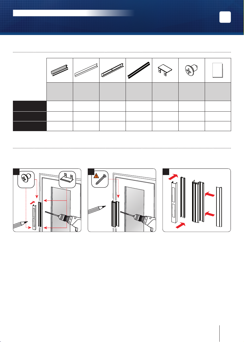
4] MONTAGE
Avantdecommencerlemontage,réunissezlesoutilsnécessaires(Perceuse,visseuse,
mètre,tournevis,vis,chevilles,écrous…),enfonctiondelasurfaced’installation.
Positionnez le support mural avec
ses ventouses sur le xe ou semi
xe. Prenez les marques dans les
trous oblongs horizontaux et verti-
cauxetpercezlasurfaceduvantail
auniveaudesmarques.Prévoyezles
sorties des câbles grâce au bos-
sage central à l’arrière du support
muraletenvousaidantduschéma
de câblage des ventouses (page
suivante). Vissez le support mu-
ral et xez les bouchons à chaque
extrémité du prol à l’aide des vis
auto-taraudeusesàtêtebombéeM4
(fournies).
Positionnez la poignée bandeau
muniedesescontreplaquessurle
vantailouvrant.Prenezlesmarques
dans les trous oblongs horizontaux
et verticaux pour xer la poignée
bandeau. Percer la surface de la
porte au niveau des marques réa-
lisées. Placez et vissez provisoire-
ment la poignée an de laisser
un
léger espace qui vous permettra
d’effectuer le réglage nal de l’en-
semble. Fermez la porte, vériez
que les ventouses sont bien posi-
tionnéesfaceàleurcontreplaques
puisxezdénitivementlapoignée
bandeau.
Pournaliserlemontage,positionnez
le
capot sur le support mural et em-
boitez-ledans son logement. Il est
aussipossibledevisserlecapotpar
ses extrémités à l’aide
de vis auto
-perçeuse
directementsurlesupport
mural.Pourlebandeau,mêmepro-
cédure,installezlecachevisdanssa
charnière et emboitez-le dans son
logement.
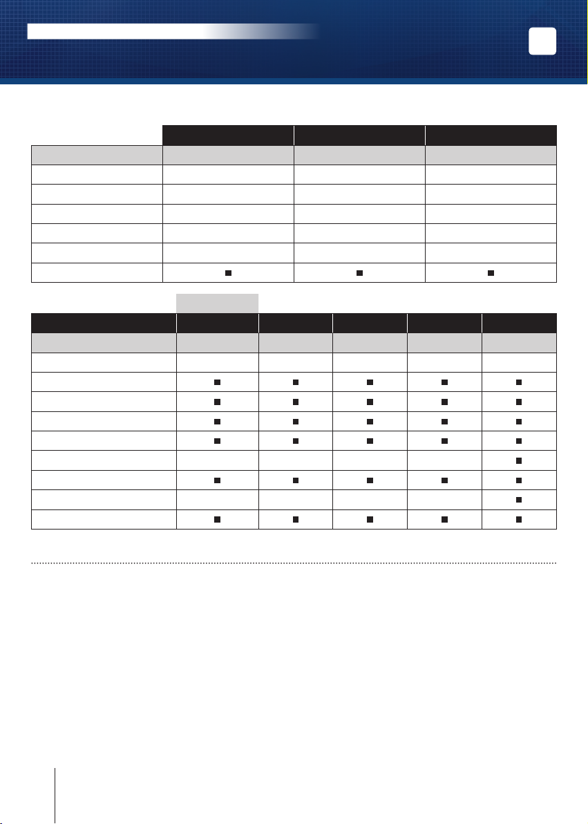
3] ÉLÉMENTS FOURNIS
FR
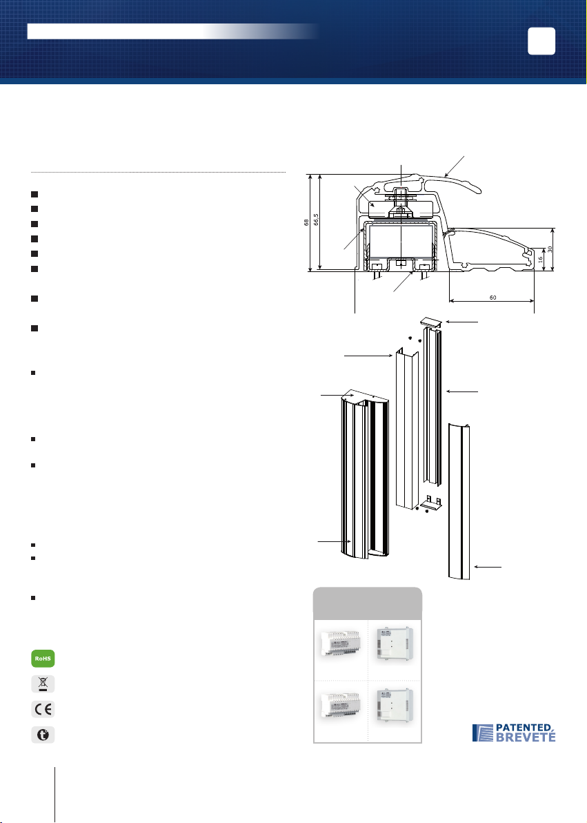
BO800RN
Bandeaux architecturaux et poignées ventouses
MANUEL D’INSTALLATION
Prol
poignée
avec
bouchons
Prol
cache-vis
Capot pour
support
mural
Prol
support
mural
Bouchons
casquette Kit visserie Notice
BO800RN 111121 1
PBO400RN40 111121 1
PBO800RN60 111121 1