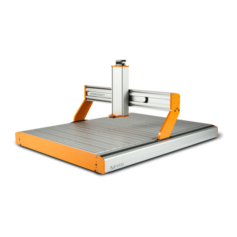
STEPCRAFT MM-1000 Assembly instructions

1
IMPORTANT: Read before using
Operating/Safety
Instructions
(WinPC-NC)
Original Operating/Safety
Instructions
Date of: 11-15-2018
Tool Change Attachment for STEPCRAFT
MM-1000, Kress and AMB 800 FME
Call for consumer information
Customers from outside the U.S.
STEPCRAFT GmbH & Co. KG
An der Beile 2
58708 Menden
Germany
Phone: 0049-2373-179 11 60
E-Mail: info@stepcraft-systems.com
Customers from the U.S. / Canada
STEPCRAFT Inc.
59 Field Street, Rear Building
Torrington, CT, 06790
United States
Telefon: 001-203-5561856
E-Mail: info@stepcraft.us

NOTICE
All instructions, warranties and other collateral documents are subject to change at the sole discretion of
STEPCRAFT, Inc. For up-to date product literature, visit www.stepcraft-systems.com for customers from Europe
or www.stepcraft.us for customers from US / Canada and click on the service & support tab for this product.
Meaning of Special Language
The following terms are used throughout the product literature to indicate various levels of potential harm when
operating this product: The purpose of safety symbols is to attract your attention to possible dangers. The safety
symbols, and their explanations, deserve your careful attention and understanding. The safety warnings
themselves do not eliminate any danger. The instructions or warnings they give are not substitutes for proper
accident prevention measures.
NOTICE
Procedures, which if not properly followed, create a possibility of physical property damage
AND a little or no possibility of injury.
CAUTION
Procedures, which if not properly followed, create a probability of physical property damage
AND a possibility of serious injury.
WARNING
Procedures, which if not properly followed, create a probability of property damage, collateral
damage, serious injury or death OR create a high probability of superficial injury.
Safety Alert: Indicates caution or warning. Attention is required in order to avoid serious
personal injury.
Read the ENTIRE instruction manual in order to become familiar with the features of the
product and how to operate them. Failure to operate the product correctly can result in damage
to the product, personal property and cause serious injury, electric shock and/or fire.
This is a sophisticated hobby and semi-professional product for advanced craftsmen with previous experience in
the operation of tools such as electric drills, routers and computerized tools like CNC routers or 3D printers. It
must be operated with caution and common sense and requires some basic mechanical ability. Failure to operate
this product in a safe and responsible manner could result in personal injury or damage to the product or other
property. This product is not intended for use by children without direct adult supervision. Do not attempt
disassembly, use with incompatible components or augment product in any way without the approval of
STEPCRAFT GmbH & Co. KG or STEPCRAFT, Inc. This manual contains instructions for safety, operation and
maintenance. It is essential to read and follow all the instructions and warnings in the manual, prior to assembly,
setup or use, in order to operate correctly and avoid damage or serious injury.
Age Recommendation: For advanced handcrafters ages 14 and above. This is not a toy.
SAVE ALL WARNINGS AND INSTRUCTIONS FOR FUTURE REFERENCE.
Should you encounter any doubts or require any further information, please do not hesitate to contact us
before commissioning of the power tool. Our contact details can be found on the front page of this
manual.
The term “power tool” in the warnings refers to your mains-operated (corded) power supply and the STEPCRAFT
MM-1000 respectively the Kress milling spindle in connection with the Tool Change Attachment.
General Power Tool Safety Warnings
Work area safety
Keep work area clean and well lit. Cluttered or dark areas invite accidents.
Do not operate power tools in explosive atmospheres, such as in the presence of flammable
liquids, gases or dust. Power tools create sparks which may ignite the dust or fumes.
NOTICE
Keep children and bystanders away while operating a power tool. Distractions can cause you to
lose control and can result in accidents.
Continued on next page

3
Electrical safety
Power tool plugs must match the outlet. Never modify the plug in any way. Do not use any
adapter plugs with earthed (grounded) power tools. Unmodified plugs and matching outlets will
reduce the risk of electric shock.
Avoid body contact with earthed or grounded surfaces such as pipes, radiators, ranges and
refrigerators. There is an increased risk of electric shock if your body is earthed or grounded.
Do not expose power tools to rain or wet conditions. The spindle is only suitable for indoor use.
Water entering a power tool will increase the risk of electric shock.
Do not misuse the cord. Never use the cord for carrying, pulling or unplugging the power
tool. Keep cord away from heat, oil, sharp edges or moving parts. Damaged or entangled
cords increase the risk of electric shock.
If operating a power tool in a damp location is unavoidable, use a Ground Fault Circuit
Interrupter (GFCI).The use a GFCI reduces the risk of electric shock.
Personal safety
Stay alert, watch what you are doing and use common sense when operating a power tool.
Do not use a power tool while you are tired and/or under the influence of drugs, alcohol or
medication. A moment of inattention while operating power tools may result in serious personal
injury.
NOTICE
All persons who operate the power tool must have read and fully understood all relevant
operating instructions. Misunderstanding may result in personal injury.
Use personal protective equipment. Always wear eye protection. Protective equipment such as
dust mask or hearing protection used for appropriate conditions will reduce personal injuries.
Prevent unintentional starting. Ensure the switch is in the off-position before connecting the
power tool to the power source, picking it up or carrying the tool. Carrying power tools with
your finger on the switch or energizing power tools that have the switch on invites accidents.
NOTICE
Remove any adjusting key or wrench before turning the power tool on. A wrench or a key left
attached to a rotating part of the power tool may result in personal injury.
Do not overreach. Keep proper footing and balance at all times. This enables better control of
the power tool in unexpected situations.
NOTICE
Dress properly. Do not wear loose clothing or jewelry. Keep your hair, clothing and gloves
away from moving parts. Loose clothes, jewelry or long hair can be caught in moving parts.
If devices are provided for the connection of dust extraction and collection facilities, ensure
these are connected and properly used. Use of dust collection can reduce dust-related hazards.
Power tool use and care
Do not force the power tool. Use the correct power tool for your application. The correct
power tool will do the job better and safer at its dedicated rate for which it was designed.
NOTICE
Do not use the power tool if the switch cannot be turned on and/or off. Any power tool that
cannot be controlled with the switch is dangerous and must be repaired.
Disconnect the plug from the power source and/or the battery pack from the power tool
before making any adjustments, changing accessories, or storing power tools. Such
preventive safety measures reduce the risk of starting the power tool accidentally.
Store idle power tools out of the reach of children and do not allow persons unfamiliar with
the power tool or these instructions to operate the power tool. Power tools are dangerous in
the hands of untrained users.
NOTICE
Maintain power tools. Check for misalignment or binding of moving parts, breakage of parts
and any other conditions that may affect the power tool's operation. If damaged, have the
power tool repaired before use. Many accidents are caused by poorly maintained power tools.
Keep cutting tools sharp and clean. Properly maintained cutting tools with sharp cutting edges
are less likely to bind and are easier to control by the machine.
Use the power tool, accessories and end mills etc. in accordance with these instructions,
taking into account the working conditions and the work to be performed. Use of the power
tool for operations different from those intended could result in a hazardous situation.
Continued on next page

4
Service
Have your power tool serviced by a qualified repair person using only identical replacement
parts. This will ensure that the safety of the power tool is maintained.
Safety Rules for Rotary Tools
Make sure that the power tool cannot cut its own cord, therefore never install the power cord
across the machine table. Cutting a "live" wire may shock the operator.
Use clamps or another practical and secure way to support the workpiece and secure it to
the machine table. Holding the workpiece with your hands leaves it unstable and may lead to loss
of control.
NOTICE
Accessories must be rated for at least the speed recommended on the tool warning label.
Accessories running over rated speed can fly apart and cause injury.
Always disconnect the power cord from the power source before making any adjustments or
attaching any accessories. You may unexpectedly cause the tool to start leading to serious
personal injury.
Be aware of the switch location, when placing the tool down or when picking the tool up. You
may accidentally activate the switch.
Do not hold the Tool Changer in your hands during the start-up. The reaction torque of the
motor, as it accelerates to full speed, can cause the shaft to twist.
NOTICE
Always wear safety goggles and dust mask. Use only in well ventilated area. Using personal
safety devices and working in safe environment reduces risk of injury.
After changing the bits or making any adjustments, make sure the ER collet and the
clamping nut are both securely tightened. Loose adjustment devices can unexpectedly shift,
causing loss of control. Loose rotating components will be violently thrown.
This is not a handheld tool. The Tool Changer is designed to be system-guided and must be
operated in a CNC router or CNC System. Operation of the power tool handheld may result in
serious personal injury.
NOTICE
Do not reach in the area of the spinning bit. The proximity of the spinning bit to your hand may
not always be obvious.
NOTICE
Do not operate wire and bristle brushes with the spindle. Bristles or wires will be discharged
from the brush at high speeds, can fly apart and cause injury.
Never use dull or damaged bits. Sharp bits must be handled with care. Damaged bits can
snap during use. Dull bits require more force to cut the tool, possibly causing the bit to break.
Use clamps to support workpiece. Never hold a workpiece with your hands.
Inspect your workpiece before cutting. For example, if carving wood, make sure there are no
nails or foreign objects in the workpiece. Nails or foreign objects can cause the bit to break.
The speed and feed with the bit into the material when carving, routing or cutting is very
important. Always observe the speed and feed for the particular bit recommended.
If the workpiece or bit becomes jammed or bogged down, turn the power tool "OFF" by the
switch. Wait for all moving parts to stop and unplug the tool, then work to free the jammed
material. If the switch to the tool is left "ON" the tool could restart unexpectedly causing serious
personal injury.
NOTICE
Do not leave a running tool unattended, turn power off. Only when tool comes to a complete
stop and is disconnected from the mains is it safe.
Do not touch the bit or collet after use. After usage bit and collet are too hot to be touched with
bare hands.
Clean the tool's air vents every 4 hours by using compressed air. Excessive accumulation of
powdered metal inside the motor housing may cause electrical failures.
NOTICE
Do not allow familiarity gained from frequent use of your rotary tool to become
commonplace. Always remember that a careless fraction of a second is sufficient to inflict severe
injury.
Do not alter or misuse tool. Any alteration or modification is a misuse and may result in serious
personal injury.
This product is not intended for use as a dental drill, in human or veterinary medical
applications. Serious personal injury may result.
Continued on next page

5
When using the end mills, V-bits or cutters, always have the workpiece securely clamped.
Never attempt to hold the workpiece with your hands while using any of these accessories.
The reason is that these tools will grab if they become slightly canted in the groove, and can
kickback causing loss of control resulting in serious injury.
Safety Rules for system-guided Tools
The Tool Changer needs to be controlled by a control software of a CNC router. Therefore the
power supply of the spindle has to be properly connected to the external output of the main
board of the CNC router via a 15-pin Sub-D cable. Prior to each commissioning of the power tool
the ON/OFF, speed and emergency button functionality has to be checked. Malfunction may result
in serious personal injury.
NOTICE
Do not leave a running CNC system and power tool unattended, turn power off. Only when a
CNC router or power tool comes to a complete stop and are disconnected from the mains are they
safe.
Additional Safety Warnings
Depending on the application field of the machine (private or commercial), observe the applicable
occupational safety and health, safety and accident prevention and environmental regulations, too.
NOTICE
GFCI and personal protection devices like electrician's rubber gloves and footwear will
further enhance your personal safety.
Do not use AC only rated tools with a DC power supply. While the tool may appear to work, the
electrical components of the AC rated tool are likely to fail and create a hazard to the operator.
Develop a periodic maintenance schedule for your tool. When cleaning a tool be careful not to
disassemble any portion of the tool. Certain cleaning agents such as gasoline, carbon tetrachloride,
ammonia, etc. may damage the surface.
Risk of injury to user. The power cord must only be served by a STEPCRAFT service facility.
Some dust created by power cutting, routing, milling, drilling, and other construction
activities contains chemicals known to cause cancer, birth defects or other reproductive
harm. Some examples of these chemicals are: Lead from nonferrous metals with lead
content, carbonate from carbon fiber, arsenic and chromium from chemically-treated lumber.
Your risk from exposures to these varies, depending on how often you do this type of work. To
reduce your exposure to these chemicals: work in a well ventilated area, and work with approved
safety equipment, such as those dust masks that are specially designed to filter out microscopic
particles.

6
Symbols
IMPORTANT: Some of the following symbols may be used on your tool. Please study them and learn their
meaning. Proper interpretation of these symbols will allow you to operate the tool better and safer.
Symbol
Name
Designation/Explanation
V
Volts
Voltage (potential)
A
Amperes
Current
Hz
Hertz
Frequency (cycles per second)
W
Watt
Power
Kg
Kilograms
Weight
Min
Minutes
Time
S
Seconds
Time
mm
Length, Height, Width
Size in millimeter (metric)
inch
Length, Height, Width
Size in inch
Ø
Diameter
Size of drill bits, end mills, etc.
…/min
Revolutions or reciprocation per
minute
Revolutions, turns, etc. per minute
V→, V↓
Speed
Horizontal / vertical speed in millimeter per second
0
Display off position
Zero speed / revolution per minute
15, 45, 75, 99
Display selector settings
Speed / revolution per minute as percentage share
of the max. speed / revolution. Higher number
means greater speed. 99 equals the max. revolution
per minute.
→
Arrow
Action in the direction of an arrow
Warning symbol
Alerts user to warning messages
CAUTION hot surface
Alerts user not to touch the surface – danger of
burns
CAUTION rotating tool
Alerts user not to touch the blade / the insertion tool -
danger of lacerations
Wear eye protection symbol
Alerts user to wear protective glasses
Wear hand protection symbol
Alerts user to wear protective gloves
Grounding symbol
Alerts user to ground the power tool / electrical
system
Wear ear protection symbol
Alerts user to wear a hearing protector
Read manual symbol
Alerts user to read manual BEFORE first
commissioning
Unplug symbol
Alerts user to unplug the device BEFORE servicing
the power tool
Disposal symbol
Instructions for disposal of WEEE by users of the
European Union

7
CONTENT
1General Instructions .....................................................................................................9
1.1 Information and Explanations to the Operating Instructions......................................9
1.2 Description of Components ......................................................................................9
1.3 Intended Use..........................................................................................................10
2Design and Function...................................................................................................10
2.1 Designation of the Individual Parts of the Tool Change Attachment .......................10
2.2 Designation of the Individual Parts of the Tool Magazine .......................................10
2.3 Designation of the Individual Parts of the Control Module (incl. Pneumatic Valve) .10
2.4 Designation of the Auxiliary Tools ..........................................................................11
3Start-up ........................................................................................................................11
3.1 Mounting the Tool Change Attachment onto the Spindle........................................11
3.2 Inserting the Control Module into the Stepcraft Switch-Box ....................................12
3.3 Pneumatic Connection of the Tool Changer ...........................................................12
3.4 Electric Connection of the Switch-Box....................................................................12
3.5 Installation of the Tool Changer on the STEPCRAFT CNC System.......................12
3.6 Installation of the Tool Magazine............................................................................12
3.7 Handling of ER Collets for SK15.............................................................................13
3.8 Setup of the Tool Magazine in WinPC-NC..............................................................13
3.9 Macro Programming in WinPC-NC.........................................................................15
3.9.1 Macro Hold Tool..............................................................................................15
3.9.2 Macro Store Tool.............................................................................................15
3.10 Test of the Automatic Tool Change Function..........................................................16
3.11 Environmental Conditions ......................................................................................16
3.12 Optional Accessories..............................................................................................17
3.13 Tool Holders SK15 .................................................................................................17
3.13.1 Tool Magazine.................................................................................................17
4Operation Switch-Box / Tool Change Attachment ....................................................17
4.1 Operator.................................................................................................................17
4.2 Tool Change Attachment / Switch-Box ...................................................................19
4.3 Emergency Stop Switch .........................................................................................19
5Technical Specifications.............................................................................................19
5.1 Dimensions and Weight of the Tool Change Attachment........................................19
5.2 Other Characteristics of the Tool Change Attachment............................................19

8
6Transport / Storage .....................................................................................................19
6.1 Transport................................................................................................................20
6.2 Packaging ..............................................................................................................20
6.3 Storage ..................................................................................................................20
7Maintenance ................................................................................................................20
7.1 Service ...................................................................................................................20
7.2 Maintenance Work .................................................................................................20
8Failures ........................................................................................................................21
8.1 Response to Malfunctions ......................................................................................21
9Annex ...........................................................................................................................21
9.1 Warranty and Service Contact Information .............................................................21
9.2 Manufacturer..........................................................................................................21
9.3 Copyright................................................................................................................22
9.4 Limited Warranty ....................................................................................................22
9.5 Instructions for disposal of WEEE by Users of the European Union .......................23
9.6 RoHS, 2002/95/EC.................................................................................................24
9.7 EC Declaration of Conformity .................................................................................25

9
1 GENERAL INSTRUCTIONS
1.1 INFORMATION AND EXPLANATIONS TO THE OPERATING INSTRUCTIONS
This manual is intended to familiarize you with your STEPCRAFT Tool Change System (hereafter
referred to as TCS) and its control system, providing you with all the necessary information you will
need in order to operate the device safely and professionally.
Please read this manual thoroughly and carefully prior to the first use of your
STEPCRAFT TCS. Operate the machine and the associated control system only when
you are sure that you have understood these instructions in their entirety. Hereby you
minimize the risk of injury and / or prevent property damage.
Should you encounter any doubts or require any further information, do not hesitate to contact us. Our
contact information can be found on the front page of this manual.
Keep this manual always in close proximity to the STEPCRAFT TCS for future reference.
Only apply the components according to their intended use (see point 1.3).
We cannot be held accountable either for any kind of injury and / or property damage resulting from
non-intended usage and improper handling deviating from the recommended use of the STEPCRAFT
TCS or from failure to follow the safety regulations properly (see page 2).
In case of a lack of maintenance (see point 7) and / or incorrect operation of the individual parts all
warranty claims are not-applicable.
We reserve the right to further develop the TCS.
1.2 DESCRIPTION OF COMPONENTS
The STEPCRAFT TCS for the STEPCRAFT MM-1000, Kress and AMB 800 FME basically consists of
the Tool Change Attachment, the control module incl. the pneumatic valve (suitable for the
STEPCRAFT Switch-Box) and the tool holders. The Tool Change Attachment has a 43 mm collar as
well as an active sealing air. The milling cutters are clamped using tool holders (similar to SK10) with a
direct collet. The side air outlet feeds the pneumatic change function. The lateral shaft lock button
allows for a convenient tool change. The ring clamping nut allows for a secure clamping connection to
the STEPCRAFT MM-1000 resp. Kress milling spindle / AMB 800 FME.
The delivery scope consists of the following components:
1. Tool Change Attachment, fully assembled
2. Control module incl. pneumatic valve (opt.)
3. 4 m connection hose ø 6 mm
4. 6-fold tool magazine incl. mounting bases and mounting kit
5. Operating / Safety instructions manual
6. Calibration pin and locking screw
7. Control unit incl. pneumatic valve (opt,)
8. Switch-Box (opt.)
For more information on optional accessories, see item 3.12 of this manual.

10
1.3 INTENDED USE
The STEPCRAFT TCS for the STEPCRAFT MM-1000, Kress and AMB 800 FME has been developed
for private users (e. g. model designers) and for single or small batch production in the commercial
sector. It is not suitable either for large-scale production or for integration into assembly lines. It is
designed for the usage of cutters and engraving burins with a diameter up to 6 mm. The system is
specifically designed for mounting onto the STEPCRAFT MM-1000 and the Kress milling spindles types
FM / FME / FME-1 / FME-Q and AMB 800 FME
2 DESIGN AND FUNCTION
2.1 DESIGNATION OF THE INDIVIDUAL PARTS OF THE TOOL CHANGE
ATTACHMENT
1 = Clamping ring with 2x M6 clamping screws
2 = 43 mm Euro-neck intake
3 = SK15 Conical holder
4 = 43 mm spindle clamping tool
5 = Connecting conus
6 = Air connection tool change function
7= SK15 Tool holder
2.2 DESIGNATION OF THE INDIVIDUAL PARTS OF THE TOOL MAGAZINE
1 = Socket head screw M4x8, M4x20 or M4x30
2 = Tool magazine (6-fold)
3 = Spacer
4 = Magazine bases
Depending on the desired height of the magazine use none, one or two spacers.
Please use the appropriate screws.
2.3 DESIGNATION OF THE INDIVIDUAL PARTS OF THE CONTROL MODULE (INCL.
PNEUMATIC VALVE)
1 = Control module (electronic)
2 = Holding screw M3x4
3 = Bulkhead fitting ø 6 mm
4 = Pneumatic valve
5 = Hose fitting ø 6 mm
6 = Pneumatic hose ø 6 mm
4
5
2
1
3
6
7

11
2.4 DESIGNATION OF THE AUXILIARY TOOLS
Calibration pin Locking screw
3 START-UP
3.1 MOUNTING THE TOOL CHANGE ATTACHMENT ONTO THE SPINDLE
For the mounting of the Tool Change Attachment you are in need of a STEPCRAFT MM-1000, Kress
milling spindle 530 FM, 800 FME, 800 FME-Q or 1050 FME-1 or AMB 800 FME the Tool Change
Attachment, the respective operating instructions (OI) and the locking screw.
Preparations of the spindle
Unscrew the collet nut incl. collet from the spindle
shaft.
Preparations of the Tool Change Attachment
Unscrew the air connection of the tool change function
(part 6, point 2.1). Take the locking screw (point 2.4)
and insert it into the now available threaded hole. Turn
the spindle shaft until the locking pin is congruent with
the locking hole of the spindle shaft. Tighten the locking
pin manually. The spindle shaft should not be able to be
twisted anymore. Unscrew the ring clamping nut (part 1,
see point 2.1) so far for it to be flush with the 8 clamping
tongue.
Mounting the Tool Change Attachment onto the spindle
Take the spindle, press and hold the locking pin.
Push the Tool Change Attachment over the 43 mm
collar of the spindle and screw the whole device
slightly hand tight onto the spindle shaft. Afterwards,
release the locking pin.
Unscrew the locking pin and insert the air connection
for the tool change function again into the threaded
hole. The shaft of the Tool Change Attachment incl. the
shaft of the spindle should be able to be twisted easily.
Clamp both components by tightening the clamping screws of the
clamping ring.
From now on, this unit will be referred to as the Tool Changer (TC).
You can disassemble the system in the exact reverse order.

12
3.2 INSERTING THE CONTROL MODULE INTO THE STEPCRAFT SWITCH-BOX
If you have bought both components simultaneously, this task has already been managed by
STEPCRAFT. Proceed with point 4.3.
If you have bought these components separately, the assembly has not taken place yet. You can find all
the information in the documentation for the STEPCRAFT Switch-Box.
3.3 PNEUMATIC CONNECTION OF THE TOOL CHANGER
The TC is being connected to the air outlet of the STEPCRAFT Switch-Box with the hose enclosed
(ø 6 mm). Please hold this hose only as long as needed.
The air inlet of the STEPCRAFT Switch-Box is being connected to the outlet of the compressor. You will
find suitable adapters among the accessories (point 3.12). The compressor should supply between 8
and 10 bar compressed air.
3.4 ELECTRIC CONNECTION OF THE SWITCH-BOX
Connect the Switch-Box with the STEPCRAFT CNC System using the enclosed 15-pin connecting
cable.
Afterwards, connect the STEPCRAFT Switch-Box with the Switchable Socket using the supplied 15-pin
connecting cable. Insert the supply of the spindle into the Switchable Socket.
3.5 INSTALLATION OF THE TOOL CHANGER ON THE STEPCRAFT CNC SYSTEM
Insert the clamping surface (part 2, point 2.1) of the TC completely into the ø 43 mm Euro-neck intake of
your STEPCRAFT CNC System. The locating surface of the TC should rest upon the orange Euro-neck
collar. Now, clamp the TC by tightening the tensioning screw of the Euro-neck collar.
3.6 INSTALLATION OF THE TOOL MAGAZINE
We recommend the mounting of the magazine at the right rear of the machine in X-orientation.
This position will always be circuited during a reference movement. Thus, it will get the least in the way
and the risk of a collision is minimized. It is sufficient for the center of the tool pockets to be barely
positioned in the travel range of the Y-axis. The following illustration shows the position of the holes
(ø 5 mm with M6 thread), with the dimensioning of the rear and the right, that need to be drilled into the
machine table. These dimensions are valid for all sizes of the STEPCRAFT 1 as well as the
STEPCRAFT 2 machine series. If you want to attach a second tool magazine (and extend to 12 tool
pockets), you can find the respective drill positions in parentheses.
Tip: Drill the holes precisely, only an absolutely plane magazine can be easily setup in the software.
The dimensions are measured on the dismounted plate.
Machine table STEPCRAFT 1 series: Machine table STEPCRAFT 2 series:

13
3.7 HANDLING OF ER COLLETS FOR SK15
The collets must snap into the clamping nut. Only then, a correct clamping of the end mill and, above
all, a re-release of the collet are possible. With the help of a spanner you can tighten the collets
optimally.
Change of ER collets
1.
Move tongue of clamping
nut diagonal into the ER
collet until a click is being
heard (pic. 1).
2.
If the ER collet is in the
correct position (pic. 2),
cutters, end-mills, etc.
can be inserted.
3.
Pic. 3 shows the wrong
insertion of the ER collet.
3.8 SETUP OF THE TOOL MAGAZINE IN WINPC-NC
Preparation:Take a tool holder (part 7, point 2.1) and the calibration pin (point
2.4) as an auxiliary tool. Insert this all the way into the tool holder and brace it
with a clamping nut.
Download the file with the machine parameters “Milling with the Tool Changer“ from our website
(Menu_Service & Support_Machine parameters) and save it on your PC.
Get the machine ready for use, start the software and open the suitable parameter file for your machine
type and size via the function Load machine setup in WinPC-NC. Restart the software and execute a
reference movement.
By pressing the manual tool change button (see instruction Switch-
Box), the collet is being opened in the interior of the TC. Press the
button and clamp the prepared tool holder with the calibration pin
into the TC.
Move the calibration pin in the manual mode barely above the tool
pocket 1 (far right in the magazine), as shown in the picture.
Move exactly in the position where you can dip into the tool
magazine from above without touching it with the smaller diameter
of the calibration pin. Move slowly downwards until the greater
diameter is barely above the top edge of the magazine (see
picture 1, right side).
Correct the X- and Y-position in order for the greater diameter to dip
into the exact center of the magazine without bending it in any
direction.
Move the Z-axis downwards until the calibration pin of the magazine
touches the locating surface. This position is the measuring position

14
of the tool pocket place 1. Note down the dimensions of the machine coordinates (upper coordinate field
in WinPC-NC, move manually) in the lower table.
You can round up the dimensions onto a decimal place. Conduct this step for all future tool pocket
places.
Tool no.
X-coordinate
Y-coordinate
Z-coordinate
1
205,1
217,1
20,7
2
180,1
217,1
20,7
3
155,1
217,1
20,7
4
130,1
217,1
20,7
5
105,1
217,1
20,7
Dimension table for the measuring position of the tool pocket places (with exemplary figures)
Tool no.
X-coordinate
Y-coordinate
Z-coordinate
1
2
3
4
5
Transfer the machine coordinates into the next table with the dimensions for the position of the
automatic tool change.
For this purpose proceed as follows:
1. Transfer the values of the X-coordinates 1:1 into the column of the X-position.
2. The values of the Y-position are calculated based on this formula:
Y-coordinate - 25 = Y-position
3. Transfer the values of the Z-coordinates 1:1 into the column of the Z-position.
Tool no.
X-position
Y-position
Z-position
1
205,1
192,1
20,7
2
180,1
192,1
20,7
3
155,1
192,1
20,7
4
130,1
192,1
20,7
5
105,1
192,1
20,7
Dimension table for the position for the of the automatic tool change (with exemplary figures)
Tool no.
X-position
Y-position
Z-position
1
2
3
4
5

15
Enter the determined values into the software:
3.9 MACRO PROGRAMMING IN WINPC-NC
In WinPC-NC many complex functions can be controlled with the help of macros. For the TC they are
preprogrammed for a magazine that is arranged along the X-axis. These can be modified for other
magazine positions by changing the X- and Y-commands.
The following macros are already deposited.
3.9.1 MACRO HOLD TOOL
Speed 25.000 (Machine travels the following commands with 25 mm / second)
MoveY 25.000 (Spindle moves 25 mm backwards, above the tool holder)
MoletteOpen (Collet opens)
MoveZ 35.000 (Spindle moves 35 mm downwards above the tool change holder)
MoletteClose (Collet closes, tool holder is being tensioned)
Speed 10.000 (Machine travels the following commands with 10 mm / second)
MoveY -25.000 (Spindle moves 25 mm forwards and pulls the tool holder out of the magazine)
Speed 25.000 (Machine travels the following commands with 25 mm / second)
MoveZ -35.000 (Spindle moves 35 mm upwards into the original position)
3.9.2 MACRO STORE TOOL
Speed 25.000 (Machine travels the following commands with 25 mm / second)
MoveZ 35.000 (Spindle moves 35 mm downwards, in front of the tool magazine)
Speed 10.000 (Machine travels the following commands with 10 mm / second)
MoveY 25.000 (Spindle moves 25 mm backwards and inserts the tool holder into the
magazine)
MoletteOpen (Collet opens, tool holder is being released)

16
Speed 25.000 (Machine travels the following commands with 25 mm /second)
MoveZ -35.000 (Spindle moves 35 mm upwards above the tool holder)
MoletteClose (Collet closes)
MoveY -25.000 (Spindle moves 25 mm forwards into the original position)
3.10 TEST OF THE AUTOMATIC TOOL CHANGE FUNCTION
The machine should be ready-to-use and the TC should be supplied with compressed air. The spindle
should be located in approx. the middle of the X- and Y-axis in order for the magazine to be traveled to
from the front.
Insert one tool holder each into the tool pockets 1 and 2; there should be no tool clamped in the TC.
Open the menu Move_Select tool in WinPC-NC.
The active tool (red arrow) is shown at the bottom left of the screen. Because no tool is clamped in the
spindle right now, it shows 0. Take care that the shown tool is also clamped into the TC before starting
each job.
Press 1 in the hold tool column (see blue arrow). The TC should now automatically take up tool 1 (left
rear).
Press 2 in the store tool column. The TC should now automatically store tool 1 and take up tool 2.
3.11 ENVIRONMENTAL CONDITIONS
Only setup and operate the TC in indoor environments. The air surrounding the TC is to be kept low-
dust. An excessive exposure to dust may cause damage to the TC.
Humidity should be within the usual levels for indoor environments. Protect the TC against moisture and
humidity. The ideal temperature of the system is between 18°C and 25°C.
Especially protect the electronics from overheating by avoiding exposure of the TC as well as the
Switch-Box to direct sunlight or close proximity to a heater.

17
3.12 OPTIONAL ACCESSORIES
Should you use accessories not manufactured or resold by STEPCRAFT, you need to make sure that it
is compatible with your machine. Please contact the respective manufacturer in case you encounter any
doubts.
3.13 TOOL HOLDERS SK15
Please take into consideration that the TC, the spindle as well as the machine can be easily
overcharged when using tool holders with great milling cutters. Use adjusted feed and infeed rates.
Please take in mind that greater tools, which are not being precision-balanced, can lead to strong
vibrations.
The following tool holders are available:
- SK15 tool holder for ER11 collets
3.13.1 TOOL MAGAZINE
The enclosed magazine can always be extended by 6 magazine pockets. The dimensions of the
mounting holes can be gleaned from the illustration (see point 3.6).
Magazine 6-fold incl. 2x magazine bases, 2x M4x8, 2x M4x20, 2x M4x35 fastening screws, 4x spacer
ø 12x12.
4 OPERATION SWITCH-BOX /TOOL CHANGE ATTACHMENT
4.1 OPERATOR
The improper operation of the Tool Changing System can cause serious injury and / or property
damage.
Read and observe the major accident prevention regulations!
Each user must have read and understood the all available instructions for the entire system (machine,
system-held tool, control and software) before proceeding to operate the device for the first time.

18
4.2 INSTALLATION OF THE TOOL CHANGER MODULE IN PLAIN SWITCHBOX
1.
Loosen the four torx screws to open the
housing. Now you can pull the flat ribbon
cable out of the slot.
2.
Remove the two pre-punched metal shafts
with a (pin) puncher or screw driver.
Afterwards you screw the air connections
into the respective openings.
3.
Remove the connected jumper and place the
circuit board onto the provided slot. Fixen
the board with the delivered torx screw
M3x6TX 10.
4.
Connect the two wires (red / black) to the
provided slot and fix the valve with the glue
stripe. Shorten the 6 mm hoses and attach
them as in the following picture 5.
5.
You can now connect the flat ribbon cable to
its original position. Afterwards you can
screw the switchbox housing back together
and the conversion is complete.

19
4.3 TOOL CHANGE ATTACHMENT /SWITCH-BOX
Never touch the tool! There exists a serious risk of injury!
In order to change a tool holder manually, press the tool change button on the Switch-Box and extract
the tool holder.
The tools are clamped without any additional collets into the tool holders. Use a narrow 14 mm spanner
and a 17 mm spanner for this purpose.
4.4 EMERGENCY STOP SWITCH
The emergency stop switch is located on the front of the STEPCRAFT CNC System. Pressing the
emergency button leads to an emergency stop of the machine. The machine will stop immediately (see
point 10 of the respective instruction).
Actuate the emergency stop switch only in emergency situations!
NOTICE: Actuating the emergency stop will result in immediate machine shutdown and can cause step
and data losses.
Controlled cessation of the machine´s operation can only be effectuated via the control software.
To cancel the emergency stop status, turn the emergency stop switch to the right. Then the control is re-
enabled. The work process must be restarted.
The entire system is controlled and operated by the PC.
Prior to first usage, read the manual of your control software thoroughly and carefully,
making sure that you have understood everything.
For questions regarding the control software, please contact the respective software developer.
5 TECHNICAL SPECIFICATIONS
5.1 DIMENSIONS AND WEIGHT OF THE TOOL CHANGE ATTACHMENT
Length / Diameter = 100 mm / 56 mm
Weight = 0,585 kg
Clamping neck = 43 mm (Euro neck)
5.2 OTHER CHARACTERISTICS OF THE TOOL CHANGE ATTACHMENT
Holding system = SK15 (STEPCRAFT Design)
Collets = ER11 (1-8 mm)
Operating pressure = 8-10 bar, integrated sealing air ventilation
Max. rotational speed = 28.000 rpm
True-running accuracy = 0,02 mm out of the center
Housing = Aluminum 7075, anodized
6 TRANSPORT /STORAGE

20
6.1 TRANSPORT
Please make sure that the TC is not exposed to heavy shocks during transport. This can lead to
unwanted vibrations. If necessary, transport the device in suitable containers.
6.2 PACKAGING
If you do not want to re-use the packaging material of the TC, remove it properly and according to
disposal conditions at the site and carry it to the recycling or disposal unit.
6.3 STORAGE
In case of prolonged downtime of the TC and the Switch-Box please observe the following storage
conditions:
- Store the device and its components in an indoor environment.
- Protect from moisture, humidity, cold, heat and direct sunlight.
- Store in a dust-free environment, cover if necessary.
- The storage site should be free of any vibrations.
7 MAINTENANCE
7.1 SERVICE
To ensure continued enjoyment of your STEPCRAFT Tool Changing System, handle it carefully.
Regular maintenance positively affects the life expectancy of the device.
Preventive maintenance performed by unauthorized personnel may cause serious
hazard. We recommend that all tool service be performed by a STEPCRAFT service
facility.
To avoid injury from unexpected starting or electrical shock, always remove plug
from wall outlet before performing service or cleaning.
7.2 MAINTENANCE WORK
To avoid accidents always disconnect the tool from the power supply before
cleaning or performing any maintenance. The tool may be cleaned most effectively
with compressed dry air. Always wear safety googles when cleaning tools with
compressed air.
Please conduct the following maintenance operations on a regular basis:
- Clean the collet cone with a soft cloth.
- Take care that no chips as well as the least amount of dust finds its way into the ventilation
system.
Other manuals for MM-1000
1
Table of contents
Other STEPCRAFT Tools manuals
