Steren INV-400 User manual

Product / Producto: DC TO AC
POWER INVERTER / INVERSOR DE
VOLTAJE 12VCD A 110VCA
Model / Modelo: INV-400, INV-600,
INV-1000
Brand / Marca: Steren
CONDICIONES
1. Para hacer efectiva esta garantía se requiere: La presentación de esta póliza y del producto, en el lugar en donde fue adquirido o en ELECTRONICA STEREN S.A. DE C.V.
2. ELECTRONICA STEREN S.A. DE C.V. se compromete a reparar el producto en caso de estar defectuoso sin ningún cargo al consumidor. Los gastos de transportación
serán cubiertos por el proveedor.
3. El tiempo de reparación en ningún caso será mayor a 30 días contados a partir de la recepción del producto en cualquiera de los sitios en donde pueda hacerse efectiva la
garantía.
4. El lugar donde puede adquirir partes, componentes, consumibles y accesorios, así como hacer válida esta garantía es: En cualquiera de las direcciones arriba mencionadas.
ESTA GARANTIA NO ES VALIDA EN LOS SIGUIENTES CASOS:
1. Cuando el producto ha sido utilizado en condiciones distintas a las normales.
2. Cuando el producto no ha sido operado de acuerdo con el instructivo de uso.
3. Cuando el producto ha sido alterado o reparado por personas no autorizadas por ELECTRONICA STEREN S.A. DE C.V.
Nota: El consumidor podrá solicitar que se haga efectiva la garantía ante la propia casa comercial, donde adquirió el producto. Si la presente garantía se extraviara, el
consumidor puede recurrir a su proovedor para que le expida otra póliza de garantía, previa presentación de la nota de compra o factura respectiva.
DATOS DEL DISTRIBUIDOR
DISTRIBUTION / NOMBRE / DISTRIBUIDOR:
ADDRESS / DOMICILIO:
PRODUCT / PRODUCTO: BRAND / MARCA:
MODEL / MODELO: SERIAL NUMBER / No. DE SERIE:
DATE OF DELIVERY / FECHA DE ENTREGA:
Call Center / Centro de Atención a Clientes
del Interior 01 800 500 9000
Mexico City / Cd. de México: 53 54 22 90
Warranty
CONDITIONS:
1. This warranty card with all the required information, the invoice or purchase ticket, the product box or package, and the product, must be presented with the product
when warranty service is required.
2. If the product stills on the warranty time, the company will repair it free of charge even the transportation charges.
3. The repairing time will not exceed 30 natural days, from the day the claim was received.
4. Steren sells parts, components, consumables and accessories to customer, as well as warranty service, at any of the following addresses:
THIS WARRANTY IS VOID ON THE NEXT CASES:
If the product has been damage by an accident, acts of God, mishandling, leaky batteries, failure to follow enclosed instructions, improper repair by unauthorized
personal, improper safe keeping or otherwise.
Notes:
a) The customer can also claim the warranty service on the purchase establishment.
b) If you lose the warranty card, we can reissue it just showing the invoice or purchase ticket.
V1006
Póliza de Garantía
This Steren product is warranted under
normal usage against defects in
workmanship and materials to the original
purchaser for one year from the date of
purchase.
Garantiza este producto por el término de
un año en todas sus partes y mano de obra
contra cualquier defecto de fabricación y
funcionamiento, a partir de la fecha de
entrega.
INV-400
INV-600
INV-1000

INSTRUCTION MANUAL FOR DC TO AC POWER INVERTER
Model: INV-400, INV-600, INV-1000
Brand: Steren
Before using your new DC to AC power inverter, please read this
instruction manual to prevent any damage. Put it away in a safe place
for future references.
This voltage inverter is an advanced energy conversion tool that can take
direct current (DC) and turn it into an alternate current (AC).
This makes the inverter a versatile tool that can be used in cars, boats,
etc.
In order to use your new voltage inverter safely and efficiently, install and
use it according to the guidelines laid out in this instruction manual.
Read the entire instruction manual paying special attention to the
warnings.
IMPORTANT
Only use the included cables in the package
Take care not to damage the insulation of the cables
Do not overload the inverter
Do not use 6 or 24V batteries
Do not use small diameter cables
Do not operate the equipment near fumes
Do not drop the inverter
Do not allow the inverter get wet
WARNINGS
Keep your voltage inverter away from water and humidity.
Do not use this voltage inverter with electrical systems that have a ground
anode.
This voltage inverter is designed to be used with electrical systems with a
ground cathode.
Make sure to get help from another person in order to operate this voltage
inverter. Do not use alone. Keep this voltage inverter away from children.
SECURITY WARNINGS
The voltage inverter INV-400 will give you an output voltage of 400W AC,
furthermore, INV-600 and INV-1000 will give you 600 and 1000W of power
otuput. Connect into the voltage inverter’s outputs the same kind of
equipment you would to a home energy output.
The voltage inverter will heat up when in use, avoid touching the inverter
or placing the inverter near objects that can not be near extreme heat
including sleeping bags or anything flammable.
Make sure that the DC voltage input is the same voltage as that required
by the voltage inverter and that the charge is the same as required by the
voltage inverter’s output.
Make sure the polarity is not inverted when connecting your inverter.
CONTROLES
1.- ON / OFF power switch ………… This switch turns on / off the
inverter
2.- Power indicator …………………. When lit, it indicates the
inverter has been turned on, and
is ready for use
3.- Surge indicator ………………… Lit on when then inverter has
been turned on / turn it off
when the inverter protection
operates
4.- Dual AC outlets .......................... Allows you to connect
up to 2 different devices
5.- Battery connections posts ……… Allows you to connect the inverter
to the battery, using the included
alligators clips
INSTRUCTIVO DE USO DE INVERSOR DE VOLTAJE 12VCD A 110VCA
Modelo: INV-400, INV-600, INV-1000
Marca: Steren
Antes de utilizar su nuevo Inversor de Voltaje, lea este instructivo
para evitar cualquier mal funcionamiento. Guárdelo para futuras
referencias.
Nuestro Inversor de Voltaje modelo es una avanzada herramienta de
conversión de energía, que puede suministrar los requerimientos de
corriente alterna (~) convirtiéndola de una fuente de corriente directa
(batería de automóvil). Esto lo hace una herramienta versátil que puede
ser utilizada en autos, barcos y casas de campaña. También puede ser
usado cuando existe falla de suministro de energía.
Para poder utilizar su Inversor de Voltaje con eficiencia y seguridad,
instale y use el mismo apropiadamente. Lea completamente este
instructivo y siga todas las instrucciones de instalación, especialmente las
advertencias y los avisos.
Los avisos indican la probabilidad de destruir el inversor u otra aplicación
y las Advertencias indican la probabilidad de daños a las personas.
IMPORTANTE
Utilice los cables suministrados en el empaque
Tenga cuidado de no dañar el aislante de los cables
No sobrecargue el inversor.
No utilice baterías de 6 o de 24V
No utilice cables de diámetro pequeño
No utilice el equipo cerca de lugares con humo
No deje caer el inversor
No permita que el inversor se moje
AVISOS
Mantenga el Inversor lejos de la humedad y los líquidos
No utilice con sistemas eléctricos de ánodo a tierra
El equipo está diseñado para utilizarse con sistemas eléctricos de cátodo
a tierra
Asegúrese que otra persona le auxilie, no lo opere usted solo
Mantenga alejados a los niños y no permita que jueguen con el Inversor
ADVERTENCIAS DE SEGURIDAD
El Inversor modelo INV-400 le proporciona un voltaje de salida útil de
corriente alterna y una Potencia de 400W, así mismo el INV-600 e
INV-1000 proporcionan una potencia de 600 y 1000W respectivamente,
conecte en los contactos de salida, como en los de su casa, y no ponga
nada en ellos que no sea una clavija de un equipo eléctrico.
La caja del Inversor se calentara cuando este en uso, evite tocar o acercar
cosas y/o materiales que no soportan la alta temperatura, tales como
bolsas de dormir o carpetas, etc.
Asegúrese que la entrada de voltaje de CD es el mismo que el voltaje
requerido por el Inversor y la aplicación eléctrica es el mismo que el
proporcionado por la salida del Inversor.
La sección transversal de los alambres o cables de conexión debe ser la
suficiente para el manejo de corriente. Asegúrese que la polaridad es la
correcta.
CONTROLES
1.- Encendido / Apagado............... Enciende o apaga el inversor
2.- Indicador de uso ..................... Cuando enciende, indica que el
inversor está en uso
3.- Indicador de protección .......... Enciende junto con el indicador
de uso cuando hay salida de
corriente en los contactos / se
apaga cuando entra en operación
la protección del inversor y no
existe salida de voltaje en los
contactos
4.- Contactos ............................... Permite conectar dos equipos
diferentes
5.- Conectores para batería ................... Permite conectar el inversor a la
batería, utilizando los caimanes
incluidos.

6.- High speed cooling fan ……......…… This fan cool the internal circuits,
while the inverter is in use
7.- Ground connector(Only INV-1000) .. Allows you to ground the
inverter
8.- Restore button …………………….... Press this button after the inverter
protection operates, in this way,
the equipment will works correctly
after this process
6.- Ventilador ......................................... Permite enfriar los circuitos
internos del inversor mientras
esté en uso
7.- Conector a tierra (Solo INV-1000) .... Conecte el cable incluido a tierra
(al chasis)
8.- Reinicio (sólo INV-400 e INV-600) ... Presione este botón después de
que el sistema de protección se
active. El equipo volverá a
funcionar de manera normal
1
23
45
67
INV-1000
1
23
4
6
5
8
INV-400
1
23
4
8
6
5
INV-600

Notes:
Even in OFF position, the inverter consumes a low level of power from the
battery.
Make sure do not overload the maximum inverter voltage capacity (400,
600, 1000W, depending of the model).
Pay attention to polarity when plug the alligators to the battery. Red
terminal is positive (+) and black terminal is negative (-).
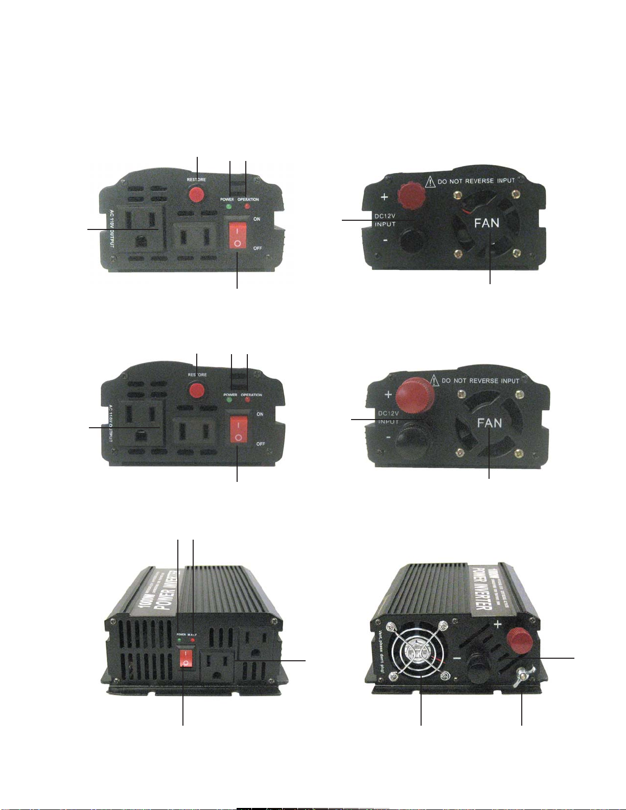
INSTALLATION
a) Selecting the battery power source
You must use a power source with a minimum voltage of 10,5V and a
maximum voltage of 14,5V DC, in order to connect it to the inverter.
The power source can be a combination of car’s battery and alternator
(when the car’s motor is running).
Caution:
Do not install the power inverter in a positive ground DC system.
The power inverter must be connected to batteries or power sources with
a normal / average voltage of 12V. The power inverter won’t operates with
6V or 24V power sources.
b) Placing the power inverter
The place where you want to install the inverter is very important, in order
to maximize their use and extend the life of the inverter. For better results,
the inverter must be placed in a sturdy, flat surface. You can place the
equipment in a vertical or horizontal position.
Keep in mind these points when you select a permanent place for the
inverter:
1.- Ventilation: make sure to have at least 1 inch of clearance around the
inverter, for a better air flow. Do not place objects over the inverter while is
in use. The air should circulate freely. The built-in fan provides air, but
must have enough free space around it to operate correctly.
2.- Keep the equipment dry and far from liquids. Place it far away spill
areas.
3.- Best operating temperature is from 7° to 30°C. Do not place the
inverter in a place near to heat tubes or any other heat sources, that can
overheat the inverter.
4.- Do not place the inverter near to flammable substances. Fumes and
gas may cause an explosion or fire that can result in several damages and
possible death.
c) Connection cables from inverter to battery
The power inverter includes 2 4AWG cables (45cm length) with
eye-type and alligator ends to connect it the inverter to a battery. You can
identify the negative end with a black color and the positive end with a red
color.
Please, place the inverter as close as possible to the battery, in order to
get the best performance.
d) Grounding the inverter (Only INV-1000)
Do not install the inverter in a positive ground DC system.
To identify a positive ground DC system, look for the positive terminal of
the battery connected to the chassis or to a central grounding point.
e) Connecting to a power source
Usually, the power source is a battery (or group of batteries) which is
recharged by an alternator.
1.- Make sure the inverter’s power switch is on OFF position and there are
no liquids near of it.
2.- Connect the eye-type terminals (supplied with the inverter). Place the
black cable in the middle of the negative connector (-), and place the red
cable in the positive connector (+).
3.- Tighten the screws firmly to hold the cables.
Notas:
Aún cuando el equipo esté apagado, el inversor consumirá una cantidad
pequeña de corriente de
la batería.
Asegúrese de que el voltaje combinado no exceda la capacidad del
inversor (400, 600 o 1000W, dependiendo el modelo).
Asegúrese de poner atención a la polaridad al momento de colocar los
caimanes. Rojo es positivo, Negro es negativo.
INSTALACIÓN
a) Seleccionando la batería de fuente de energía
La fuente de energía que debe utilizar para conectar el inversor debe
tener un voltaje mínimo de 10,5V a un máximo de 14,5V CD
La fuente de poder puede ser una combinación de la batería del automóvil
y el alternador (cuando el motor del vehículo está en funcionamiento).
Precaución:
No instale el inversor en un sistema con tierra positiva.
El inversor debe ser conectado únicamente a baterías o fuentes de poder
que tengan un voltaje normal o promedio de 12V. El inversor de voltaje no
funcionará en fuentes de 6V o 24V
b) Colocación del inversor de voltaje
La colocación del inversor es importante para maximizar su uso y
prolongar la vida de éste. Para mejores resultados, el inversor debe
colocarse en una superficie plana y firme. Puede colocar el equipo en
posición vertical u horizontal.
Considere los siguientes puntos cuando seleccione un lugar
permanente:
1.- Ventilación: asegúrese de que hay por lo menos tres centímetros de
espacio libre alrededor del inversor para que exista un flujo de aire
correcto. No coloca objetos sobre el inversor durante su uso. El aire debe
circular libremente. El ventilador incluido provee de aire, pero debe tener
suficiente espacio libre para poder operar correctamente.
2.- Mantenga el equipo seco y alejado de líquidos. Colóquelo lejos de
áreas donde pueda gotear algún líquido.
3.- La mejor temperatura de operación es entre 7° y 30°C No coloque el
inversor en un lugar que pueda ser afectado por conductos de calor u
otras fuentes de calor que puedan incrementar la temperatura de
operación normal del inversor.
4.- No coloque el inversor cerca de sustancias flamables. Humo y gases
pueden causar una explosión o fuego que pueden resultar en daños
graves y posiblemente la muerte.
c) Cables de conexión del inversor a la batería
El inversor de voltaje cuenta con 2 cables de 45cm de longitud calibre
4AWG con terminal de ojillo y caimán para conexión a batería. La terminal
negativa está identificada con color negro y la terminal positiva con
cubierta roja.
Recuerde colocar el inversor lo mas cerca posible de la batería para un
mejor desempeño.
d) Aterrizando el inversor (Sólo INV-1000)
Asegúrese de no instalar el inversor de voltaje en un sistema de corriente
directa de tierra positiva.
Para identificar un sistema con tierra positiva, revise la terminal positiva de
la batería conectada al chasis del vehículo o a un punto de aterrizaje
central.
e) Conectando a la fuente de poder
Normalmente, la fuente de poder es una batería (o grupos de baterías) la
cual es recargada por un alternador.
1.- Asegúrese de que el interruptor de encendido del inversor esté en
posición OFF (apagado) y que no hay líquidos cerca de su posición.
2.- Conecte las terminales con ojillo del cable suministrado en el inversor.
El cable negro se conecta dentro del conector negativo (-), y el cable rojo
se inserta en el conector positivo (+).
3.-Asegure los cables, atornillando firmemente los conectores.

4.- Use the red alligator to connect it to negative end (-) in the power
source. At this moment, make sure you placed the negative end in a right
way, from the inverter to the battery.
5.- Use the black alligator to connect the inverter to power source’s
positive end (+).
6.- Turn the inverter on. The indicator light and the surge indicator will
light up.
7.- Turn the inverter. The installation finished.
Notes:
If the polarity is inverted, may cause several and permanent damages in
the inverter.
You will watch some sparks when connect the battery to the inverter.
Make sure there are not flammable liquids near the inverter, may cause an
explosion.
HOW TO USE THE INVERTER
1.- Plug the power cord from the electric device that you want to use with
the inverter, into one of the outlets. Make sure the device is power off
before to connect it in the inverter.
2.- Turn the inverter on.
3.- Turn the electric device on. If you plugged two devices into the inverter,
make sure to turn them on separately, this will insure that the power
inverter does not have power peaks at the moment to turn the device on,
at the same time.
Note:
If you plugged two devices to the inverter, make sure the sum of the
voltages do not exceeds the maximum capacity of the inverter (400, 600,
1000W depending of the model).
BATTERY OPERATION TIME
The battery operation time is dependant on the battery capacity (Ah) and
the charge potency (W). The method to calculate the operation time is:
Battery capacity (Ah) x input voltage / charge potency (W)
Example:
Battery capacity = 80Ah
Input voltage = 12 V
Charge potency = 200 W
(80Ah x 12 V ) / 200 W = 4.8 h
OUTPUT WAVES
The form of the AC output waves is similar to senoidal waves. This kind of
wave is convenient for the majority for most electrical applications.
The modified senoidal wave produced by this inverter has an RMS voltage
which is the same as is produced by home power sources.
Most voltmeters (digital and analog) are sensitive to average AC value.
These are calibrated to detect RMS voltage under the supposition that the
wave shape is a pure formation.
These voltmeters will read the output as 20 – 30 volts. For exact output
voltage measurements, use a voltmeter that will read real RMS.
PROTECTION CHARACTERISTICS
Low voltage protection
The inverter will automatically turn off when the DC voltage is below the
required amount. The input voltage range is 11 – 14 volts. When the DC
voltage is below 11 volts, the buzzer will sound. When the DC voltage is
below 10 volts, the inverter will automatically turn off.
4.- Conecte el caimán rojo en la terminal negativa (-) de la fuente de
poder. En este punto asegúrese de que ha conectado firme y
correctamente la terminal negativa del inversor a la terminal negativa de la
fuente de poder.
5.- Conecte el caimán negro en la terminal positiva (+) de la fuente de
poder.
6.- Encienda el inversor. La luz indicadora de uso y el indicador de
protección se encenderán.
7.- Apague el inversor. La instalación ha concluido.
Notas:
Si la polaridad está invertida puede causar un daño permanente en el
inversor.
Observará que saldrán pequeñas chispas cuando hace la conexión entre
el inversor y la batería. Asegúrese de que no hay líquidos inflamables
cerca, podría ocurrir una explosión.
OPERACIÓN
1.- Conecte el cordón de energía del equipo que desee utilizar en uno de
los contactos del inversor. Asegúrese que este dispositivo esté apagado
antes de conectarlo al inversor.
2.- Encienda el inversor.
3.- Encienda su dispositivo eléctrico. Si conectó dos equipos, asegúrese
de encenderlos por separado, esto le asegurará de que el inversor de
voltaje no tendrá picos de energía al momento de encender las dos
unidades al mismo tiempo.
Nota:
Si conecta dos dispositivos al inversor, asegúrese de que la suma de los
voltajes no exceda la capacidad del inversor (400, 600, 1000W
dependiendo el modelo).
TIEMPO DE OPERACIÓN DE LA BATERÍA
El tiempo de operación de la batería depende de la capacidad de la
batería (Ah) y la potencia de la carga (W), el método para calcular el
tiempo de operación es:
Capacidad de batería (Ah) x el voltaje de entrada / la potencia de la carga
(W).
Ejemplo.
Capacidad de batería = 80 Ah
Entrada de voltaje = 12 V
Potencia de la carga = 200 W
(80 Ah x 12 V ) / 200 W = 4,8 h
FORMA DE ONDA DE SALIDA
La forma de onda de salida de CA es Senoidal Modificada, esta es
similar a la forma de onda útil normal.
Esta clase de forma de onda es conveniente para la mayoría de las
aplicaciones eléctricas, incluyendo fuentes de poder conmutadas y
lineales utilizadas en equipo electrónico, transformadores, motores, etc.
La onda modificada senoidal producida por el inversor tiene un voltaje
RMS (raíz cuadrática media), la cual es la misma de la red de uso
domestico.
La mayoría de los voltímetros (digital y analógico) son sensibles al valor
promedio de CA o a la forma de onda mejor que el valor RMS. Estos
están calibrados para voltaje RMS bajo el supuesto que la forma de onda
medida es una onda senoidal pura. Estos medidores leerán entre 20 y 30
volts en la salida del inversor. Para mediciones de exactitud de la salida
de voltaje de esta unidad, utilice un voltímetro de lectura real RMS.
CARACTERÍSTICAS DE PROTECCIÓN DEL INVERSOR
Protección de bajo voltaje
El inversor automáticamente se apagara cuando el voltaje de CD sea mas
bajo del requerido. El rango de voltaje de entrada al inversor es de 11 a
14V, cuando el inversor recibe menos de 11V, el zumbador sonará
intermitentemente, cuando el voltaje es menor de 10V el inversor
automáticamente se apagará.

High voltage protection
The inverter will automatically turn off when the DC voltage is above the
required amount. The input voltage range is 11 – 14 volts. When the DC
voltage is above 14 volts, the inverter will automatically turn off.
Overcharge protection
The inverter will automatically turn off when the input charge is higher than
the required amount.
Short-circuit protection
The inverter will automatically turn off when a short-circuit occurs.
Temperature protection
The temperature will become too high for the inverter when it is in use for
an extended period of time or when it is not well ventilated. The inverter
will automatically turn off when the temperature reaches 65°C. If you need
to use the inverter for an extended period of time, the charge needs to be
80% of the average. Also, make sure the inverter is well ventilated.
Restore button
You must press this button, after the protection systems is activated. When
you press it, the system will back to initial mode, then you can continue
using the inverter in a normal way.
TROUBLESHOOTING
SPECIFICATIONS
Input: 10-14V
Output: 100-120V ~ 60Hz
Continuous Power output: 1 000W maximum
Frequency: 60Hz
Note:
Product design and specifications are subject to change, without notice.
Protección contra Sobrevoltaje
El inversor automáticamente se apagará cuando la entrada de voltaje de
CD sea más alto del requerido. El rango de voltaje de entrada al inversor
es de 11 a 14V, cuando el inversor recibe más de 14V automáticamente
se apagará.
Protección contra sobrecarga
El inversor se apaga automáticamente cuando la carga es más alta que el
valor promedio de la unidad.
Protección por cortocircuito
El inversor se apagará inmediatamente y se conservará en estado de
sobrecarga cuando ocurre un cortocircuito.
Protección Térmica
La temperatura será muy alta para el inversor cuando este esté en uso
por mucho tiempo o no esté bien ventilado, el inversor se apagará
automáticamente cuando la temperatura alcance 65°C. En caso de que se
requiera que trabaje por largo tiempo, la carga debe ser menos del 80%
del promedio, al mismo tiempo corrija la condición de ventilación.
Botón de reinicio
Deberá presionar este botón después de que el sistema de protección se
ha activado, de esta forma el sistema regresará al modo inicial de uso, y
podrá seguir utilizando el inversor de manera normal.
PROBLEMAS Y SOLUCIONES
ESPECIFICACIONES
Entrada: 10-14V
Salida: 100-120V ~ 60Hz
Potencia: 1 000W máximo
Frecuencia: 60Hz
Nota:
El diseño del producto y las especificaciones pueden cambiar sin previo
aviso.
Problema / Trouble Solución / Solution
Rudio en el sistema de audio cuando el inversor está Algunos equipos de audio de mediana calidad pueden presentar
en uso este problema, compre un filtro de línea AC de alta calidad
Buzz in audio systems while the inverter is in use
Hay interferencia en el televisor cuando el inversor está Cambie de posición el televisor
en uso Ajuste la antena del televisor
TV interference while the inverter is in use
No hay voltaje de salida / No Output Voltage
Cordón no conectado Revise la conexión y asegúrela
Cable not connected Check all connections
Se encuentra en estado de protección Vaya a la sección de configuración
Protection mode See the configuration section
El voltaje de salida no es correcto / The output voltage is not correct
Utilice un Voltímetro digital o analógico Use un voltímetro de lectura verdadera (RMS)
Using a digital or analog voltmeter Use a RMS reading voltmeter
El voltaje de la fuente de CD es muy alto o muy bajo Ajuste el voltaje al nivel requerido
The input DC voltage is too low or too high Adjust the voltage to the requires level
No puede manejar la carga / Unable to manage the charge
La carga es muy grande o la potencia es mayor que el promedio Utilice una carga más baja
The charge is too large or potency is too large Use a lower charge
El alambrado no esta de acuerdo con los requerimientos o la conexión no es segura. Use cable o alambre del calibre adecuado
The cabling is wrong or the connection is not safe Use adequate cables
La potencia de arranque de la aplicación es hasta 2 veces el promedio Trate con otra aplicación
The startup is more than 2 times the average Try another application
This manual suits for next models
2
Table of contents
Other Steren Inverter manuals
Popular Inverter manuals by other brands

Siemens
Siemens SINAMICS V20 Inverter Compact operating instructions

Samlexpower
Samlexpower PST-600-12 owner's manual

Northern Lights
Northern Lights L944D, M944W, NL944D2, M30CW, M944T, NL944T2, and... Operator's manual

True blue power
True blue power TI1200 Installation manual and operating instructions

chinavasion
chinavasion CVSB-LT221 user manual

Kaco
Kaco blueplanet 3.0 NX1 M2 Quick Installation Instruction