Stereotaxis Niobe PM3.1 User manual

EXHIBIT G
Stereotaxis Installation Checklists

985-006001 REV. G Effective Date: 03 June 2008
WARNING: This is a revision controlled document. Verify revision is correct prior to use.
Niobe®
MNS Installation Verification and Testing
for PM3.1 Conversion to PM3.2
and for PM3.2 Conversion to PM3.1
4320 Forest Park Avenue, Suite 100
St. Louis, MO 63108
USA
1-866-646-2346
1-314-678-6100 Manual P.N.: 985-006001
www.stereotaxis.com Revision: G
Effective Date: 03 June 2008

985-006001 REV. G Effective Date: 03 June 2008
Stereotaxis, Inc. Page ii
REVISION HISTORY
Rev
Description
Author
Date
ECO#
-
Initial release for conversion of 1st system
S. Burgett
10-20-04
04-948
A
Remove all references to the joystick (gaming
option) and the printer; added Pivot
Force Verification.
D. Beecher
S. Burgett 06/15/05 05-432
B
Revised Pivot Force Verification
R. Ratliff
06/29/05
05-512
C
Inclusion of Note for verification that a
currently valid version of X-ray Simulator is
used.
S. Ali 08/01/05 05-594
D
Added line to X-ray Simulator compatibility
table
J. Hulsey
12/13/05
05-751
E
Updated per Field Service markups.
J. Thebeau
03/14/06
05-970
F
Update for -22 Niobe software release;
Update per Field Service markups;
Add PM3.2 to PM3.1 conversion steps
C. Hayen
J. Thebeau
07/24/06
06-379
G
Update X-ray Simulator compatibility table
C. Hayen
03 June 2008
08-193

985-006001 REV. G Effective Date: 03 June 2008
Stereotaxis, Inc. Page iii
Table of Contents
Introduction...................................................................................................................................... 4
1. Site Information and Document Instructions........................................................................... 5
2. System Conversion................................................................................................................. 6
2.1. Convert from PM3.1 (001-005000-1) to PM3.2 (001-006000-1).................................... 6
2.2. Convert from PM3.2 (001-006000-1) to PM3.1 (001-005000-1).................................... 6
3. Verification of Conversion from PM3.1 to PM3.2.................................................................... 7
3.1. Mechanical Alignment.................................................................................................... 7
3.2. System Power On/Off and Emergency Stop.................................................................. 9
3.3. System Homing............................................................................................................ 11
3.4. PM3.2 System Movements, Stowed, Retracted, Navigate AP, Navigate RAO, Navigate
LAO and Navigate with Offset................................................................................................... 11
3.5. Image Transfer from X-ray companion System ........................................................... 17
3.6. System Connectivity..................................................................................................... 17
3.7. Image Brightness and Contrast Adjustments............................................................... 19
3.8. Drawing Vectors, Apply Field, Reduce Field................................................................ 19
3.9. Verification of Movement Ranges and Limit Switches................................................. 21
3.10. Niobe®and X-Ray companion e-stop Verification Procedure...................................... 21
3.11. L-Arm Lock Test (Philips Allura Only).......................................................................... 22
3.12. System Labeling & Cosmetic Covers........................................................................... 23
3.13. Cover Scrape Tests...................................................................................................... 23
3.14. Post Installation Magnetic Survey................................................................................ 24
4. Verification of Conversion from PM3.2 to PM3.1.................................................................. 25
4.1. System Power On/Off and Emergency Stop................................................................ 25
4.2. PM3.1 System Movements, Stowed, Retracted and Navigate.................................... 27
4.3. Image Transfer from X-ray Companion System .......................................................... 32
4.4. System Connectivity..................................................................................................... 33
4.5. Drawing Vectors, Apply Field, Reduce Field................................................................ 33
4.6. System Labeling & Cosmetic Covers........................................................................... 35
4.7. Niobe®and X-Ray companion e-stop Verification Procedure...................................... 35
5. NavigantTM System Functionality.......................................................................................... 37
6. Cardiodrive®System Verification Testing (Partial) ............................................................... 39
6.1. Cardiodrive®Installation Completion Checklist............................................................ 41
7. Installation Completion Checklist.......................................................................................... 42
Table of Figures
Figure 1 – System Control / Remote Stop**.................................................................................... 9
Figure 2 – Table Side Controller with Graphics (PM3.2 Version: 001-006000-1)**...................... 10
Figure 6 System Control / Remote Stop (Siemens PM3.1 Version)......................................... 26
Figure 7 Table Side Controller (Siemens PM3.1 Version)........................................................ 27
Figure 3 – Cardiodrive®User Interface.......................................................................................... 39

985-006001 REV. G Effective Date: 03 June 2008
Stereotaxis, Inc. Page 4 of 43
Introduction
This document is intended to verify system functionality of the Niobe and its optional equipment.
Completion of this document will require a functional companion X-ray system, or the use of a X-
ray system simulator.
The simulator will be used in cases where the X-ray system is not yet installed, or has not
completed installation. The need for the companion X-ray system or the X-ray system simulator
is called out during specific sections as required through out this document.
It is required to use the version of X-ray Simulator that is currently valid to avoid compatibility
issues with the PM3CTRL software.
Compatibility Table for PM3CTRL and X-ray Simulator
X-ray Simulator
PM3CTRL
VERSION
S/W P/N
VERSION
S/W P/N
V 2.10 Build 0
860-004466-10
V 3.32 and up
860-003000-25 and up
V 2.9 Build 0
860-004466-9
V 3.31 and up
860-003000-24 and up
V 2.8 Build 0
860-004466-8
V 3.30 and up
860-003000-22 and up
V 2.7 Build 0
860-004466-7
V 3.23
860-003000-21
V 2.6 Build 0
860-004466-6
Up to V 3.22
860-003000-15 → -20
V 2.5 Build 0
860-004466-5
Up to V 3.16
860-003000-15 → -17
* It is required that all versions of X-ray Simulator older than the ones stated above be
updated to the latest released version.

985-006001 REV. G Effective Date: 03 June 2008
Stereotaxis, Inc. Page 5 of 43
1. Site Information and Document Instructions
System Part Number
System Serial Number
Facility Name
Facility Street Address
Facility City, State, Zip
Facility Contact Name
Phone Number for Contact
This document should be completed in the following manner:
•Use black or blue ink pens only.
•Circle P, F, or N/A in the Pass/Fail column for each bulleted step in the test.
•For each bulleted step in the test enter the tester’s initials in the Initials column adjacent to
the entry in the Pass/Fail column.
•Record software version numbers in the boxes provided.
•Sign, date, and print your name in the appropriate spaces on signoff forms.
•Check the appropriate boxes for this site in the table below.
System Configuration
YES
NO
NIOBE®
NWS
(If NO skip section 5)
CARDIODRIVE®
(If NO skip section 6)

985-006001 REV. G Effective Date: 03 June 2008
Stereotaxis, Inc. Page 6 of 43
2. System Conversion
2.1. Convert from PM3.1 (001-005000-1) to PM3.2 (001-006000-1)
Material Required
•Refer to system conversion kit (020-005451-1)
Procedure
1. Turn off system power.
2. Replace existing tableside controller (030-003972-1) with 030-003972-3 controller.
System power should be turned off prior to switching controllers.
3. Upgrade Niobe system software to 860-003000-X (refer to system conversion kit for
appropriate software version) using procedure 985-005173.
Note: To upgrade software from PM3.1 configuration to PM3.2, run the setup.exe file as
directed in 985-005173 and choose PM3.2 as system type.
4. Replace/upgrade all existing system documents with the system documents included in
the system conversion kit.
5. Replace existing system nameplate labeling on cabinet and pods with nameplates
included in system conversion kit.
6. Perform verification tests in section 3, 5, and 6.
2.2. Convert from PM3.2 (001-006000-1) to PM3.1 (001-005000-1)
Material Required
•Refer to system conversion kit (020-005451-2)
Procedure
1. Turn off system power.
2. Replace existing tableside controller (030-003972-3) with 030-003972-1 controller.
System power should be turned off prior to switching controllers.
3. Upgrade Niobe system software to 860-003000-X (refer to system conversion kit for
appropriate software version) using procedure 985-005173.
Note: To upgrade software from PM3.2 configuration to PM3.1, run the setup.exe file as
directed in 985-005173 and choose PM3.1 as system type.
4. Replace/upgrade all existing system documents with the system documents included in
the system conversion kit.
5. Replace existing system nameplate labeling on cabinet and pods with nameplates
included in system conversion kit.
6. Perform verification tests in section 4, 5, and 6.
985-006001 REV. G Effective Date: 03 June 2008
Stereotaxis, Inc. Page 7 of 43
3. Verification of Conversion from PM3.1 to PM3.2
This section includes all of the verification and testing for the base Niobe® system.
Niobe®Software Version Number
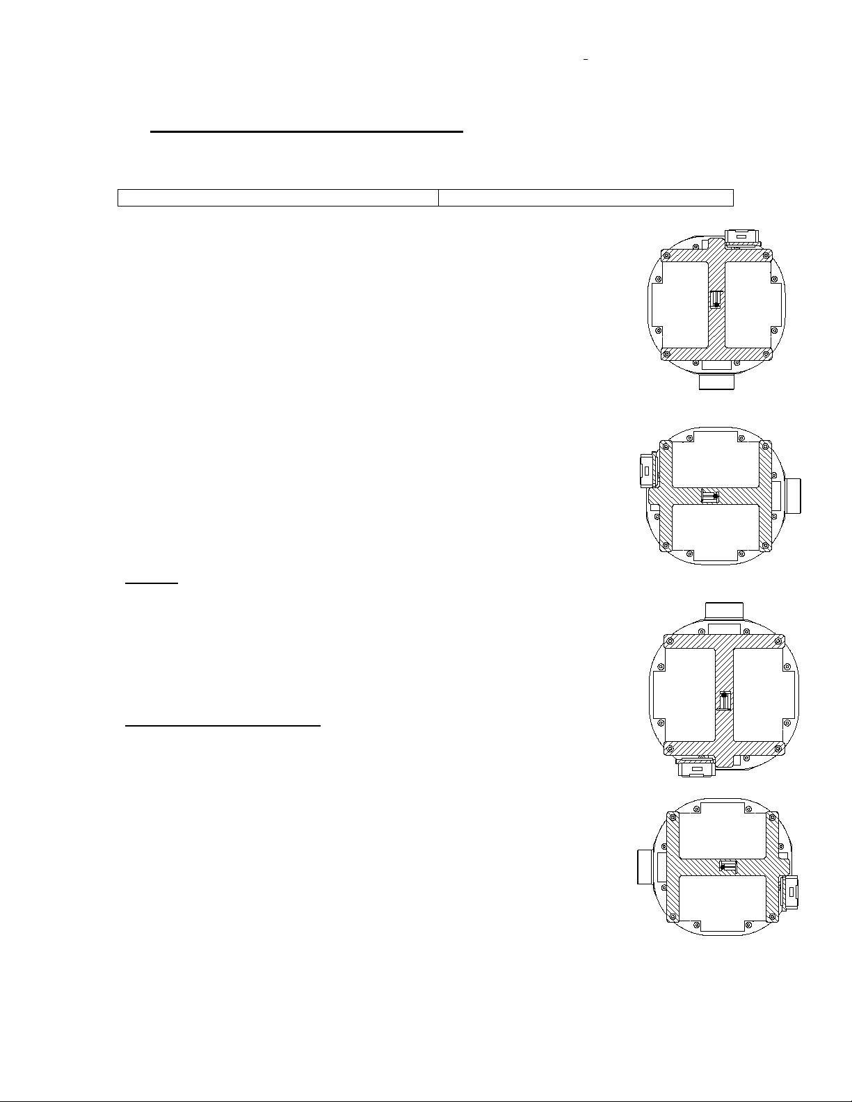
3.1. Mechanical Alignment
NIOBE®ALIGNMENT REPORT MP1
Date/Time: ____________________
Location: ____________________
Positioner P/N: ____________________
Positioner S/N: ____________________
Magnet S/N: ____________________
Alignment Fixture P/N: ____________________
Alignment Fixture S/N: ____________________
Calibration Certifier (name): ____________________
Calibration Certifier (signature): ____________________
Measured angles should be within 0.5°of commanded value
Tilt Axis:
0°Value: ____________________
+15°Value: ____________________
-15°Value: ____________________
Cover Distance (0°, +15°, -15°):
Distance to Reference (247.65mm+5/-1.5 mm): ______/_______/_______
Distance to Reference (457.2mm+5/-1.5 mm): ______/_______/_______
NIOBE®ALIGNMENT REPORT MP2
Date/Time: ____________________
Location: ____________________
0°Theta Position
90°Theta Position
180°Theta Position
270° Theta Position

985-006001 REV. G Effective Date: 03 June 2008
Stereotaxis, Inc. Page 8 of 43
Positioner P/N: ____________________
Positioner S/N: ____________________
Magnet S/N: ____________________
Alignment Fixture P/N: ____________________
Alignment Fixture S/N: ____________________
Calibration Certifier (name): ____________________
Calibration Certifier (signature): ____________________
Tilt Axis:
0°Value: ____________________
+15°Value: ____________________
-15°Value: ____________________
Cover Distance (0°, +15°, -15°):
Distance to Reference (247.65mm+5/-1.5 mm): ______/_______/_______
Distance to Reference (457.2mm+5/-1.5 mm): ______/_______/_______
Overall Alignment / Calibration Set-Up Pass: Fail:
Test Performed by:
Signature:___________________________________Date:____________
Print Name:_______________________________________

985-006001 REV. G Effective Date: 03 June 2008
Stereotaxis, Inc. Page 9 of 43
3.2. System Power On/Off and Emergency Stop
NOTE
If an X-ray system is not available at this time use the X-ray simulator for testing purposes.
No.
Test Description
Pass/Fail
Initials
1 Verify that the Emergency Stop buttons function
•While the system is powered on and operational depress the
emergency stop button in the control area and verify that the
red light labeled “E Stop Active” behind the left hand front door
of the Control cabinet illuminates and all motion of the MPs is
inhibited.
•While the system is powered on and operational depress the
emergency stop button on a tableside controller and verify that
the red light labeled “E Stop Active” behind the left hand front
door of the Control cabinet illuminates and all motion of the
MPs is inhibited.
P F
P F
2
Verify that the System/Positioner power on/off button functions
•While the system is powered on (the system/Positioner power
on light is lit) actuate the on/off switch by holding the button in
the OFF position (approx. 3 sec) until power is removed.
Verify that the on/off light is no longer lit, the red light labeled
“E Stop Active” behind the right hand front door of the Control
cabinet and the System Control/Remote Stop Unit** are
extinguished, and all motion of the MPs is inhibited.
•While the system is powered off (the system/Positioner power
on light is not lit) actuate the on/off switch to the on position.
Verify that the on/off light illuminates, the red light labeled “E
Stop Active” behind the right hand front door of the Control
cabinet and the System Control/Remote Stop Unit** are
extinguished, motion of the MPs is restored.
P F
P F
System/Positioner
power on when
illuminated (Green)
System/Positioner
power on/off
Emergency Stop
is activated when
illuminated (Red)
Emergency Stop
(E-Stop). Press to
halt all mechanical
motion.
Figure 1 – System Control / Remote Stop**
(001-005000-1 and 001-006000-1 configuration shown)

985-006001 REV. G Effective Date: 03 June 2008
Stereotaxis, Inc. Page 10 of 43
Figure 2 – Table Side Controller with Graphics (PM3.2 Version: 001-006000-1)**
** NOTE: E-Stop Button and/or E-Stop Light are not present on 001-005100-1 and 001-006100-1
configurations of Power Box or Table Side Controller.

985-006001 REV. G Effective Date: 03 June 2008
Stereotaxis, Inc. Page 11 of 43
3.3. System Homing
No.
Test Description
Pass/Fail
Initials
3
Verify that Homing of the system completes normally.
•Force a request for homing by powering off the system.
•Turn the system power back on and observe the message:
“The System Needs Homing – Press and Hold the Navigate
AP Button”.
•Press and hold the Navigate AP button on the tableside
controller until homing completes.
•Verify that the following icons are displayed during the Homing
process and all three yellow areas are blinking on right icon.
and
•Verify that the homing command completes normally by
observing the “Homing Complete” message on the monitors.
P F
P F
P F
P F
P F
3.4. PM3.2 System Movements, Stowed, Retracted, Navigate AP, Navigate RAO,
Navigate LAO and Navigate with Offset.
No.
Test Description
Pass/Fail
Initials
4
Verify the system will move to Navigate AP position from the Stowed
position.
•While the Positioner is in the Stowed position press and hold
Navigate AP position button:
on the tableside controller until the Positioner
reaches the Navigate position.
•Verify that the Navigate AP Position indicator:
is displayed on the control room and
procedure room monitors.
•Verify that while the Positioner is moving the green indicator
for the location the Positioner has been requested to move to
blinks during the move.
•Verify that the total time to move to Navigate position does
not exceed 60 seconds.
P F
P F
P F
P F
985-006001 REV. G Effective Date: 03 June 2008
Stereotaxis, Inc. Page 12 of 43
5
Verify the system will move to Stowed position from Navigate.
•While the Positioner is in the Navigate position press and
hold the stowed position button:
on the tableside controller until the Positioner
reaches the stowed position.
•Verify that the Stowed Position indicator:
is displayed on the control room and
procedure room monitors.
•Verify that while the Positioner is moving the green indicator
for the location the Positioner has been requested to move to
blinks during the move.
•Verify that the total time to move from Navigate to Stowed
does not exceed 30 seconds.
•Verify that the first 20oof movement, on Pivot axis, towards
stowed does not exceed 15 seconds.
P F
P F
P F
P F
P F

985-006001 REV. G Effective Date: 03 June 2008
Stereotaxis, Inc. Page 13 of 43
6
Verify the system will move to Retracted position from the Stowed
position.
•While the Positioner is in the Stowed position press and hold
the Navigate AP Button:
on the tableside controller until the Positioner
reaches the Retracted position and release Navigate AP
Button.
•Verify that the Retracted Position indicator:
is displayed on the control room and
procedure room monitors.
•Verify that while the Positioner is moving the green indicator
for the location the Positioner has been requested to move to
blinks during the move.
•Verify that the total time to move to Retracted position does
not exceed 60 seconds.
P F
P F
P F
P F
7
Verify the system will move to Navigate RAO and LAO positions from
the Retracted position.
•While the Positioner is in the Retracted position press and
hold Navigate position button:
for Navigate RAO
OR
for Navigate LAO on the tableside controller until
the Positioner reaches the Navigate position.
•Verify that the Navigate Position indicator:
for Navigate RAO
OR
for Navigate LAO is displayed on the control
room and procedure room monitors.
•Verify that while the Positioner is moving the green indicator
for the location the Positioner has been requested to move to
blinks during the move.
P F
P F
P F

985-006001 REV. G Effective Date: 03 June 2008
Stereotaxis, Inc. Page 14 of 43
8
Verify the system will move to Retracted position from the Navigate
position.
•While the Positioner is in the Navigate position press and
hold the Retracted position button:
and
on the tableside controller until the Positioner reaches the
Retracted position.
•Verify that the Retracted Position indicator:
is displayed on the control room and
procedure room monitors.
•Verify that while the Positioner is moving the green indicator
for the location the Positioner has been requested to move to
blinks during the move.
P F
P F
P F
9
•Now simultaneously hold the Image Transfer and the
appropriate Movement button to initiate the interlock override
condition and verify that the system will begin to move with
the Stow position button pressed.
+
P F

985-006001 REV. G Effective Date: 03 June 2008
Stereotaxis, Inc. Page 15 of 43
10
Verify that the C-Arm Collision Detection is operational between the
Niobe®and X-ray Systems.
•Pre-Condition: PM3CTRL not in Service Mode
•Place the Positioners in the Stowed position.
•Center Patient Table Laterally
•Move the C-Arm to RAO 35 degrees:
•Press the Navigate AP position button on the tableside
controller and verify that the system will NOT move to the
Navigate AP position (starts, but does not complete).
•Press the Navigate RAO position button on the tableside
controller and verify that the Positioner DOES move to the
Navigate RAO position.
•Press the Navigate LAO position button on the tableside
controller and verify that the Positioner does NOT move to
the Navigate LAO position (starts, but does not complete).
•Move the C-arm to the AP position.
•Press the Navigate LAO position button on the tableside
controller and verify that the Positioner DOES move to the
Navigate LAO position.
•Press the Manual Retract buttons for the Left then the Right
Pods to the Fully Retracted position.
•Now simultaneously hold the Image Transfer and any
Navigate button to initiate the interlock override condition
and verify that the system will NOT begin to move to the
Navigate position with the override buttons pressed.
•Move Table 75mm towards MP2.
•Press the Manual Advance button to for MP1 to the fully
extended position (max allowable).
•Press the Manual Advance button for MP2 until the Navigate
Position is achieved.
P F
P F
P F
P F
P F
P F
P F
P F
P F
P F
11 Verify that the system between locations Icon is displayed if the
tableside controller motion button is released prior to the movement
being completed when Pivoting.
•Verify that you observed the following icon when you release
the motion button prior to the requested position being
achieved.
P F

985-006001 REV. G Effective Date: 03 June 2008
Stereotaxis, Inc. Page 16 of 43
12
Verify that the Retracted Icon is displayed if the tableside controller
motion button is released prior to the movement being completed
when Tilting.
•Verify that you observed the following icon when you release
the motion button prior to the requested position being
achieved.
P F

985-006001 REV. G Effective Date: 03 June 2008
Stereotaxis, Inc. Page 17 of 43
3.5. Image Transfer from X-ray companion System
No.
Test Description
Pass/Fail
Initials
13
Verify that Valid Images can be transferred from the Siemens System
to the Niobe®System.
•Take one image, or use the X-ray simulator to send a file, of a
suitable phantom in the x-ray field with the RAO/LAO angle at
least 20o. Click the Transfer image button on the display.
•Verify that the system displays the image transfer in process
icon (same ICON as the transfer image, except arrow goes to
green and background goes to white)
•Verify that the images are displayed on the NavigantTM
monitor in two locations.
•Verify that the transfer time is in the range of 3-5 seconds.
•Take a second image, or use the X-ray simulator to send a
file, after moving the C-Arm through at least 40oof movement
RAO/LAO. Click the Transfer image button on the display.
•Verify that the system displays the image transfer in process
icon (same ICON as the transfer image, except arrow goes to
green and background goes to white)
•Verify that the image is displayed on the NavigantTM monitor in
two locations.
•Verify that the transfer time is in the range of 3-5 seconds.
P F
P F
P F
P F
P F
P F
P F
P F
14
Verify that the system will identify invalid images and not permit
magnetic navigation.
•Repeat test 13 but only move the RAO/LAO movement 39o,
or use the X-ray simulator to send a files, between transferring
the first image and the second image. Verify that the Images
Invalid Icon is displayed, which is a large yellow “X”.
P F
3.6. System Connectivity
No.
Test Description
Pass/Fail
Initials
15
Verify that the Niobe®system reports a loss of communication with the
X-ray System.
•With the system operational remove the Category 5 cable
from connector J2 on the Control cabinet. Verify that the
system reports a Missing Information icon.
P F
16
Verify that the Niobe®System reports a loss of communication with the
P F

985-006001 REV. G Effective Date: 03 June 2008
Stereotaxis, Inc. Page 18 of 43
Control cabinet.
•With the system operational remove the Category 5 cable
from connector on the front of each Galil motion controller in
the Control cabinet. Remove the connectors one at a time to
verify that either connector will result in lost connectivity. Verify
that the system displays the red “Cannot Communicate with
the Magnet Positioners” message.
985-006001 REV. G Effective Date: 03 June 2008
Stereotaxis, Inc. Page 19 of 43
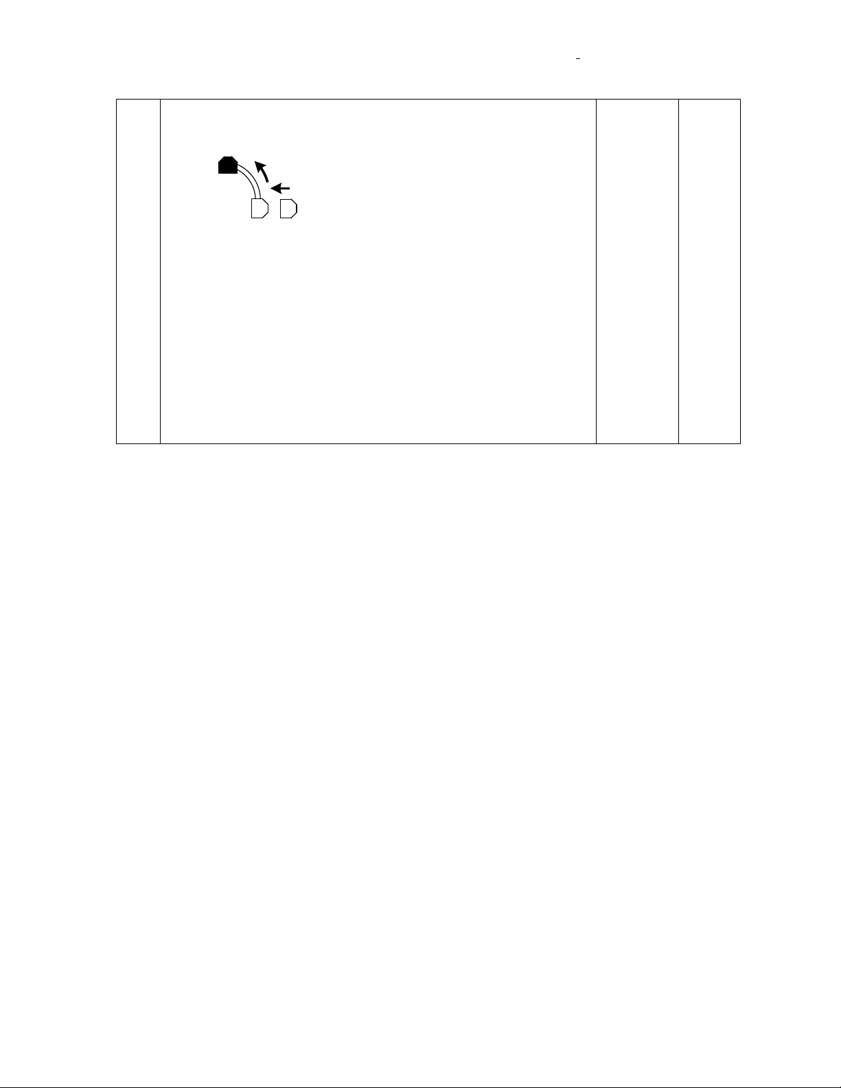
3.7. Image Brightness and Contrast Adjustments
No.
Test Description
Pass/Fail
Initials
17
Verify that the images can be adjusted for brightness and contrast on
the NWS system.
•Ensure that an image is displayed on the NWS Monitor.
•Select the Image Brightness and Contrast Adjust button on the
display.
•Verify that the cursor takes on a different shape.
•Adjust the brightness and contrast for both the RAO image
and the LAO image. Verify operation.
P F
P F
P F
3.8. Drawing Vectors, Apply Field, Reduce Field
No.
Test Description
Pass/Fail
Initials
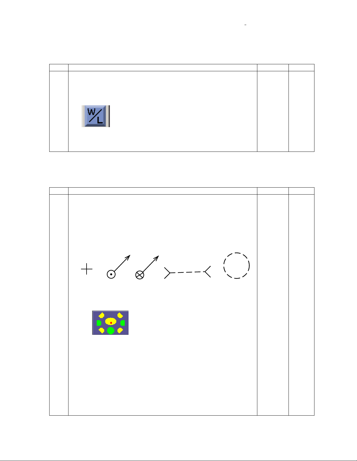
18
Verify that you can draw a vector on Valid Images and apply the field.
•Mount a catheter on the table in the navigation test apparatus.
Place the system in Navigate mode.
•Select device type.
•Select override
•Click on the “Direction Navigation Mode” icon.
•Acquire two valid images. Draw vectors for Cranial tip
orientation.
CURSOR VECTOR
(POINTING TOWARDS
YOU) CUE LINE
VECTOR
(POINTING AWAY
FROM YOU)
REDUCED FIELD
REGION
(APPROXIMATED)
•Click the apply field button on the display and observe the
catheter tip. Verify that the catheter tip is now in Cranial tip
orientation and the Applied Field icon is displayed.
OR appropriate Icon for Tilted Navigate position
with Field Applied.
•Verify that you observed the appropriate overlay information of
the screen while drawing vectors.
•Repeat for the following tip orientations:
oAnterior Tip Orientation
oPosterior Tip Orientation
oLeft Lateral Tip Orientation
oRight Lateral Tip Orientation
•Verify that the catheter tip orients in the expected direction.
P F
P F
P F
P F
P F
P F
P F
P F
P F
This manual suits for next models
1
Table of contents
Popular Laboratory Equipment manuals by other brands

CPAC
CPAC SteriDENT 300 operating instructions

Nepagene
Nepagene ELEPO21 instruction manual

Okolab
Okolab 158206046 installation guide

Endress+Hauser
Endress+Hauser Levelflex M FMP41C Safety instructions

Accuris
Accuris Smartdoc 2.0 Filter and user guide

Malmet
Malmet WDS1 Operation, maintenance and installation manual


