Sterlitech HP4750 Supplement
HP4750
ASSEMBLY & OPERATION
MANUAL


1. INTRODUCTION ........................................................................................ 1
2. BEFORE ASSEMBLY............................................................................... 2
3. STIRRED CELL ASSEMBLY .....................................................................3
4. OPERATION OF THE HP4750 STIRRED CELL .................................. 6
5. HP4750 EXAMPLE SYSTEM CONFIGURATION ............................... 8
6. ACCESSORY AND SPARE PART ORDERING INFORMATION ......... 9
7. O-RING CHEMICAL COMPATIBILITY...................................................10
8. RETURN MATERIAL ORDER PROCEDURE ......................................... 11
9. WARRANTY .............................................................................................. 11
10. TECHNICAL ASSISTANCE.................................................................... 11
APPENDIX 1: COMPRESSION CONNECTIONS ..................................... 12
APPENDIX 2: MEMBRANE CUTTING AND CONDITIONING .............. 13
APPENDIX 3: PRECONDITIONING MEMBRANE DISC FILTERS......... 14
APPENDIX 4: HP4750 BIBLIOGRAPHY .................................................. 15
APPENDIX 5: BENCH SCALE FILTRATION PRODUCTS...................... 16
CONTENTS

1. INTRODUCTION
The HP4750 Stirred Cell is a high-pressure, chemically resistant stirred cell that performs
a wide variety of membrane separations. With a maximum pressure rating of 1000 psig
(69 bar), the HP4750 Stirred Cell is ideally suited for reverse osmosis (RO) filtration,
nanofiltration (NF), ultrafiltration (UF), and microfiltration (MF) separations. Stainless steel
(316L) construction and chemically resistant components make the HP4750 Stirred Cell an
ideal choice to filter aqueous and non-aqueous solutions.
Table 1 outlines the operational parameters and technical specifications of the HP4750
Cell.
Prior to operating or servicing this device, this manual must be read and understood.
Table 1: HP4750 Features and Technical Specification
Parameter Description
Membrane Size 47-49 mm diameter (1.93 inches)
Active Membrane Area 14.6 cm2(2.26 in2)
Processing Volume 300 mL
Hold-Up Volume 1 mL
Maximum Pressure 69 bar (1000 psig)
Maximum Temperature 121 °C (250 °F) at 55 bars (800 psig)
Maximum Torque Setting for Nuts 20 ft-lbs
pH Range Membrane Dependant
Connections
Permeate Outlet ⁄ inch diameter 316L SS tubing
Pressure Inlet ¼ inch FNPT
Wetted Materials of Construction
Cell Body 316L Stainless Steel
O-Rings Buna-N, others available as options
Gasket Buna-N, others available as options
Stir Bar PTFE-coated magnet
Dimensions
Cell Diameter 5.1 cm (2.0 inches)
Cell Height 22.4 cm (10.0 inches)
Autoclavable Ye s
Sterlitech Corporation | HP4750 Cell Manual
1

2. BEFORE ASSEMBLY
HP4750 Cell Manual | Sterlitech Corporation 2
1. Stainless steel cell body
2. Cell Top
3. Cell Bottom
4. Cell Top Coupling
5. Cell Bottom Coupling
6. Porous Stainless Steel Membrane Support Disk
7. 2 O-rings
8. Top Gasket
9. Permeate Tube
10. Stir Bar Assembly
11. Stir Bar Retriever
Verify that the stirred cell was shipped complete, intact, and undamaged. The complete
set of stirred cell parts is found in Figure 1 below.
Figure 1: HP4750 Components

Sterlitech Corporation | HP4750 Cell Manual
3
To assemble the HP4750 stirred cell:
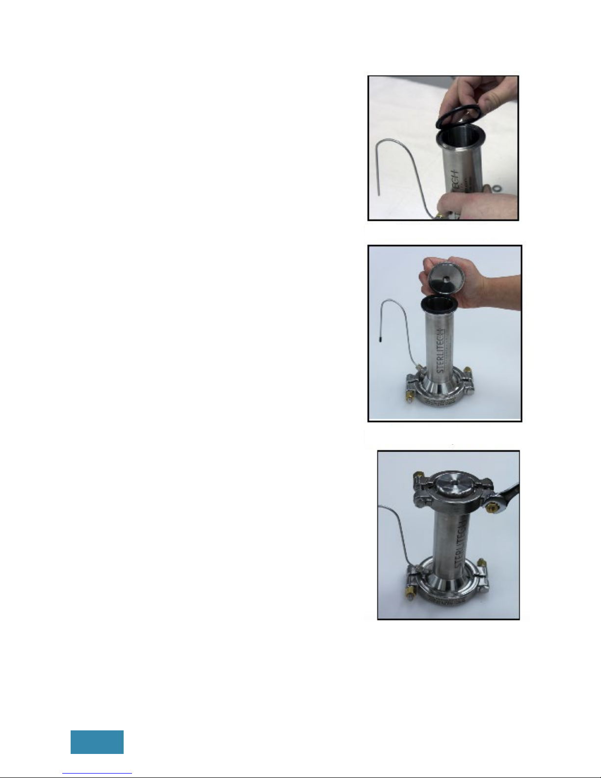
1. Wet the O-rings with a small amount of
water or the fluid to be processed.
Note: HP4750 Stirred Cells are shipped
with Buna O-rings and gaskets by default;
other materials such as Viton and PTFE are
available as options. Table 3 outlines O-ring
and gasket material compatibility.
2. Insert the O-rings in the bottom of the cell
body (Photo 1 & 2). Check to be certain
that the O-rings it properly in the grooves.
3. Place a piece of precut membrane over
the center O-ring. The membrane should
be installed with the active side toward
the cell reservoir. In general, membranes
coated on substrate have a shiny, active
side and a dull, substrate side (Photo 3).
4. Place the stainless steel porous membrane
support disk on top of the membrane to
hold the membrane in place (Photo 4).
Note: If you cut your own membranes, the
stainless steel porous disk can be used as a
template. See Appendix 3 for more details.
3. STIRRED CELL ASSEMBLY
After verifying that all of the necessary components were shipped and present, you can
begin the assembly of the stirred cell.
Photo 1: Outer Ring Insertion
Photo 2: Inner Ring Insertion
Photo 3: Membrane Filter Insertion
Photo 4: Membrane Support Disc Insertion

HP4750 Cell Manual | Sterlitech Corporation 4
5. Fit the cell bottom onto the cell body,
aligning the circular groove with the
circular ridge on the bottom of the cell
body (Photo 5).
6. Use the 3-inch high pressure coupling to
clamp the cell bottom to the cell body.
Tighten the high pressure coupling with
16 foot pounds of torque for 1000 psig (69
bar) operation (Photo 6).
7. Insert Permeate Tube into side of cell
body, tighten using a wrench (Photo 7).
Note: The HP4750 uses Swagelok connection
fittings. More detailed instructions, information
and images of the fittings can be found in
Appendix 1.
8. Insert the Stir bar assembly by lowering
it into the cell with the stir bar retriever
(Photo 8). Figure 2 shows the correct
position of the Stir Bar Assembly. After the
assembly is in place, pour the solution to
be filtered into the Cell Body.
Figure 2: Proper Stir Bar Position
Photo 5: Cell Bottom Assembly
Photo 6: Bottom Clamp Assembly
Photo 7: Permeate Tube Installation
Photo 8: Stir Bar Insertion w/ Stir Bar Retriever
Sterlitech Corporation | HP4750 Cell Manual
5
9. Insert the gasket on the top of the Cell
Body, making sure it fits properly in the
grooves (Photo 9).
10. Use the 2-inch high pressure coupling to
clamp the cell top to the cell body (Photo
10). Tighten the high pressure coupling
with 16 foot pounds of torque for 1000 psig
(69 bar) operation (Photo 11). After both
clamps are properly attached, the HP4750
Stirred Cell should be centered on top of a
magnetic stirrer.
Photo 9: Gasket Installation
Photo 10: Cell Top Attachment
Photo 11: Cell Top Clamp
HP4750 Cell Manual | Sterlitech Corporation 6
4. OPERATION OF THE HP4750 STIRRED CELL
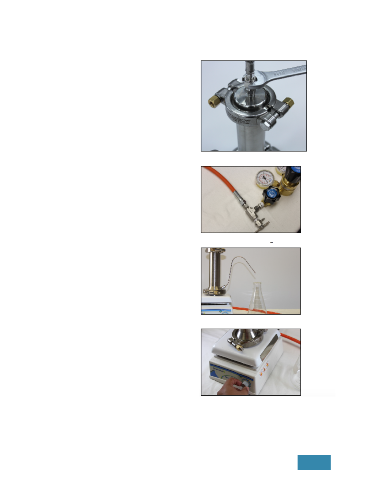
1. Attach a high pressure hose (sold
separately, Sterlitech Part Number: 1151427)
to the fitting on the Cell Top (Photo 12).
2. Connect the other end of the hose to the
pressure regulator assembly on the inert
gas supply or the compressed air supply.
The compressed air or inert gas source
selected will determine pressure regulator
(sold separately, Sterlitech Part Number:
1144026 style and pressure requirements
(Photo 13).
3. Place a Permeate Collection Vessel (user
supplied) under the Permeate Tube (Photo
14).
4. Turn on the magnetic stirrer (sold
separately, Sterlitech Part Number 1144030
or 1144031) to start the motion of the Stir
Bar Assembly (Photo 15).
5. Begin filtration by gradually pressurizing
the HP4750 Stirred Cell, checking for
leaks. Foreign material on the surface of
the seals and insucient tightening of
the clamps are most common causes for
leakage.
Note: Preconditioning the membranes before
use will ensure consistent performance. See
Appendix 3 for more details.
Photo 12: High Pressure Hose Attachment
Photo 13: Pressure Regulator Connection
Photo 14: Permeate Collection Vessel
Photo 15: Magnetic Stirrer
Sterlitech Corporation | HP4750 Cell Manual
7
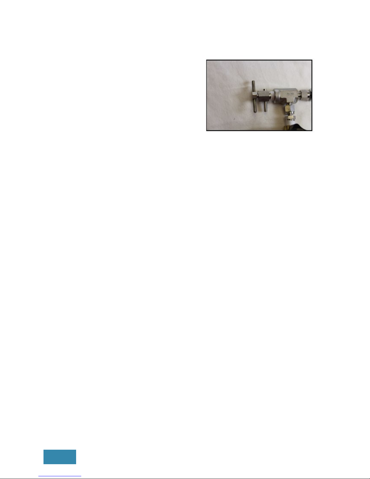
6. Upon completion of filtration, turn o
the pressure source and depressurize
the unit by the pressure relief valve
(sold separately, Sterlitech Part Number:
1155893) (Photo 16).
CAUTION: Do not depressurize the HP4750
Stirred Cell by loosening the couplings.
7. Once it is depressurized and empty, the
HP4750 Stirred Cell can be cleaned with
a variety of cleaners, including detergents,
solvents, caustic, acid, enzyme cleaners,
etc.
Note: Choice of the appropriate cleaning
regime should also consider the compatibility
of the gasket and O-ring material. A section of
O-ring chemical compatibilities is presented
on page 10.
Photo 16: Pressure Relief Valve

HP4750 Cell Manual | Sterlitech Corporation 8
5. HP4750 EXAMPLE SYSTEM CONFIGURATION
Figure 3 illustrates the typical configuration of a standard HP4750 Stirred Cell System. The
drawing shows the three major components of the system: the Cell Body with removable
top and bottom, Stir Bar Assembly, and Standard Coupling.
Figure 3: HP4750 Stirred Cell System Schematic

Sterlitech Corporation | HP750 Cell Manual
9
6. ACCESSORY AND SPARE PART ORDERING INFORMATION
Accessories and spare parts for the HP4750 can be ordered by calling Sterlitech
Corporation at 1-877-544-4420 or by visiting www.sterlitech.com.
Product Shipping Weight Ordering Number
HP4750 Stirred Cell, for operation to 69
bar (1000 psig) 3.8 kg (8 lbs) HP4750
Accessories
Pressure Regulator Assembly, 6.9-69 bar
(100-1000 psig) 2.3 kg (5 lbs) 1144026
Pressure Bleed Valve, 172 bar (2500
psig) 0.1 kg (0.25 lb) 1155893
High Pressure Hose, 183 cm (72 inch) 0.7 kg (1.5 lbs) 1151427
PTFE O-ring/Gasket Kit 0.5 kg (0.1 lb) 1144028
Viton O-ring/Gasket Kit 0.5 kg (0.1 lb) 1144029
PTFE Encapsulated Viton O-ring/Gasket
Kit 0.5 kg (0.1 lb) 1144027
Buna O-ring/Gasket Kit 0.5 kg (0.1 lb) 1144034
EPDM O-ring Gasket Kit 0.5 kg (0.1 lb) 1144036
Magnetic Stirring Plate
115 VAC 60 Hz 2.3 kg (5 lbs) 1144030
230 VAC 50 Hz 2.3 kg (5 lbs) 1144031
Spare Parts
Cell Top 0.1 kg (0.25 lb) 1143891
Cell Body 1.4 kg (3 lbs) 1149782
Cell Bottom 1.4 kg (3 lbs) 1143073
Porous Support Disk 0.1 kg (0.25 lb) 1114910
Stir Bar Assembly 0.1 kg (0.25 lb) 1143109
Membrane Packs
Visit www.sterlitech.com for membrane ordering information.
Table 2: Accessory and Spare Part Ordering Information

HP4750 Cell Manual | Sterlitech Corporation 10
7. O-RING CHEMICAL COMPATIBILITY
The following O-ring and gasket compatibility chart (Table 3) is provided as an aid in selecting
a specific synthetic rubber compound for a particular application situation. Operating
conditions and environment must also be considered in determining the media suitability.
For recommendations regarding fluids not listed, consult Sterlitech. The recommendations
represent compatibility of materials only and do not necessarily constitute a recommendation
for use in a specific application.
Table 3: O-Ring Chemical Compatibility Chart
Code Compound Temperature
BN Buna-N -40 to 120 °C (-40 to 250 °F)
EP Ethylene-Propylene -50 to 150 °C (-65 to 300 °F)
VViton -30 to 205 °C (-20 to 400 °F)
Media (Liquid or Gas) Code Media (Liquid or Gas) Code
Acetic Acid, Glacial EP Glycols EP
Acetone EP Grease and Oils BN
Aluminum Salts BN Glycols EP
Ammonium Hydroxide EP Hydrochloric Acid EP
Ammonium Salts BN Hydrofluoric Acid EP
Amyl Alcohol EP Hydrogen Peroxide V
Aniline Dyes EP Kerosene BN
Aromatic Fuel - 50% VLinseed Oil BN
Benzene VMethyl Ethyl Ketone EP
Bleach Liquor EP Mineral Oils BN
Butanol (Butyl Alcohol) BN Naphthas V
Butyl Cellosolve EP N-Hexane BN
Carbon Disulfide VOctyl Alcohol EP
Carbon Tetrachloride VOrganic Ester EP
Cellosolve EP Peanut Oil BN
Chlorinated Solvents VPhenol V
Crude Oil VPyridine Oil EP
Cutting Oil VSewage BN
Decane BN Sodium Acetate EP
Denatured Alcohol BN Sodium Chloride BN
Detergent, Water Solution BN Stoddard Solvent BN
Diesel Oil BN Sulfuric Acid V
Diethylene Glycol EP Tannic Acid BN
Dry Cleaning Fluids VTertiary Butyl Alcohol V
Ethyl Alcohol BN Titanium Tetrachloride V
Ethyl Hexanol BN Transmission Fluid BN
Ethylene Glycol EP Trioctyle Phosphate EP
Fatty Acids VVarnish V
Fatty Oil BN Water (Demineralized) BN

8. RETURN MATERIAL AUTHORIZATION
If materials are to be returned to Sterlitech for repair, evaluation, or warranty consideration,
a Return Material Authorization (RMA) number and form must be obtained from Sterlitech
prior to the return. Contact Sterlitech’s Customer Service Department for these forms.
The form must be completed and returned with the material. Be sure to include a
complete, detailed written reason for the return. Also, include serial numbers, installation
and removal dates, and any other pertinent information that is available. HP4750 Cells
have a serial number imprinted on the cell bottom.
Indicate the proposed disposition of the material, and reference the RMA number on all
packages or cartons. All material must be shipped to Sterlitech with freight prepared by
the customer.
9. WARRANTY
The following is made in lieu of all other warranties expressed or implied. Sterlitech
Corporation guarantees equipment to be free from defects in material and workmanship
when operated in accordance with written instructions for a period of one year from
receipt. Parts not manufactured by Sterlitech are covered by their manufacturer’s
warranties, which are normally for one year.
Manufacturers and Seller’s only obligation shall be to issue credit against the purchase
or replacement of equipment proved to be defective in material or workmanship. Neither
manufacturer nor seller shall be liable for any injury, loss or damage, direct or indirect,
special or consequential, arising out of the use of, misuse, or the inability to use such
product.
The information contained herein is based on technical data and tests, which we believe
to be reliable, and is intended for use by persons having technical skill at their discretion
and risk. Since conditions of use are outside Sterlitech’s control, we can assume no
liability whatsoever for results obtained or damages incurred through the application of the
data presented.
This information is not intended as a license to operate under, or a recommendation to
infringe upon, any patent of Sterlitech or others covering any material or use.
The foregoing may not be altered except by a written agreement signed by ocers of the
manufacturer.
10. TECHNICAL ASSISTANCE
Please contact us if you have any questions or technical inquiries about our products by
calling Sterlitech Corporation at 1-877-544-4420 or by visiting www.sterlitech.com.
Sterlitech Corporation | HP750 Cell Manual
11
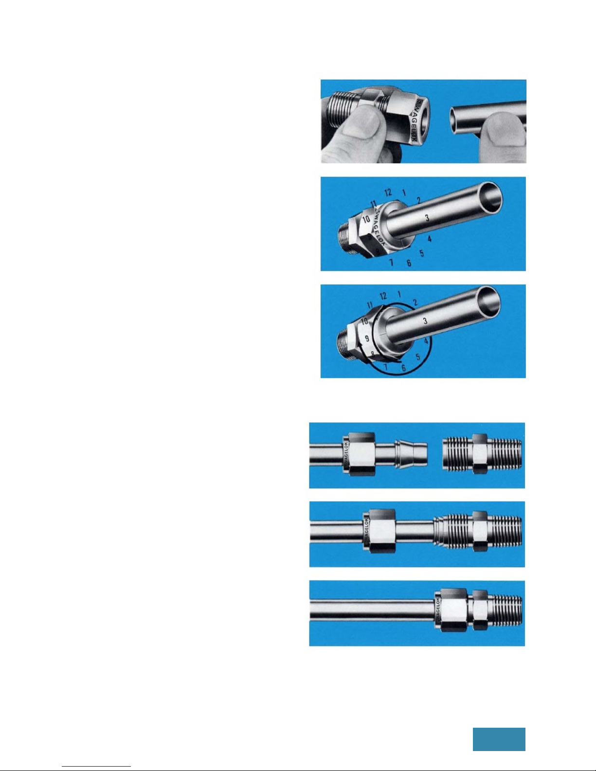
APPENDIX 1: COMPRESSION CONNECTIONS
To install Compression Tube Fittings:
1. Insert the tubing into the Compression
tube fitting. Make sure that the tubing rests
firmly on the shoulder of the fitting and that
the nut is finger-tight.
2. Scribe the nut at the 6 o’clock position. By
scribing the nut at the 6 o’clock position as
it appears to you, there will be no doubt as
to the starting position.
3. Hold the fitting body steady with a backup
wrench and tighten the nut 1¼ turns. Watch
the scribe mark, make one complete
revolution and continue to the 9 o’clock
position. When the nut is tightened to the
9 o’clock, you can easily see the fitting has
been tightened properly.
Compression connections can be
disconnected and retightened many times.
To retighten the Compression connection:
1. Start with the disconnected fitting.
2. Insert tubing with preswaged ferrules into
fitting body until front ferrule seats.
3. Tighten the nut by hand. Rotate nut to
the original position with a wrench. An
increase in resistance will be encountered
at the original position. Then tighten
slightly with the wrench.
HP4750 Cell Manual | Sterlitech Corporation 12
Sterlitech Corporation | HP750 Cell Manual
13
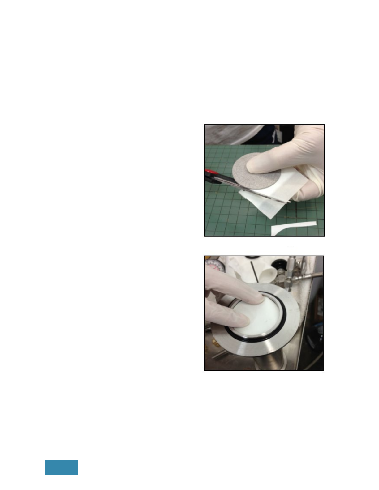
APPENDIX 2: MEMBRANE CUTTING AND CONDITIONING
Sterlitech oers a wide variety of membranes that have been pre-cut for use with the
HP4750. However, if you need cut your own membrane for use with the HP4750 Stirred
Cell, then you will need the following items:
• The porous stainless steel support disk, which will serve as the template
• The membrane sheet to be cut
• A pair of sharp scissors
• A pair of latex gloves
To cut a membrane disk filter for the HP4750:
1. Take the porous stainless support disk and
place the membrane sheet against it. Be
sure to have the latex gloves on to avoid
contaminating the membrane surface.
2. Cut along the edge of the template with
the scissors. Hold the scissors at an angle
towards the center of the template to
avoid undertrimming (Photo 17). Once
finished, the membrane should sit perfectly
flat on supports without any bending and
extend outside of the inner O-ring to avoid
leakage (Photo 18).
Photo 17: Membrane Cutting
Photo 18: Membrane Fitting

HP4750 Cell Manual | Sterlitech Corporation 14
APPENDIX 3: PRECONDITIONING MEMBRANE DISC FILTERS
To precondition the membrane:
1. Load the membrane into the HP4750 Stirred Cell.
2. Fill the stirred cell with deionized water and pressurize the cell. The temperature of the
water and the pressure used should be the same as the temperature and pressure that
will be used in the actual trials.
3. Run deionized water through the cell until flux is relatively constant. After a few
minutes, flux through the membrane will stabilize following a sharp change.
4. Release pressure, discard the deionized water and fill the tank with desired feed
sample.

APPENDIX 4: HP4750 BIBLIOGRAPHY
The following studies utilized the HP4750 Stirred Cell in their method and are listed here
to illustrate the potential applications for the HP4750. These studies are good references
for understanding the operation of the HP4750 Stirred Cell.
TITLE ABSTRACT FULL CITATION
Modeling of the retention
of atrazine and dimethoate
with nanofiltration
The HP4750 stirred cell
was used to test which
nanofiltration
membrane
(NF90, NF200, NF270,
and DK) worked best
at removing pesticides
from water.
A.L. Ahmad, L.S. Tan, S.R. Abd. Shukor.
Modeling of the retention of atrazine and
dimethoate with nanofiltration. Chemical
Engineering Journal, Volume 147, Issues
2–3, 15 April 2009, Pages 280–286.http://
dx.doi.org/10.1016/j.cej.2008.07.015
Eects of palm oilbased
fatty acids on fouling of
ultrafiltration membranes
during the clarification of
glycerin-rich solution
In this study, the
HP4750 cell was
used to examine the
membrane-binding
properties fatty acids
with polyethersulfone
(PES) and
polyvinylidenefluoride
(PVDF) ultrafiltration
membranes.
Indok Nurul Hasyimah Mohd Amin, Abdul
Wahab Mohammad, Mastura Markom,
Leo Choe Peng. Eects of palm oil-based
fatty acids on fouling of ultrafiltration
membranes during the clarification
of glycerin-rich solution. Journal of
Food Engineering, Volume 101, Issue 3,
December 2010, Pages 264–272. http://
dx.doi.org/10.1016/j.jfoodeng.2010.07.006
Preparation and
characterization of
a neutrally charged
antifouling nanofiltration
membrane by coating
a layer of sulfonated
poly(ether ether ketone)
on a positively charged
nanofiltration membrane
The HP4750 stirred
cell was used to test
the antifouling and
separation capability
of a specially
prepared, electrically
neutral nanofiltration
membrane.
Chaoyi Ba, James Economy. Preparation
and characterization of a neutrally
charged antifouling nanofiltration
membrane by coating a layer of
sulfonated poly (ether ether ketone)
on a positively charged nanofiltration
membrane. Journal of Membrane
Science, Volume 362, Issues 1–2, 15
October 2010, Pages 192–201. http://
dx.doi.org/10.1016/j.memsci.2010.06.032
Synthesis and
characterization of a
carbon nanotube/polymer
nanocomposite membrane
for water treatment
The HP4750 was used
to characterize the
separation properties
of carbon composite
membrane at 2.9, 3.9
and 4.9 MPa.
Hosam A. Shawky, So-Ryong Chae,
Shihong Lin, Mark R. Wiesner. Synthesis
and characterization of a carbon
nanotube/polymer nanocomposite
membrane for water treatment.
Desalination, Volume 272, Issues 1–3,
3 May 2011, Pages 46–50. http://dx.doi.
org/10.1016/j.desal.2010.12.051
Sterlitech Corporation | HP750 Cell Manual
15

APPENDIX 5: STERLITECH BENCH SCALE FILTRATION PRODUCTS
Discoverer Innovator Explorer Developer Investigator
Filter Holder
HP4750(X) CF016 CF042 Sepa 1812
Membrane Active
Area
14.6 cm2(2.26 in2) 20.6 cm2(3.2 in2) 42 cm2(6.5 in2)140 cm2(24 in2)0.27-0.46 m2(3-5 ft2)
Typical Permeate
Flux
30-300 LMH
(17.6-176 GFD)
30-300 LMH
(17.6-176 GFD)
30-300 LMH
(17.6-176 GFD)
30-300 LMH
(17.6-176 GFD)
30-300 LMH
(17.6-176 GFD)
Typical Permeate
Flow Rate
(per Cell)
1.5-15 mL /min 1-10 mL /min 2-20 mL/min 7-70 mL/min 350-2,300 mL/min
System Capacity
0.7-7 L /day
(0.2-2 GPD)
1.5-15 L/day
(0.4-4 GPD)
3-30 L/day
(0.5-5 GPD)
10-100 L/day
(2.6-26 GPD)
194-1,940 L/day
(51-510 GPD)
Min. Batch Volume
(per Cell)
300 mL 3.7 L (1 gal) 3.7 L (1 gal) 3.7 L (1 gal) 15 L (4 gal)
Max. Pump
Capacity
N/A 6.8 LPM (76 bar)
1.8 GPM (1,100 psi)
6.8 LPM (76 bar)
1.8 GPM (1,100 psi)
6.8 LPM (76 bar)
1.8 GPM (1,100 psi)
6.8-38 LPM (76 bar)
1.8-10 GPM (1,100 psi
)
Cell Material
SS316, HastelloyTM PTFE, Delrin, Acrylic,
SS316, HastelloyTM
PTFE, Delrin, Acrylic,
SS316, HastelloyTM
Acrylic, SS316, HastelloyTM
SS316
Max. Operating
Pressure
HP4750: 69 bar (1,000 psi)
HP4750X: 172 bar (2,500 psi)
PTFE/Acrylic: 27.6 bar (400 psi)
Delrin/SS316/HastelloyTM:
69 bar (1,000 psi)
PTFE/Acrylic: 27.6 bar (400 psi)
Delrin/SS316/HastelloyTM:
69 bar (1,000 psi)
Acrylic: 27.6 bar (400 psi)
SS316/HastelloyTM:69 bar
(1,000 psi)
41.4 bar (600 psi)
Filtration Mode(s)
Dead-End Stirred Cell Cross Flow, Forward Osmosis Cross Flow, Forward Osmosis Cross Flow, Forward Osmosis Cross Flow
HP4750 Cell Manual | Sterlitech Corporation 16

NOTES:
Table of contents
Other Sterlitech Laboratory Equipment manuals


