DMT 320A User manual

USER GUIDE, VOL.2.1
SINGLE WIRE MYOGRAPH SYSTEM - 320A

SINGLE WIRE MYOGRAPH 320A
USER GUIDE

CONTENTS
Chapter 1 - Single Wire Myograph overview........................................................................................................................................................................3
Chapter 2 - Setting up the Single Wire Myograph .............................................................................................................................................................4
2.1 Adjustment of supports.....................................................................................................................................................................4
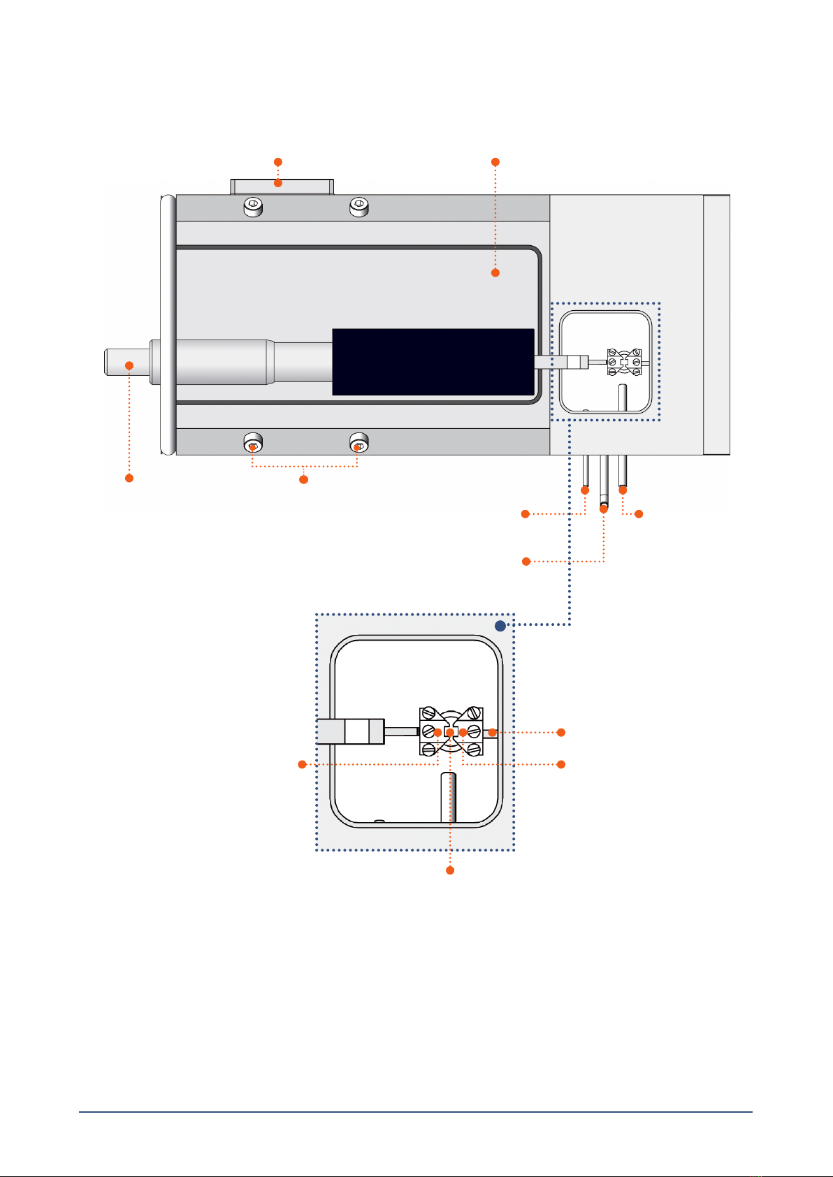
2.2 Force transducer calibration.............................................................................................................................................................5
Chapter 3 - Experimental set-up ..............................................................................................................................................................................................6
3.1 Mounting protocol for small arteries................................................................................................................................................6
3.1.1 Mounting step one ......................................................................................................................................................................6
3.1.2 Mounting step two ......................................................................................................................................................................7
3.1.3 Mounting step three ...................................................................................................................................................................7
3.1.4 Mounting step four......................................................................................................................................................................8
3.1.5 Mounting step ve.......................................................................................................................................................................8
3.1.6 Mounting step six........................................................................................................................................................................9
3.1.7 Mounting step seven...................................................................................................................................................................9
3.2 Normalization ....................................................................................................................................................................................9
3.2.1 Principles of the normalization procedure ............................................................................................................................. 10
3.3 Standard start................................................................................................................................................................................. 10
3.3.1 Principles of the standard start procedure ............................................................................................................................ 10
3.4 Endothelium function..................................................................................................................................................................... 11
3.4.1 Principles of checking endothelium function......................................................................................................................... 11
3.5 In vitro experiment 1: Noradrenaline contractile response......................................................................................................... 12
3.5.1 Background .............................................................................................................................................................................. 12
3.5.2 Protocol..................................................................................................................................................................................... 12
3.6 In vitro experiment 2: Acetylcholine relaxation curve .................................................................................................................. 13
3.6.1 Background .............................................................................................................................................................................. 13
3.6.2 Protocol..................................................................................................................................................................................... 13
Chapter 4 - Cleaning and Maintenance .............................................................................................................................................................................. 14
4.1 Cleaning the Single Wire Myograph .............................................................................................................................................. 14
4.2 Maintenance of the force transducer ........................................................................................................................................... 15
4.2.1 Checking force transducer ...................................................................................................................................................... 15
4.2.2 Force transducer replacement................................................................................................................................................ 16
4.4 Maintenhance of the linear slide .................................................................................................................................................. 17
4.3 Changing the Single Wire Myograph window glass...................................................................................................................... 17
Appendix 1 - Buer recipes ..................................................................................................................................................................................................... 18
Appendix 2 - Normalization theory ...................................................................................................................................................................................... 20
Appendix 3 - Reading a millimetre micrometer............................................................................................................................................................... 22
Notes................................................................................................................................................................................................................................................ 23

4CHAPTER 1
CHAPTER 1 SINGLE WIRE MYOGRAPH OVERVIEW
Port for connection to Wire Interface
Myograph jaw connected
to force transducer
Myograph jaw connected
to micrometer
Micrometer
Suction pipe for connection
to vacuum pump
Pipe for gas supply Pipe for lling the chamber
(using the 40 mm funnel)
Force transducer pin
Figure 1.1 Single Wire Myograph with close-up of chamber
Transducer house
Allen screws for ne alignment of the jaws
(2 on each side)
Window at the bottom of the Myograph chamber
for imaging (under the wire jaws)

5SINGLE WIRE MYOGRAPH SYSTEM - 320A - USER GUIDE
B
A E
CD
Figure 2.1 Illustration of screws for adjusting supports and horizontal adjustment
CHAPTER 2 SETTING UP THE SINGLE WIRE MYOGRAPH
2.1 Adjustment of supports
A successful mounting of any kind of tubular tissue segment in the Single Wire Myograph is to a high extent dependent on per-
fectly matching supports. The supports are matched prior to the shipment but daily use of the Single Wire Myograph and greasing
of the transducer pinhole will over time create a need for an adjustment of the supports.
NOTE
THE TRANSDUCERS ARE FRAGILE AND SENSITIVE TO MECHANICAL STRAIN. BE VERY CAUTIOUS NOT TO PUT STRAIN ON THE
TRANSDUCER WHEN CHANGING OR ADJUSTING THE MOUNTING SUPPORTS. IN ADDITION, VERY LITTLE FORCE SHOULD BE
APPLIED TO THE SCREWS IN ORDER TO AVOID BREAKING THE THREADS.
Adjustment of the supports is performed using the following step-by-step procedure. The procedure is illustrated in gure 2.1.
1. Carefully loosen screw “E” on the top of the support connected to the force transducer. Align the horizontal support and
carefully tighten the screw again.
2. Loosen screw “D” on the top of the support connected to the linear slide. Align the horizontal support matching the force
transducer connected support as carefully as possible and gently tighten the screw again.
3 Loosen screw “C” on the linear slide to roughly match the linear slide support to the force transducer support in the horizon-
tal plane. Tighten the screw before proceeding with step 4.
4. The plate “B” on which the linear slide is mounted is balanced on top of a small stainless steel ball making it possible to
nely adjust the linear slide support in all vertical and horizontal planes using the four Allen screws “A”. Use the four Allen
screws to make the nal horizontal (see arrow in gure 2.1) and vertical (see arrow in gure 2.2) adjustments to match the
linear slide support to the force transducer support. The correct matching of the supports is illustrated in gure 2.3.
IMPORTANT
AVOID CONTINUOUSLY TIGHTENING THE ALLEN SCREWS DURING THE FINAL ADJUSTMENTS: LOOSEN THE ALLEN SCREW
PLACED DIAGONALLY TO THE ALLEN SCREW BEING TIGHTENED, OTHERWISE THERE IS A HIGH RISK OF DAMAGING THE
SINGLE WIRE MYOGRAPH FRAME.

6
Figure 2.2 Illustration of vertical adjustment
Figure 2.3 Illustration of correctly aligned supports for small vessels (left) and
incorrectly aligned supports (middle and right)
CHAPTER 2
2.2 Force transducer calibration
DMT recommends that the Single Wire Myograph is force calibrated at least once every month. DMT also recommends that the
Single Wire Myograph is force calibrated every time the system has been moved or has not been used for a long period of time.
See the force calibration procedure in chapter 3.7.1 in Wire Myograph Systems - User Manual.

7SINGLE WIRE MYOGRAPH SYSTEM - 320A - USER GUIDE
CHAPTER 3 EXPERIMENTAL SETUP
This chapter contains experimental set-up for the Single Wire Myograph. For dissection of a vessel, please see Procedures for
investigations of small vessels using a small vessel Myograph by M.J. Mulvany.
3.1 Mounting protocol for small arteries
The procedure involves attaching the mounting wires to jaws which are in turn mounted on the force transducer. This force trans-
ducer is capable of measuring with a sensitivity of about 0.01 mN (1 mg), but can be damaged if the applied force exceeds about
1 N (100 g). Therefore care must be taken to avoid pressing the jaws too hard together. A movement of ~20 µm after they have
touched is sufficient to hold the wires clamped.
3.1.1 Mounting step one
• Cut lengths of 40 μm wire ~2.2 cm long. Mount one wire on left-hand jaw of the Single Wire Myograph as follows.
• Holding wire at far end, place centre of wire between jaws and screw jaws together so that the wire is clamped (gure 3.1 A).
NOTE
DO NOT CLOSE THE JAWS TOO HARD AGAINST EACH OTHER.
• Bend the far end of the wire towards the left, and wrap it around under xing screw, so the wire is wound clockwise: tighten-
ing the screw will then tighten the wire. This procedure should result in the wire being clamped between the jaws and with
near end of wire pointing towards operator (gure 3.1 B-C).
• Fill the Single Wire Myograph chamber with PSS (at room temperature). See appendix 1 for example of buffer recipes.
Figure 3.1 A, B and C Mounting step 1
ABC

8
3.1.2 Mounting step two
• Using forceps to hold the handle segment, transfer excised vessel from Petri dish to Single Wire Myograph chamber. Hold
the vessel as close to the proximal end as possible and try to mount the vessel onto the wire.
• If the lumen is shut, try one of the following possibilities:
1. Use the wire to gently push the lumen open (blood streaming out is a good sign).
2. Hold excised vessel about 3 mm from the cut end with one set of forceps and use the other forceps to squeeze the blood
remaining in lumen out through the cut end.
• Pull the proximal end of the excised vessel segment along the wire such that the vessel segment acts as its own feeder to be
feed into the wire into the vessel (gure 3.2 A-C). Be careful not to stretch the vessel segment if the end of the wire catches
the vessel wall.
3.1.3 Mounting step three
• Once the vessel segment is threaded onto the wire, catch the free end of the wire (nearest you) with the forceps and move
the jaws apart.
• While controlling the movement of the wire with the forceps, use the other forceps to gently pull the vessel segment along
the wire until the area of interest is situated in the gap between the jaws. The near end of the vessel segment shall lie about
0.1 mm inside the jaw gap to insure no point of contact (gure 3.3 A).
• Still controlling the free wire end with the forceps, move the jaws together to clamp the wire and in one movement secure
the wire under the near xing screw on the left-hand jaw. Again in a clockwise direction so that tightening the screw also
tightens the wire (gure 3.3 B).
Figure 3.3 A and B Mounting step 3
ABC
B
Figure 3.2 A, B and C Mounting step 2
CHAPTER 3

9SINGLE WIRE MYOGRAPH SYSTEM - 320A - USER GUIDE
Figure 3.5 A, B and C Mounting step 5
ABC
ABC
Figure 3.4 A, B and C Mounting step 4
3.1.5 Mounting step ve
• Move the jaws apart (gure 3.5 A). Take a second wire holding it about one third down from the far end using forceps. Align
the wire parallel with the vessel segment such that the wire can be passed into the far end of the lumen. Gently feed the
wire through the lumen of the vessel segment in one movement using the rst mounted wire as a guide (gure 3.5 B-C). Hold
the wire at a point at least 10 mm from the vessel to prevent the vessel being stretched during the manoeuvre. Be careful
not to touch the lumen of the vessel with the end of the wire and when pushing the wire end through the near end of the
lumen. Once the wire has successfully passed through the lumen of the vessel segment, place the wire in a position, which
ensures sufcient length for the wire to be secured both at the near and far xing screws on the right-hand jaw.
3.1.4 Mounting step four
• Using forceps, gently rub the vessel segment on the far side of the jaw to separate any excess vessel segment from the area
of interest clamped in the gap between the jaws (gure 3.4 A). Make sure that the vessel segment is separated as close as
possible to the jaws (gure 3.4 B). The excessive vessel segment is nally dissected free and removed from the Single Wire
Myograph chamber (gure 3.4 C).

10
3.1.6 Mounting step six
• Carefully move the jaws together while ensuring that the second mounted wire lies underneath the rst one secured on the
left-hand jaw (gure 3.6 A). The procedure clamps the second wire to prevent it from damaging the vessel segment when
securing the wire to the right-hand jaw (connected to the transducer). Secure the near end of the wire in a clockwise direc-
tion under the far xing screw on the right-hand jaw (gure 3.6 B).
Figure 3.6 A and B Mounting step 6
AB
3.1.7 Mounting step seven
• Secure the far end of the wire under the near xing screw on the right-hand jaw. Again the wire is passed clockwise around
the screw stretching the wire as the screw is tightened (gure 3.7 A-B). Move the jaws apart to slightly stretch the vessel
seg- ment. Make sure that the vessel on the far side of the jaws does not extend beyond the jaws, as even a small extension
will affect the normalisation procedure. In case of excess of vessel on the far side of the jaws then move the jaws together
again and remove excessive tissue using forceps as described in mounting step four. A better method for the skilled opera-
tor is to move the jaws slightly apart and use scissors to make a small slit in the vessel wall where the vessel is clamped.
B
A
Figure 3.7 A and B Mounting step 7
3.2 Normalization
The importance of normalizing the preparation is three-fold:
1. Experiments with elastic preparations like vessels can only have meaning if they are performed under conditions where the
size is clearly dened.
2. Clearly dened conditions are required in pharmacological experiments as the sensitivity of preparations to agonists and
antagonists is dependent on the amount of stretch.
3. The active response of a preparation is dependent on the extent of stretch, which makes it important to set the preparation
to an internal circumference giving maximal response.
CHAPTER 3

11 SINGLE WIRE MYOGRAPH SYSTEM - 320A - USER GUIDE
Figure 3.9 Illustration of the exponential
curve tting and determination of IC100
Figure 3.8 Illustration of the stepwise
normalization procedure
The aim of the normalization procedure is to stretch the segment to a so-called normalized internal circumference (IC1): dened
as a set fraction of the internal circumference (IC100) that a fully relaxed segment would have at a specied transmural pressure.
For small rat arteries the target transmural pressure is typically 100 mmHg = 13.3 kPa.
3.2.1 Principles of the normalization procedure
In practice the normalization is performed by distending the segment stepwise and measuring sets of micrometer and force read-
ings (gure 3.8). These data are converted into values of internal circumference (μm) and wall tension T (mN/mm) respectively.
Plotting wall tension against internal circumference reveals an exponential curve and by applying the isobar curve corresponding
to 100 mmHg, IC100 is calculated from the point of intersection using the Laplace relation (gure 3.9). IC1 is calculated from IC100
by multiplying a factor giving an internal circumference at which the active force production as well as the sensitivity to agonists
of the segment is maximal. For rat mesenteric arteries the factor is 0.9 but both this factor as well as the transmural pressure has
to be optimized for each particular segment. The normalized internal diameter is calculated by dividing IC1 with .
Appendix 2 contains a complete description of the mathematical rationale and calculations of the normalization procedure.
3.3 Standard start
The purpose of performing a standard start is to:
1. Re-activate the mechanical and functional properties of the vessel segment.
2. Check that responses to different types of stimuli are normal in appearance and thereby ensuring that the functionality of
the vessel segment has not been damaged during the dissection or mounting procedures.
3. Ensure that the tension development gives an effective active pressure that is above the chosen accepted value (usually
13.3 kPa = 100 mmHg).
The standard start is performed after the vessel segment has been heated, equilibrated and normalized. The present procedure
is suitable for rat mesenteric arteries. Another procedure may be needed for other animal species and tissue or vessel types.
3.3.1 Principles of the standard start procedure
The standard start procedure consists of a series of ve stimuli and washout periods. The rst two stimuli are performed using
a mixture of KPSS and 10 μM noradrenaline to give a maximum contractile response. The third stimulus is performed using a
mixture of PSS and 10 μM noradrenaline to give a maximum pure agonist mediated (α-adrenoceptor) contraction. The fourth
stimulus is performed using KPSS to give a depolarising contractile response (this stimulus also includes a component from neu-
rally released noradrenaline). The nal stimulus is performed using a mixture of PSS and 10 μM noradrenaline. All solutions are
preheated to 37oC and aerated with a mixture of 95% O2and 5% CO2 before use. Instructions for making the necessary solutions
are described in appendix 1.

12
-- Stimulus 1 & 2 --
KPSS + 10 M NA
Stimulate for 3 minutes
-- Wash out --
4 x with PSS
Wait 5 minutes
-- Stimulus 3 --
PSS + 10 M NA
Stimulate for 3 minutes
-- Wash out --
4 x with PSS
Wait 5 minutes
-- Stimulus 4 --
KPSS
Stimulate for 3 minutes
-- Wash out --
4 x with PSS
Wait 5 minutes
-- Stimulus 5 --
KPSS + 10 M NA
Stimulate for 3 minutes
-- Wash out --
4 x with PSS
Ready for experiment
Repeat 1 x
3.4 Endothelium function
The reasons for checking endothelium function may include:
1. To check whether the relaxing function of the endothelium is intact. The procedure is performed to make sure that the en-
dothelium is not damaged during the dissection or mounting procedure.
2. If an experiment requires removal of the endothelium this procedure is useful to check whether the endothelial cells were
successfully removed.
The procedure can be performed after the vessel segment has been heated, equilibrated and normalized. Preferably the proce-
dure should be done after performing a standard start to make sure that the vessel segment is viable.
The present procedure is for use with rat mesenteric arteries. Another procedure may be needed for other animal species and
tissue or vessel types.
3.4.1 Principles of checking endothelium function
Stimulating a vessel segment with acetylcholine causes a release of nitric oxide (NO, also known as EDRF) from the endothelium
cells and subsequent relaxation of the vascular smooth muscle cells. If the endothelium is undamaged by the dissection and
mounting procedures, then a substantial relaxation will occur. With complete removal or damaged endothelium, a partial relaxa-
tion or no relaxation to acetylcholine is observed.
It is important to note that the amount of NO or EDRF in a vessel is often dependent upon its size. In certain vessels, endothelium-
derived hyperpolarizing factor (EDHF) can contribute more or less than EDRF, and in other vessels the same stimulation with ACh
can promote release of endothelium-derived contracting factor (EDCF). Therefore, it is important to check the existing literature
in order to determine the expected response in your particular vessel with the given concentration of agonist.
CHAPTER 3

13 SINGLE WIRE MYOGRAPH SYSTEM - 320A - USER GUIDE
3.5 In vitro experiment 1: Noradrenaline contractile response
The purpose of the present protocol is to determine the sensitivity of rat mesenteric small arteries to the vasoconstrictor
noradrenaline/norepinephrine with a cumulative concentration-response curve.
3.5.1 Background
Noradrenaline (norepinephrine) causes contraction of mesenteric small arteries through activation of α-adrenoceptors whereas
noradrenaline activation of β-adrenoceptors causes vasodilatation. As the purpose is to determine the contraction sensitivity to
noradrenaline, the vasodilatory effect of noradrenaline is eliminated throughout the experiment by the constant presence of the
β-adrenoceptor antagonist, propranolol.
Rat mesenteric arteries are densely innervated by sympathetic nerves, which have a highly efcient reuptake mechanism that
removes noradrenaline from the neuromuscular junction. The reuptake mechanism will create a concentration gradient between
the solution around the vessel segment and the receptors on the smooth muscle. To correctly determine the sensitivity to
noradrenaline it is necessary to eliminate this concentration gradient by performing the experiment in the presence of cocaine
to block the noradrenaline reuptake.
To determine the sensitivity to noradrenaline the vessel segment is exposed to increasing concentrations of noradrenaline.
Each concentration is applied until a steady response has been reached and then the next concentration is applied. When the
vessel segment is fully contracted or does not response more upon increasing the noradrenaline concentration, the experiment
is ended.
3.5.2 Protocol
Prepare the following stock solutions:
Noradrenaline: 10-4, 10-3, 10-2 M
Propranolol: 10-3 M
Cocaine: 10-3 M
1. Mount and normalize the vessels as described in chapter 3.1 and 3.2.
2. Perform a standard start as described in chapter 3.3.
3. Incubate the vessel segment in 1 μM propranolol (add 5 µL of 10-3 M to 5 mL PSS in chamber) and 3 μM cocaine (add 15
µL of 10-3 M to 5 mL PSS in chamber) for at least 10 minutes.
4. Add increasing concentrations of noradrenaline into the bath (use the table below as a guideline). Wait for a stable contractile
response or a standard time such as 2 minutes between each application.
[NA] in chamber (µM)* Volume of stock solution to add to chamber
0.1 5 μL of 10-4 M
0.3 1 μL of 10-3 M
0.5 1 μL of 10-3 M
12.5 μL of 10-3 M
1.3 1.5 μL of 10-3 M
1.5 1 μL of 10-3 M
37.5 μL of 10-3 M
51 μL of 10-2 M
10 2.5 μL of 10-2 M
*In calculating the [NA] in the Single Wire Myograph chamber, the applied volume of noradrenaline is ignored.

14
3.6 In vitro experiment 2: Acetylcholine relaxation curve
The purpose of the present protocol is to determine the sensitivity of the endothelium dependent vasodilator acetylcholine in
noradrenaline pre-contracted rat mesenteric small arteries.
3.6.1 Background
Acetylcholine causes relaxation of rat mesenteric small arteries by activating of muscarinic M3 receptors at the endothelial cell
layer leading to release of endothelium-derived relaxing factors.
Rat mesenteric arteries do not show spontaneous tone in the wire myograph, which is why it is necessary to rst induce a con-
traction to be able to observe the relaxation to acetylcholine. In this protocol the contraction is induced by noradrenaline. The
required concentration of noradrenaline needs to be optimized since a too low concentration makes it impossible to evaluate the
relaxation. On the other hand it may be difcult to relax super maximally contracted arteries, which may lead to an underestima-
tion of the sensitivity to acetylcholine. Therefore it is recommended to apply a concentration of noradrenaline inducing 60-70%
of maximal contraction response. In practice this concentration is found by performing a noradrenaline concentration-response
curve as described in the previous section.
The vessel segment is exposed to the noradrenaline concentration and when the response has stabilised, increasing concentra-
tions of acetylcholine are added to relax the vessel. Each concentration is applied until a steady response has been reached and
then the next concentration is applied. When the vessel segment is either fully relaxed or does not relax more upon increasing
the acetylcholine concentration, the experiment is ended.
3.6.2 Protocol
Prepare the following stock solutions:
Acetylcholine: 10-4, 10-3, 10-2 M
Noradrenaline: 10-2 M
1. Mount and normalize the vessels as described in chapter 3.1 and 3.2.
2. Perform a standard start and check the vessel segment for endothelium function, as described in chapter 3.3 and 3.4.
3. Add noradrenaline to obtain a response around 60% of maximum (determined from the previous noradrenaline concen-
tration-response curve). When the contractile response is stable, add increasing concentrations of acetylcholine to the
chamber, using the table below as a guideline. Wait for a stable contractile response or a standard time such as two minutes
between each application.
CHAPTER 3
[ACh] in chamber (µM)* Volume of stock solution to add to chamber
0.1 5 μL of 10-4 M
0.3 1 μL of 10-3 M
0.5 1 μL of 10-3 M
12.5 μL of 10-3 M
1.3 1.5 μL of 10-3 M
1.5 1 μL of 10-3 M
37.5 μL of 10-3 M
51 μL of 10-2 M
10 2.5 μL of 10-2 M
*In calculating the [ACh] in the Single Wire Myograph chamber, the applied volume of ACh is ignored.

15 SINGLE WIRE MYOGRAPH SYSTEM - 320A - USER GUIDE
CHAPTER 4 CLEANING AND MAINTENANCE
The Single Wire Myograph is a very delicate and sophisticated piece of research equipment, DMT recommend that the following
sections are read carefully and that the instructions are followed at all times.
As a part of the general maintenance of the Single Wire Myograph, DMT recommends that the Single Wire Myograph is force
calibrated at least once a month. The Single Wire Myograph should also be force calibrated every time the Wire Interface has
been moved. Although lab benches are all supposedly perfectly horizontal, small differences in lab bench pitch can affect the
calibration of the system. The Single Wire Myograph also should be calibrated if the system has been idle for longer than a month.
A step-by-step procedure is explained in chapter 3.7.1 in Wire Myograph System - User Manual.
4.1 Cleaning the Single Wire Myograph
DMT STRONGLY RECOMMENDS THAT THE SINGLE WIRE MYOGRAPH AND SURROUNDINGS WILL BE CLEANED AFTER EACH
EXPERIMENT.
At the end of the experiment, use the following procedure to clean the chamber and supports:
1. Fill the chamber to the edge with an 8% acetic acid solution and allow it to stand for a few minutes to dissolve calcium de-
posits and other salt build-up. Use a swab stick to mechanically clean all the surfaces of the Single Wire Myograph.
2. Remove the acetic acid and wash the chamber and supports several times with double distilled water.
3. If any kind of hydrophobic reagent have been used, which might be difcult to remove using step 1) and 2) then try incubat-
ing the chamber and supports with 96% ethanol or a weak detergent solution.
4. To remove more resistant or toxic chemicals incubate the chamber and supports with 1 M HCl for up to 1 hour. In excep-
tional cases incubate the chamber and supports with an up to 3 M HNO3solution for about 15 minutes.
5. Wash the chamber and supports several times with double distilled water.
To prevent the pipes from being blocked by buffer salt deposits after an experiment, remove the chamber cover from the myo-
graph and turn on the vacuum pump and vacuum valve for about 10 seconds. Wait to turn off the oxygen supply until turning off
the vacuum pump. Wipe off any buffer remaining on the outside of the pipes using a piece of paper tissue.
IMPORTANT NOTES
BE VERY CAREFUL USING STEP 3 AND 4 REPEATEDLY AS STRONG REAGENTS CAN CAUSE EXTREME DAMAGE TO THE
SINGLE WIRE MYOGRAPH.
BE VERY CAREFUL NOT TO EXERT ANY FORCE ON THE WIRE JAWS DURING THE CLEANING PROCEDURE.
AFTER CLEANING, ALWAYS CHECK THAT THE GREASING AROUND THE TRANSDUCER PIN IS SUFFICIENT TO KEEP OUT THE
BUFFER SOLUTION FROM THE TRANSDUCER COMPARTMENT SEE FIGURE 4.1.
In cases of red or brown discolorations appearing on the chamber sides or on the supports, the following cleaning procedure will
work in most cases:
1. Incubate the chamber and supports for 30 minutes with 20 μL of a 2 mM T-1210 Tetrakis- (2-pyridylmethyl)-ethylenedi-
amine solution dissolved in double distilled water.
2. Use a cotton swab-stick to mechanically clean all the affected surfaces during the last 15 minutes of the incubation period.
3. Wash the chamber and supports several times with double distilled water.
4. Incubate the chamber with 96% ethanol for 10 minutes while continuing the mechanical cleaning with a swab-stick.
5. Remove the ethanol solution and wash a few times with double distilled water. Incubate the chamber and supports with an
8% acetic acid solution for 10 minutes and continue the mechanical cleaning with a swab-stick.
6. Wash the chamber and supports several times with double distilled water.
IMPORTANT
IN EXCEPTIONAL CASES IT MAY BE NECESSARY TO UNMOUNT THE SUPPORTS AND CLEAN THEM AND THE CHAMBER
SEPARATELY TO ENSURE THAT ALL SURFACES ARE CLEANED.

16CHAPTER 4
4.2 Maintenance of the force transducer
The force transducer is the most delicate and fragile component of the Single Wire Myograph. Therefore careful handling is im-
portant. One of the jaws in the Single Wire Myograph is connected to the transducer pin. The transducer pin enters the chamber
through a pinhole in the chamber wall located below the surface level of the buffer (see gure 4.1). To prevent the buffer from
running into the transducer house the hole is lled with high vacuum grease. As a part of daily maintenance it is very important
to inspect the greasing of the transducer hole before starting any experiment. Insufcient greasing will cause damage and mal-
function of the force transducer.
IMPORTANT
DMT RECOMMENDS USE OF THE HIGH VACUUM GREASE ONCE A WEEK TO SEAL THE TRANSDUCER HOLE BY FREQUENTLY
USE.
DMT TAKES NO RESPONSIBILITIES FOR THE USE OF ANY OTHER KINDS OF HIGH VACUUM GREASE THAN THE ONE TO BE
PURCHASED FROM DMT.
DMT TAKES NO RESPONSIBILITIES FOR ANY KIND OF DAMAGE APPLIED TO THE FORCE TRANSDUCER.
Figure 4.1 Transducer pin hole to be sealed with high vacuum grease -
seen inside the chamber (left) and in the transducer house (right).
4.2.1 Checking force transducer
The force transducer is a strain gauge connected to a Wheatstone bridge. The force transducers are housed in a separate,
protective compartment (see gure 4.1). While the protective cover offers some mechanical protection for the force transducers,
they are still very vulnerable to applied forces exceeding 2 Newton (200 grams) or uid running into the transducer compartment
due to insufcient greasing of the transducer pinhole. If the force readings on the Wire Interface appear unstable or noisy, then
rst check that the Single Wire Myograph are connected properly to the Wire Interface and that the connectors are plugged all the
way into the Wire Interface. If the force readings are still unstable or noisy, then perform a new calibration of the force transducer.
During the force calibration monitor the relative force reading values in the Calibration Menu on the Wire Interface. The normal
operating values for the force transducer during calibration should be between 3000 and 3500.
• If the value is 0, a single digit, or a three digit number, the force transducer is broken and needs to be replaced.
• If the value is less than 2000 or greater than 4500, the force transducer is broken and needs to be replaced.
• If the force reading(s) appear yellow, cannot be reset to zero, or the transducer cannot be recalibrated, the force transducer
is broken and needs to be replaced. If any other problems related to the force transducer are encountered, please contact
DMT for advice or further instructions.
IMPORTANT
IF THE MESSAGE “OFF” IS DISPLAYED IN EITHER OF THE FORCE READING LINES IN THE MAIN MENU ON THE WIRE INTERFACE
THEN THE FORCE TRANSDUCER IS BROKEN AND NEEDS TO BE REPLACED. IN CASE OF ANY OTHER PROBLEMS RELATED TO
THE FORCE TRANSDUCER, PLEASE CONTACT DMT FOR FURTHER INSTRUCTION AND ADVICE.

17 SINGLE WIRE MYOGRAPH SYSTEM - 320A - USER GUIDE
4.2.2 Force transducer replacement
In case that the force transducer is broken and needs to be changed, please follow this step-by-step replacement procedure
carefully:
1. Disconnect the Single Wire Myograph from the Wire Interface (grey cable).
2. Carefully remove the support connected to the transducer pin by loosening the screw on top of the support.
3. Turn the Single Wire Myograph up side down and remove the bottom plate by loosening the three screws “A” as illustrated
in 4.2 below.
IMPORTANT
NOTICE HOW THE PLUG IS CONNECTED TO THE FORCE TRANSDUCER SO NO MISTAKE IS MADE WHEN CONNECTING
THE PLUG TO THE NEW FORCE TRANSDUCER.
4. Carefully disconnect the plug on the force transducer.
5. Loosen and remove the two Allen screws “B” and washers as illustrated in gure 4.2 below and carefully remove the old
transducer.
Figure 4.2 Remove the bottom plate by loosening the screws “A”.
Remove the screws “B” and then carefully disconnect the force transducer plug and remove the old transducer
A
A
A
B
B
6. Remove any remaining grease from the transducer pin left inside of the transducer compartment of the Single Wire Myo-
graph. Clean the hole leading from the transducer compartment to the chamber.
7. Gently place the new force transducer into position. Place the Allen screws and washers in their positions ready to be tight-
ened.
8. Before tightening the Allen screws be sure that the transducer pin is placed directly in the center of the chamber pinhole
when viewing from the side of the Single Wire Myograph.
9. Tighten the two Allen screws and replace the bottom plate. Tighten the four screws on the bottom plate.
10. Place some high vacuum grease around the transducer pin in the chamber. Make sure that the hole is completely sealed
so absolutely no buffer solution is able to enter the transducer compartment, which will damage the force transducer.
11. Mount the support on the transducer pin and adjust the supports as described in chapter 2.1.
IMPORTANT
BEFORE MAKING ANY EXPERIMENT ON THE SINGLE WIRE MYOGRAPH, REMEMBER TO PERFORM A NEW FORCE
CALIBRATION.

18CHAPTER 4
4.4 Maintenhance of the linear slide
Check the linear slides (under the black covers) for grease at least once a week. In case of insufcient lubrication (the micrometer
will not move as effortlessly as it should) grease the slides with the original enclosed grease for linear slides at the points marked
by the arrows in gure 4.3.
Figure 4.3 Greasing points on the linear slides
4.3 Changing the Single Wire Myograph window glass
The glass in the Single Wire Myograph chamber window is xed in place and kept waterproof by a thin layer of high vacuum grease
on the circular edge between the glass and the chamber base. The following procedure describes how to change the window
glass:
1. Screw the jaws as far apart as possible and carefully remove the jaw from the transducer pin side (it should not be neces-
sary to remove the jaw on the micrometer side).
2. Loosen the glass from the chamber by gently pushing up on the glass from below the window with a blunt tool.
3. Remove the old grease and clean the area thoroughly with 96% ethanol.
4. Carefully apply a small, continuous amount of high vacuum grease around the edge of the window. Using forceps, place
the new window glass in place. Push down gently around the edges to create a seal between the glass, the grease and the
chamber base.
5. Check that the new window forms a tight seal by lling the chamber with distilled water. If there is a leak, repeat the replace-
ment procedure.

19 SINGLE WIRE MYOGRAPH SYSTEM - 320A - USER GUIDE
APPENDIX 1 BUFFER RECIPES
Physiological Saline Solution (PSS)
1x PSS:
Chemical Mol.Wt mM g/0.5L g/L g/2L g/4L
NaCl (58.45) 130 3.799 7.598 15.20 30.39
KCl (74.557) 4.7 0.175 0.35 0.70 1.40
KH2PO4 (136.09) 1.18 0.08 0.16 0.32 0.64
MgSO47H2O (246.498) 1.17 0.145 0.29 0.58 1.16
NaHCO3 (84.01) 24.9 1.05 2.10 4.18 8.37
Glucose (180.16) 5.5 0.5 1.00 2.00 4.00
EDTA (380) 0.026 0.005 0.01 0.02 0.04
CaCl2(110.99) 1.6 0.8mL 1.6mL 3.2mL 6.4mL
1. Make a 1.0M solution of CaCl2(110.99) in double-distilled H2O. Filter-sterilize the calcium solution through a 0.22 μm lter.
The sterilized solution can be stored in the refrigerator for up to 3 months.
2. Dissolve all the chemicals except the CaCl2 in approximately 80% of the desired nal volume of double distilled H2O while
being constantly stirred. For example, if 1 litre of PSS is to be made, then dissolve all the chemicals in 800mL of double
distilled H2O.
3. Add the appropriate volume of 1.0M CaCl2 for the total volume of PSS being made (for example, 1.6mL of 1.0M CaCl2for 1
litre of buffer). Continue to stir the PSS while the CaCl2is being added.
4. Bring the solution up to the nal volume with double-distilled H2O. Continue to stir the solution until the EDTA is fully
dissolved. This takes about 15 minutes at room temperature.
5. Aerate the solution with carbogen (95% O2+ 5% CO2) for about 20 minutes.
25x Concentrated PSS:
Chemical Mol.Wt mM g/0.5L g/L g/2L g/4L
NaCl (58.45) 3250 94.98 189.96 379.92 759.84
KCl (74.557) 117.5 4.375 8.75 17.5 35.0
KH2PO4 (136.09) 29.5 2.0 4.0 8.0 16.0
MgSO47H2O (246.498) 29.25 3.625 7.25 14.5 29.0
NaHCO3 (84.01) 622.50 26.25 52.50 104.50 209.25
Glucose (180.16) 137.50 12.50 25.00 50.00 100.00
EDTA (380) 0.65 0.125 0.25 0.50 1.0
CaCl2(110.99) 40 20mL 40mL 80mL 160mL

20
APPENDIX 1
1. Make a 1.0M solution of CaCl2(110.99) in double-distilled H2O. Filter-sterilize the calcium solution through a 0.22 μm lter.
The sterilized solution can be stored in the refrigerator for up to 3 months.
2. Dissolve all the chemicals except the NaHCO3, Glucose, and CaCL2, in approximately 80% of the desired nal volume of
double distilled H2O while being constantly stirred. For example, if 1 litre of PSS is to be made, then dissolve all the chemi-
cals in 800mL of double distilled H2O.
3. Bring the solution up to the nal volume with double-distilled H2O. Continue to stir the solution until the EDTA is fully dis-
solved. This takes about 15 minutes at room temperature.
Before use:
4. Dilute the 25 x PSS stock solution 1:25 using double distilled H2O.
5. Add:
1.091 g/L Glucose
2.100 g/L NaHCO3
6. Add the appropriate volume of 1.0M CaCl2 for the total volume of PSS being made (for example, 1.6mL of 1.0M CaCl2for 1
litre of buffer). Continue to stir the PSS while the CaCl2is being added.
7. Bring the solution up to the nal volume with double-distilled H2O. Aerate the solution with carbogen (95%O2+ 5%CO2) for
at least 20 minutes. If necessary wait further for the pH of the buffer to reach pH 7.4.
High potassium Physiological Saline Solution (KPSS)
1x 60mM KPSS:
Chemical Mol.Wt mM g/0.5L g/L g/2L g/4L
NaCl (58.45) 74.7 2.18 4.37 8.73 17.46
KCl (74.557) 60 2.24 4.47 8.95 17.89
KH2PO4 (136.09) 1.18 0.08 0.16 0.32 0.64
MgSO47H2O (246.498) 1.17 0.145 0.29 0.58 1.16
NaHCO3 (84.01) 24.9 1.05 2.10 4.18 8.37
Glucose (180.16) 5.5 0.5 1.00 2.00 4.00
EDTA (380) 0.026 0.005 0.01 0.02 0.04
CaCl2(110.99) 1.6 0.8mL 1.6mL 3.2mL 6.4mL
1. Make a 1.0M solution of CaCl2(110.99) in double-distilled H2O. Filter-sterilize the calcium solution through a 0.22 μm lter.
The sterilized solution can be stored in the refrigerator for up to 3 months.
2. Dissolve all the chemicals except the CaCl2 in approximately 80% of the desired nal volume of double distilled H2O while
being constantly stirred. For example, if 1 litre of PSS is to be made, then dissolve all the chemicals in 800mL of double
distilled H2O.
3. Add the appropriate volume of 1.0M CaCl2 for the total volume of PSS being made (for example, 1.6mL of 1.0M CaCl2for 1
litre of buffer). Continue to stir the PSS while the CaCl2is being added.
4. Bring the solution up to the nal volume with double-distilled H2O. Continue to stir the solution until the EDTA is fully dis-
solved. This takes about 15 minutes at room temperature.
5. Aerate the solution with carbogen (95% O2+ 5% CO2) for about 20 minutes.
Table of contents
Other DMT Laboratory Equipment manuals