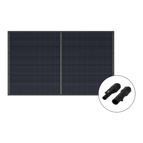
STIEBEL ELTRON TEGREON 235 P Instruction Manual

`V.eC.CZ`<<`.HC
HTV`.HCC.CZ`<<`.HC
sT<H.``.HC`.CZ`<<`.HC
V.8%C.CZ`<<`.
ZV.x.H.CZ`<<x.HC
:t``M8ZCCeZ
TVHpHx.CZ`<
HZAe&..CZ`<8
ixB<``ZZ`<T0`Z
TVp x:.C\`< .
T+H`HpH<`.:éBHe<T+H`HpH<`.BHe<BHe<T+H`HpH<`2Ue%H`HpH<`2Z+
BHe<BHe<H%H`HpH<`.HeV.C:HZ+:MBHee<.%H`HpH<`.:+HBHe<e
BHeA%H`HqH<`.xCtCT<BBHe<%H`HpH<`.:uBHe<
á `&VHCŝŗÑT
á `&VHCŝÔƃT
á `&VHCŝÔÑT

ŝ`&VHC qqqĪZ`.<é<`VHCĪHB
.C+<``V.
<<&B.C+.Cq.Z
BETRIEB
1. Allgemeine Hinweise ________________________________________2
1.1 Sicherheitshinweise_____________________________________________ 2
1.2 Andere Markierungen in dieser Dokumentation __________ 3
1.3 Maßeinheiten_____________________________________________________ 3
2. Sicherheit _____________________________________________________3
2.1 Allgemeine Sicherheitshinweise______________________________ 3
2.2 Bestimmungsgemäße Verwendung _________________________ 3
2.3 Vorschriften, Normen und Bestimmungen_________________ 3
2.4 Prüfzeichen _______________________________________________________ 3
2.5 CE-Kennzeichnung_______________________________________________ 3
INSTALLATION
3. Sicherheit _____________________________________________________4
4. Gerätebeschreibung _________________________________________4
4.1 Notwendiges Zubehör __________________________________________ 4
5. Vorbereitungen_______________________________________________4
5.1 Montageort _______________________________________________________ 4
5.2 Transport __________________________________________________________ 4
6. Montage_______________________________________________________4
6.1 Modul an das Gestell schrauben _____________________________ 4
6.2 Modul an das Gestell klemmen_______________________________ 4
6.3 Elektrischer Anschluss__________________________________________ 5
7. Wartung_______________________________________________________6
8. Demontage____________________________________________________6
9. Technische Daten_____________________________________________7
9.1 Maße _______________________________________________________________ 7
9.2 Datentabelle ______________________________________________________ 8
KUNDENDIENST UND GARANTIE
UMWELT UND RECYCLING
`V.
1. Allgemeine Hinweise
Das Kapitel „Betrieb“ richtet sich an den Anlagenbetreiber und
den Fachhandwerker.
Das Kapitel „Installation“ richtet sich an den Fachhandwerker.
Hinweis
Lesen Sie diese Anleitung vor dem Gebrauch sorgfältig
durch und bewahren Sie sie auf.
Geben Sie die Anleitung ggf. an einen nachfolgenden
Betreiber weiter.
1.1 Sicherheitshinweise
1.1.1 Aufbau von Sicherheitshinweisen
SIGNALWORT Art der Gefahr
Hier stehen mögliche Folgen bei Nichtbeachtung des
Sicherheitshinweises.
fHier stehen Maßnahmen zur Abwehr der Gefahr.
1.1.2 Symbole, Art der Gefahr
ZźăĒù ļŒ®¼ļ&¼Ï|äļ
!
Verletzung
Stromschlag
Brand
1.1.3 Signalwort
Z.&C<qHV` ¼®¼şŒşĉÖ
GEFAHR Hinweise, deren Nichtbeachtung schwere Verletzungen
oder Tod zur Folge haben.

`V.
Z.+V+.`
DEUTSCH
qqqĪZ`.<é<`VHCĪHB `&VHCŗ
1.2 Andere Markierungen in dieser Dokumentation
Hinweis
Hinweise werden durch horizontale Linien ober- und
unterhalb des Textes begrenzt. Allgemeine Hinweise
sind mit dem nebenstehenden Symbol gekennzeichnet.
fLesen Sie die Hinweistexte sorgfältig durch.
ZźăĒù
Geräte- und Umweltschäden
Geräteentsorgung
fDieses Symbol zeigt Ihnen, dass Sie etwas tun müssen.
Die erforderlichen Handlungen werden Schritt für Schritt
beschrieben.
1.3 Maßeinheiten
Hinweis
Wenn nicht anders angegeben, sind alle Maße in Milli-
meter.
2. Sicherheit
2.1 Allgemeine Sicherheitshinweise
Wir gewährleisten eine einwandfreie Funktion und Betriebssicher-
heit nur, wenn das für das Photovoltaik-Modul bestimmte Original-
Zubehör und die originalen Ersatzteile verwendet werden.
fBeachten Sie folgende Punkte:
- Modul nicht in der Nähe von leicht entzündlichen Gasen oder
Dämpfen einsetzen, da Funken entstehen können.
- Kein Sonnenlicht künstlich auf das Modul konzentrieren.
- Keine Lacke, Farben oder Kleber am Modul anbringen.
- Modul nicht auseinandernehmen und keine Teile entfernen.
- Statik des Einsatzorts berücksichtigen.
- Nur unter trockenen Bedingungen arbeiten.
- Module gegen Abrutschen und Umfallen sichern.
- Module nicht fallen lassen.
- Module weder an der Schalterdose noch an den Anschluss-
leitungen halten.
- Module zum Anheben immer gleichzeitig an zwei gegen-
überliegenden Punkten des Rahmens anfassen. Module nie-
mals ausschließlich an einem Rahmenteil tragen.
- Keine Gegenstände auf das Modul fallen lassen.
- Nicht auf das Modul treten.
- Nur unbeschädigte Module verwenden.
- Sicherstellen, dass keine anderen Anlagenkomponenten die
Module mechanisch oder elektrisch beeinträchtigen.
- Keine Löcher in den Modulrahmen oder in die Glasoberfläche
bohren und keine Schweißarbeiten an oder in unmittelbarer
Nähe der Module ausführen.
!GEFAHR Verletzung
Für den gesamten Montageablauf ist die Anwesenheit
einer zweiten Person vorgeschrieben, die bei einem evtl.
Unfall Hilfe leisten kann.
2.2 Bestimmungsgemäße Verwendung
Das Modul ist für den Einsatz in Photovoltaik-Anlagen konzipiert.
Eine andere oder darüber hinausgehende Benutzung gilt als nicht
bestimmungsgemäß. Zum bestimmungsgemäßen Gebrauch ge-
hört auch das Beachten dieser Anleitung sowie der Anleitungen
für eingesetztes Zubehör.
Wir haften nicht für Schäden, die aus Nichtbeachtung dieser An-
leitung, insbesondere der Sicherheitshinweise, sowie aus miss-
bräuchlicher Verwendung des Photovoltaik-Moduls entstehen.
2.3 Vorschriften, Normen und Bestimmungen
Hinweis
Beachten Sie alle nationalen und regionalen Vorschriften
und Bestimmungen.
Das Modul erfüllt folgende Normen:
- IEC/EN 61215 Edition 2
-IEC/EN61730
2.4 Prüfzeichen
Siehe Typenschild am Modul.
2.5 CE-Kennzeichnung
Die CE-Kennzeichnung belegt, dass das Gerät alle grundlegenden
Anforderungen erfüllt:
- Richtlinie über die elektromagnetische Verträglichkeit
- Niederspannungsrichtlinie

Ô`&VHC qqqĪZ`.<é<`VHCĪHB
.CZ`<<`.HC
Z.+V+.`
.CZ`<<`.HC
3. Sicherheit
Die Installation, Inbetriebnahme sowie Wartung und Reparatur
des Moduls darf nur von einem Fachhandwerker durchgeführt
werden.
4. Gerätebeschreibung
4.1 Notwendiges Zubehör
Welches Zubehör zu Ihrem Modul passt, erfahren Sie von Ihrem
Photovoltaikfachhändler. Für die Inbetriebnahme des Moduls be-
nötigen Sie folgendes Zubehör.
-Gestell
- Wechselrichter
- Einspeisezähler
- Gleichstromfreischalter
5. Vorbereitungen
5.1 Montageort
GEFAHR Brand
Installieren Sie das Modul nicht in der Nähe von leicht
entzündlichen Gasen oder Dämpfen, Funkenbildung ist
möglich.
Wählen Sie einen Aufstellort mit maximalem Sonnenlicht zu allen
Jahreszeiten. Vermeiden Sie Bereiche mit Schattenwurf.
Richten Sie in nördlichen Breiten die Anlage nach Süden aus. Be-
stimmen Sie den optimalen Einstellwinkel in Abhängigkeit vom
Breitengrad des Aufstellorts. Erfragen Sie diese Informationen bei
Ihrem Photovoltaikfachhändler.
5.2 Transport
Geräte- und Umweltschäden
Die Module niemals ungesichert transportieren oder
stehen lassen. Andernfalls können Beschädigungen wie
z. B. Glasbruch entstehen.
6. Montage
Je nach Gestellausführung können Sie die Module festgeschrauben
oder festgeklemmen. Das Montagegestell muss aus Belastbarem,
korrosions- und witterungsbeständigem Material bestehen.
6.1 Modul an das Gestell schrauben
26_43_01_0004
fModul auf das Gestell legen.
fVier Edelstahlschrauben (M8) durch die Bohrungen im Rah-
men stecken (siehe „Technische Daten / Maße“).
fSchrauben mit jeweils 2 Edelstahl-Unterlegscheiben, Edel-
stahlfederring oder Zahnscheibe sowie Edelstahlmutter (M8)
am Gestell befestigen.
6.2 Modul an das Gestell klemmen
Eine Klemmung der Module ist an den langen und kurzen Rah-
menseiten im zugelassenen Klemmbereich (siehe „Technische
Daten / Maße“) erlaubt.
Montieren Sie bei der Klemmmontage, zur Sicherheit, eine Ab-
rutschsicherung mittels Verschraubung in der untersten Modul-
reihe.
Hinweis
fBeachten Sie hierzu auch die Installationsanleitung
des Gestellsystems.
Die Klemmstücke dürfen den Modulrahmen zur Glasseite nicht
überragen.
26_43_01_0010
1
2
1 Modulrahmen
2 Klemmstück
fModul auf Gestell legen.
fModul mit Klemmstück festklemmen.

DEUTSCH
qqqĪZ`.<é<`VHCĪHB `&VHCÑ
.CZ`<<`.HC
BHC`&
6.3 Elektrischer Anschluss
Alle relevanten elektrischen Werte sind im Kapitel „Technische
Daten / Datentabelle“ angegeben.
Das Modul kann unter üblichen Betriebsbedingungen die auf dem
Typenschild angegebenen Werte überschreiten. Multiplitzieren Sie
zur Bestimmung der Spannungsbemessungswerte von Bauteilen,
Strombemessungswerte von Kabeln und Größen von Sicherungen
die angegebenen Werte für Kurzschlussstrom und Leerlaufspan-
nung mit einem Faktor 1,25.
Die Solar-Module erfüllen die Anforderungen der Anwendungs-
klasse A. Sie können in frei zugänglichen Systemen mit mehr als
50V Gleichspannung (DC) oder 240W Leistung einsetzen.
GEFAHR Stromschlag
Trennen Sie keine Verbindungen unter Last.
Sorgen Sie für ausreichenden Schutz gegen Kontakt mit
spannungsführenden Teilen.
fVerwenden Sie ausschließlich isoliertes Werkzeug.
6.3.1 Parallel- und Reihenschaltung
Hinweis
Die Anforderungen hinsichtlich Erdung müssen vor
Beginn der Arbeiten gemäß den geltenden Vorschriften
und Standards geprüft werden.
fBeachten Sie die Position der Erdungsborung im Ka-
pitel „Technische Daten / Maße“.
Module derselben Bauart können Sie parallel oder in Serie schal-
ten.
Geräte- und Umweltschäden
Um Beschädigungen zu vermeiden:
fVerwenden Sie bei Reihen- und Parallelschaltung
nur Module derselben Bauart und Leistung.
fSie müssen bei der Auslegung der Verschaltung alle
elektrischen Grenzwerte der an das System ange-
schlossenen Komponenten einhalten. Dies bezieht
sich in erster Linie auf die Anzahl der in Reihe bzw.
parallel geschalteten Module.
fStellen Sie sicher, dass die Polung korrekt ist.
Die Schalterdose befindet sich auf der Rückseite des Moduls:
26_43_01_0002
123
4
1 Schalterdose
2 Stecker
3 Anschlussleitungen
4 Buchse
fNehmen Sie den Stecker und die Buchse aus der Halterung.
fVerbinden Sie den Stecker des Moduls mit der Buchse des
nächsten Moduls.
26_43_01_0089
fVerriegeln Sie den Stecker mit der Buchse um 90° bis zum
Anschlag.
fSchließen Sie den Stecker oder die Buchse des ersten und
des letzten Moduls innerhalb des elektrischen Strangs an die
Strangleitung zum Wechselrichter an.
6.3.2 Erdung
Eine Erdungsleitung können Sie an den Bohrungen im Rahmen
befestigen (siehe Kapitel „Technische Daten / Maße“).

ō`&VHC qqqĪZ`.<é<`VHCĪHB
.CZ`<<`.HC
qV`eC&
7. Wartung
Die Module sind wartungsarm. Wir empfehlen eine jährliche Sicht-
prüfung.
fKontrollieren Sie dabei auch die mechanischen Verbindungen
und die elektrischen Anschlüsse auf Beschädigungen.
Verschmutzungen der Module verringern die Leistung und den
Ertrag. Wenn die Module in einem Neigungswinkel von mehr als
15° montiert sind, ist eine Reinigung durch Regen in der Regel
ausreichend.
Geräte- und Umweltschäden
Um Beschädigungen durch Verkratzen oder hohe Tem-
peraturunterschiede zu vermeiden:
fVerwenden Sie zur Reinigung ausschließlich Neut-
ral-Flüssigreiniger.
fVerwenden Sie keine Reinigungsmittel mit Scheuer-
oder Schleifwirkung.
fVerwenden Sie nur Wasser, das der Temperatur der
Moduloberfläche angepasst ist.
fWischen Sie die Moduloberfläche mit Wasser und
einem weichen Lappen ab.
8. Demontage
GEFAHR Stromschlag
Trennen Sie keine Verbindungen unter Last.
Sorgen Sie für ausreichenden Schutz gegen Kontakt mit
spannungsführenden Teilen.
fVerwenden Sie ausschließlich isoliertes Werkzeug.
Um die Photovoltaik-Anlage lastfrei zu machen:
fTrennen Sie den Wechselrichter AC-seitig vom
Versorgungsnetz.
fTrennen Sie die Photovoltaik-Anlage an der DC-seitigen
Trennstelle vom Wechselrichter.
fStellen Sie sicher, dass das System ohne elektrische Span-
nung ist.
fDemontieren Sie die Photovoltaik-Anlage analog zur Monta-
ge. Beachten Sie die Sicherheitshinweise.

DEUTSCH
qqqĪZ`.<é<`VHCĪHB `&VHCŌ
.CZ`<<`.HC
`+C.Z+`C
9. Technische Daten
9.1 Maße
[
[
[
[
L
D0000018257
i30 Klemmbereich

Ä`&VHC qqqĪZ`.<é<`VHCĪHB
.CZ`<<`.HC
`+C.Z+`C
9.2 Datentabelle
`&VHCŝŗÑT `&VHCŝÔƃT `&VHCŝÔÑT
273275 273276 273277
Elektrische Daten
Systemspannung max. V1000 1000 1000
Rückstrombelastbarkeit (IR) A 20 20 20
Wirkungsgrad bei verminderter Einstrahlung (200 W/m² anstelle
von 1000 W/m² nach EN 60904-1)
97% vom STC-Wirkungs-
grad
97% vom STC-Wirkungs-
grad
97% vom STC-Wirkungs-
grad
Elektrische Daten bei STC
Nennleistung STC (PN) W 235 240 245
Modulwirkungsgrad STC %14,44 14,74 15,05
Nennspannung STC (UMPP) V 29,43 29,56 29,81
Leistungstoleranz min. STC % 0 0 0
Leistungstoleranz max. STC %2,5 2,5 2,5
Leerlaufspannung STC (UOC) V 36,47 36,64 36,89
Nennstrom STC (IMPP) A 8,1 8,17 8,29
Kurzschlussstrom STC (ISC) A 8,53 8,62 8,71
Temperaturkoeffizient absolut (ISC)mA/°C 4,065 4,106 4,148
Temperaturkoeffizient absolut (UOC)V/°C -0,111 -0,111 -0,112
Temperaturkoeffizient prozentual (ISC)%/°C 0,059 0,059 0,059
Temperaturkoeffizient prozentual (PMPP)%/°C -0,44 -0,44 -0,44
Temperaturkoeffizient prozentual (UOC)%/°C -0,33 -0,33 -0,33
Elektrische Daten bei 800 W/m², NOCT, AM 1,5
Leistung bei 800 W/m2, NOCT, AM 1,5 (PMPP) W 174,4 176,8 180,8
Spannung bei 800 W/m2, NOCT, AM 1,5 (UMPP) V 27,2 27,3 27,6
Leerlaufspannung bei 800 W/m2, NOCT, AM 1,5 (UOC) V 33,5 33,7 33,9
Strom bei 800 W/m2, NOCT, AM 1,5 (IMPP) A 6,4 6,47 6,54
Kurzschlussstrom bei 800 W/m2, NOCT, AM 1,5 (ISC) A 6,89 6,96 7,03
NOCT °C 44± 2 44± 2 44± 2
Dimensionen
Höhe mm 1651 1651 1651
Breite mm 986 986 986
Tiefe mm 46 46 46
Kantenlänge Zelle mm 156 156 156
Gewichte
Gewicht kg 19,6 19,6 19,6
Ausführungen
Anzahl Zellen 60 60 60
Solarzellentyp polykristallin polykristallin polykristallin
Zelltyp
Rahmenmaterial Aluminium Aluminium Aluminium
Frontabdeckung mikrostrukturiertes Solar-
glas
mikrostrukturiertes Solar-
glas
mikrostrukturiertes Solar-
glas
Anschlüsse
Modulanschluss Hersteller Huber + Suhner Huber + Suhner Huber + Suhner
Modulanschluss Kabellänge mm 1000 1000 1000
Modulanschluss Kabelquerschnitt mm² 4 4 4
Modulanschluss Verbindung Steckverbinder mit integ-
rierter Drehverriegelung
Steckverbinder mit integ-
rierter Drehverriegelung
Steckverbinder mit integ-
rierter Drehverriegelung
Die elektrischen Daten bei STC (Standard-Testbedingungen): Strahlungsleistung von 1.000 W/
m² bei einer spektralen Dichte von AM 1,5 und Zelltemperatur von 25°C.

DEUTSCH
qqqĪZ`.<é<`VHCĪHB `&VHCĎ
:eCC.CZ`eC&VC`.
! "
'<99@226;:.926;2'@M>A;4.;26;2:A;?2>2>$><1A8@2.A3@>2@2;
?@25@5;2;1.?*2>@>62/?A;@2>;25:2;/2612:'62162?2?!<1A9
2>C<>/2;5./2;:6@&.@A;1(.@FA>'26@2
"#' "$"#
(
"# ' #"# !"#!
+6>?@2992;5M05?@2;?=>N052.;162%A.96@L@A;?2>2>$><1A8@2
62?2C2>12;A;@2>2.05@A;45M05?@2>%A.96@L@?.;3<>12>A;42;
4232>@64@+6>4.>.;@62>2;12:2@>26/2>12>$5<@<B<[email protected]!<1A92
6:<942;12;IA;12H1.52>3N>162.A2>B<;O.5>2;1.??
162$5<@<B<9@.68!<1A92(&#"O,,$3>26B<;$><1A8@<12>
2>?@299A;4?32592>;?6;1
!"#! "
+6>4.>.;@62>2;12:A;12;3N>!<1A92:6@26;2> 26?@A;4?
@<92>.;FB<;O1.??162$5<@<B<[email protected]!<1A923N>26;2
.A2>B<;O.5>2;;605@C2;642>.9?O12>.A312: ./29
.;4242/2;2;"<:6;.9926?@A;4?<C623N>162.A2>B<;O.5>2;
;605@C2;642>.9?O12>.A312: ./29.;4242/2;2;"<:6
;.9926?@A;42>/>6;42;62?2 26?@A;4?4.>.;@621208@.A??05962J
9605 26?@A;4?:6;12>A;42;./162.A34>A;1B<;-299124>.1.@6<;
2;@?@252;
26?@A;4?:6;12>A;42;1626;3<942B<;!.@2>6.9<12>*2>.>/26
@A;4?32592>;2;@?@252;C2>12;;605@2>?2@F@
62 26?@A;4?:6;12>A;4:A??1A>0526;2B<;A;?.A@<>6?62>@2
(2?@6;?@.;F6;26;2:2;@?=>2052;1.A@<>6?62>@2;(2?@B2>3.5>2;
A;@2>'@.;1.>1@2?@/216;4A;42;'(32?@42?@299@C<>12;?26;
62<?@2;12> 26?@A;4?N/2>=>N3A;4@>.42;C6>;A>/26*<>96242;
26;2?.>.;@623.992?
#!!#!!#! &# "
62.>.;@62;A:3.??2;826;2226;@>L05@64A;42;12>$5<@<B<9
@.68!<1A921621.1A>052;@?@.;12;?6;11.??
926@A;4B<;26;2:.05/2@>62/:<;@62>@CA>12;
162$5<@<B<[email protected]!<1A92<5;22.05@A;412>.;2>8.;;@2;
&2429;12>(205;68@>.;?=<>@62>@26;42/.A@:<;@62>@42
=>N3@>2=.>62>@42>26;64@42=24@<12>/2@>62/2;CA>12;
162$5<@<B<[email protected]!<1A92;605@2;@?=>2052;112>B2>26;/.>@2;
@205;6?052;'=2F68.@6<;<12>2;@4242;12:B<>42?252;2;
*2>C2;1A;4?FC20842;A@F@CA>12;
162$5<@<B<[email protected]!<1A92B<>A;1CL5>2;112>!<;@.42;605@
?.0542:LJ429.42>@CA>12;
6;4>6332A;1*2>L;12>A;42;.;12;$5<@<B<[email protected]!<1A92;
A;165>2:-A/25M><12>):/.A.>/26@2;<5;2.A?1>N0896052
-A?@6::A;4B<;A;?B<>42;<::2;CA>12;
162$5<@<B<9@.68!<1A92.AJ2>42CM5;96052;):42/A;4?
26;N??2;'.;1?@N>:2K/2>?=.;;A;4!.4;2@32912>;<OL
.A?42?2@F@C.>2;
162$5<@<B<[email protected]!<1A925M52>2>2C.9@FO96@F?059.4
.429?059.42A2>*.;1.96?:A?A;1".@A>8.@.?@><=52;
.A?42?2@F@C.>2;
62.>.;@62;A:3.??2;826;2:6@@29/.>2;'05L12;6;?/2?<;12>2
826;2"2/2;A;1<942?05L12;26;?05962J9605$2>?<;2;<12>
'.05?05L12;2;@4.;42;2>2C6;;/FC2;@4.;42;26;?=26?2
B2>4N@A;4A;1<12><?@2;3N>>?.@F?@><:/2FA4&A3?05L164A;4
.@2;B2>9A?@+2>/2<12>2>?@299A;4?8<?@2;2:26;8<?@2;A;1
*2>9A?@B<;A;12;?<C62<?@2;1621A>052@>62/?A;@2>/>2
05A;4<12>6;-A?.::2;5.;4:6@12>2:<;@.42);@2>?A05A;4
;@?<>4A;4"2A6;?@.99.@6<;<12>12:(>.;?=<>@12?12328@2;
?<C6212?FA96232>;12;$5<@<B<9@.68!<1A9?2;@?@252;
2> 26?@A;4?<>@12>.>.;@62926?@A;42;6?@6:.>.;@623.99B<>./
.;FA3>.42;A;1C6>1B<;'( (&#"/2?@6::@62&N08
?2;1A;412>+.>28.;;;A>;.05B<>52>642>!6@@269A;426;2>
(>.;?=<>@&289.:.@6<;?;A::2>2>3<942;
?9624@826;.>.;@623.99B<>C2;;A;C2?2;@960522592><12>
/C2605A;42;6;12>2?05.332;526@12>$5<@<B<[email protected]!<1A92B<>
96242;1623N>12;+2>@A;112;/2?@6::A;4?42:LJ2;2/>.A05
A;2>52/9605?6;1
(>6@@26;.>.;@623.9926;3N5>2;C6>;.052642;2>;@?05261A;4
2;@C212>26;23.05:L;;6?052&2=.>.@A>12>/2@><332;2;(2692
1A>05<12>2>?2@F2;162+.>21A>05;2A2<12>C2>8?N/2>5<9@2
(2692212?2>?2@F@2!<1A9C6>1A;?2>642;@A:'<C26@162/2
@>2332;12;!<1A92;605@:25>52>42?@299@C2>12;?6;1C6>/2
>205@64@26;2;.;12>2;492605C2>@642;!<1A9@E=FA96232>;
62>/>6;4A;4B<;.>.;@62926?@A;42;9M?@C212>12;246;;
;2A2>.>.;@629.A3F26@2;.A?;<05C6>1162.>.;@62F26@1.1A>05
B2>9L;42>@
&#"# "
62?2.>.;@62/216;4A;42;429@2;.A??05962J96053N>6;;2>5.9/
2A@?059.;1?A;1 AD2:/A>42>C<>/2;2$><1A8@2N>6;1.?
?<;?@642A?9.;1N/2>3N5>@22>L@2429@2;443.;12>2.>.;@62
/216;4A;42;
N>.AJ2>5.9/2A@?059.;1?2>C<>/2;22>L@2429@2;;605@162
.>.;@62/216;4A;42;A;?2>2>12A@?052;2?299?05.3@2;*629:25>
8.;;6; L;12>;6;12;2;26;2(<05@2>42?299?05.3@2D6?@62>@26;2
.>.;@62;A>B<;162?2>(<05@2>42?299?05.3@2>@269@C2>12;6;2
?<9052.>.;@626?@;A>1.;;2>@269@C2;;162(<05@2>42?299?05.3@
2642;2.>.;@62/216;4A;42;52>.A?4242/2;5.@.>N/2>56;.A?
C6>1826;2.>.;@622>@269@
N>2>L@21626; L;12>;2>C<>/2;C2>12;6;12;2;826;2(<05
@2>42?299?05.3@2D6?@62>@2>@2692;C6>826;2.>.;@62@C.642B<:
:=<>@2A>FA42?6052>@2.>.;@62;/926/2;562>B<;A;/2>N5>@
62.>.;@62469@;A>C2;;162?22162;A;4?A;1;[email protected].@6<;?
.;926@A;4/2.05@2@CA>12
62.A3423N5>@2;.>.;@623>6?@2;/246;;2;72C269?:6@12:(.4
12?.A3?.@A:12>&205;A;41A>0512;>?@/2@>26/2>
"$ #!!"%#
?@12>A;12*2>/>.A052>5.@2>A;?<332;?605@960522592>12>
$5<@<B<9@.68!<1A926;;2>5.9/B<;O!<;.@2;;.05>5.9@?05>63@
9605.;FAF2642;.;12>2;3.99?6?@16229@2;1:.05A;412>.>.;
@62.;?=>N052.A?42?059<??2;
?@12>A;12);@2>;25:2>?2@F2;.>.;@62.;?=>N05212?A;12;
B<>.A?1.??2>?26;2;;.05G42?05A912@2;);@2>?A
05A;4?A;1&N42</96242;526@2;<>1;A;4?42:LJ;.05428<:
:2;6?@

Ĝƃ`&VHC qqqĪZ`.<é<`VHCĪHB
:eCC.CZ`eC&VC`.
/,,3&.%*&)/3/5/,3"*+/%4,&&*.&.4.3&1%*&2&"1".3*&.'",
,&.%&.&),&1"4'6&*2&.6&.%&.*&2*$)#*33&4.5&19>(,*$)".
%"2&131*.3&1.&)-&.#&*%&-*&%*&2&2/%4,&16/1#&.
)"#&.*33&)",3&.*&'>1%&.&,&'/.".14'23&32'/,(&.%&.'/1
-"3*/.&.#&1&*3
)1&."-&.%1&22&/23,&*39"),4.%&*.&&,&'/..4--&1
4.3&1%&1*&94&11&*$)&.2*.%
%*&/%&,,#&9&*$).4.(4.%%*&&1*&..4--&1%&2)/3/5/,
3"*+/%4,2#&*%&2+=..&.*&"-/%4,"#,&2&.
&*.&."4'#&,&(-*3"34-4.%.2$)1*'3%&2&1+<4'&12
%"2.23",,"3*/.2%"34-
134.%%1&22&%&1.23",,"3*/.
&*.&5/,,23<.%*(&4*234.(%&1#&/#"$)3&3&.&),&1&,
%4.(&."-&1<3#96%&1.,"(&4.%6&*3&1&1.'/1-"3*/
.&.%*&941.",82&%&2&),&12#&*31"(&.+=..&.
%*&1=:&%&1&2"-3".,"(&*.+ 0
4'.'1"(&2*.%4.2'/,(&.%&.3&1,"(&.4.%.'/1-"3*/.&.941
&1'>(4.(9423&,,&.
/3/2%&1#&2$)<%*(3&./%4,&
%"2$)",3#*,%%&1.,"(&
(('24'9&*$).4.(&."42%&1"3&.&1'"224.(
*&*3"1#&*3&16&1%&.*&>#&1%*&6&*3&1&/1(&)&.26&*2&
*.'/1-*&1&.4.%).&.)1&*.%*5*%4&,,&&+,"-"3*/.2.4--&1
-*33&*,&.*33&(&#&.*&%*&2&#&*-.'/1-"3*/.2"423"42$)*-
")-&.%&1#6*$+,4.(%&1&+,"-"3*/.23&32".
/6&*3*&5/.%&-*3"1#&*3&1"4'(&'/1%&136&1%&.*)-*-&
201<$).<)&1#&23*--3&"4'4.3&1,"(&.94942&.%&.2*.%%*&2&
0/23",*2$)/%&10&1"7".&*.&5/.*)-#&."..3&%1&22&94
>#&1-*33&,.&),3%*&&$).4.(/%&1%*&.("#&%&1&1*&..4-
-&1#&23&)3+&*."1".3*&".2014$)
*33&#&"$)3&.*&%"22)/3/5/,3"*+/%4,&6&,$)&/).&5/1
)&1(&)&.%&3&,&'/.*2$)&&,%4.(2/6*&/).&1".20/13&+,"
-"3*/.2.4--&1&*.(&)&..*$)3".(&./--&.6&1%&.+=..&.
&1.2014$)%&24.%&."42%*&2&."1".3*&.#&2$)1<.+32*$)
"4'%*&"4'(&'>)13&."1".3*&,&*234.(&.
*1)"'3&..*$)3'>1&19=(&14.(&./%&1*$)3&1#1*.(4.(5/.
"4'(&'>)13&."1".3*&,&*234.(&.2/6&*3%*&2"4')=)&1&&6",3
1*&(+1*&(2<).,*$)&!423<.%&.14)&.31&*+0*%&-*&.
&4&1;#&12$)6&--4.(/%&1".%&1&5&1(,&*$)#"1&-23<.%&
%*&"4:&1)",#%&2&1".36/134.(2#&1&*$)25/.4.2,*&(&.94
1>$+94'>)1&.*23
*&2&"1".3*&4.3&1,*&(3%&-&$)3%&14.%&21&04#,*+&432$)
,".%4.3&1422$),422%&2/,,*2*/.21&$)322/6*&%&2"4'
1&$)32
/,9-*.%&.3".%4.*
*33&)&,'&.*&4.2&1&-6&,3942$)>39&..32/1(&.*&%*&
&10"$+4.((&-<:."3*/.",&1/12$)1*'3&.

ENGLISH
qqqĪZ`.<é<`VHCĪHB `&VHCĜĜ
HC`C`ZHTV`.HC
&CV<.C%HVB`.HC
OPERATION
1. General information _______________________________________ 11
1.1 Safety instructions______________________________________________ 11
1.2 Other symbols in this documentation ______________________ 12
1.3 Units of measurement _________________________________________ 12
2. Safety________________________________________________________ 12
2.1 General safety instructions ___________________________________ 12
2.2 Intended use_____________________________________________________12
2.3 Instructions, standards and regulations ___________________ 12
2.4 Test symbols _____________________________________________________12
2.5 CE designation __________________________________________________ 12
INSTALLATION
3. Safety________________________________________________________ 13
4. Equipment description ____________________________________ 13
4.1 Required accessories __________________________________________ 13
5. Preparations________________________________________________ 13
5.1 Installation location ____________________________________________ 13
5.2 Handling__________________________________________________________ 13
6. Mounting____________________________________________________ 13
6.1 Securing the module to the frame with screws __________ 13
6.2 Clamping the module to the frame__________________________ 13
6.3 Power supply ____________________________________________________ 14
7. Maintenance ________________________________________________ 14
8. Dismantling _________________________________________________ 15
9. Specification ________________________________________________ 15
9.1 Dimensions_______________________________________________________ 15
9.2 Data table ________________________________________________________ 16
CUSTOMER SERVICE AND WARRANTY
ENVIRONMENT AND RECYCLING
HTV`.HC
1. General information
The chapter entitled "Operation" is intended for the operator and
the heating contractor.
The chapter "Installation" is intended for heating contractors.
Note
Read these instructions carefully before using the appli-
ance and retain them for future reference.
Pass on the instructions to a new user if required.
1.1 Safety instructions
1.1.1 Structure of safety instructions
KEYWORD Type of risk
Here, possible consequences are listed that may result
from failure to observe the safety instructions.
fSteps to prevent the risk are listed.
1.1.2 Symbols, type of risk
ZźăĒù `źĤ¼ĒÏļêń÷
!
Injury
Electrocution
Fire
1.1.3 Keyword
:tqHV B¼|ĉêĉÖ
DANGER Failure to observe this information will result in serious
injury or death.

HTV`.HC
Z%`t
Ĝŝ`&VHC qqqĪZ`.<é<`VHCĪHB
1.2 Other symbols in this documentation
Note
Notes are bordered by horizontal lines above and below
the text. General information is identified by the adjacent
symbol.
fRead these texts carefully.
ZźăĒù
Damage to the appliance and environment
Appliance disposal
fThis symbol indicates that you have to do something. The ac-
tion you need to take is described step by step.
1.3 Units of measurement
Note
All measurements are given in mm unless stated oth-
erwise.
2. Safety
2.1 General safety instructions
We guarantee trouble-free operation and operational reliability
only if the original accessories and spare parts intended for the
photovoltaic module are used.
fPlease observe the following:
- Never use the module near easily combustible gases or va-
pours, as sparks may be produced.
- Never concentrate any sunlight artificially on the module.
- Never apply varnishes, paints or adhesives to the module.
- Never dismantle the module or remove any parts.
- Take into account the statics of the location of use.
- Only work under dry conditions.
- Secure modules to prevent them slipping or falling over.
- Never allow module to fall.
- Never hold modules by their switch panel or by the connect-
ing cables.
- Always lift modules by holding two opposite points of the
frame simultaneously. Never carry modules just by one part
of the frame.
- Never allow any objects to fall on the module.
- Never stand on the module.
- Only use undamaged modules.
- Ensure that no other system components are impairing the
modules mechanically or electrically.
- Never drill holes in the module frame or the glass surface
and never carry out any welding work on or directly near to
the modules.
!DANGER Injury
A second person who can provide help in the event of a
possible accident is required to be present for the entire
installation process.
2.2 Intended use
The module is designed for use in photovoltaic systems.
Any other use beyond that described shall be deemed inappropri-
ate. Observation of these instructions and of instructions for any
accessories used is also part of the correct use of this appliance.
We assume no liability for damage arising from failure to observe
these instructions, in particular the safety instructions, as well as
from misuse of the photovoltaic module.
2.3 Instructions, standards and regulations
Note
Observe all applicable national and regional regulations
and instructions.
The module fulfils the following standards:
- IEC/EN 61215 Edition 2
- IEC/EN 61730
2.4 Test symbols
See type plate on the module.
2.5 CE designation
The CE designation shows that the appliance meets all essential
requirements according to the:
- Electromagnetic Compatibility Directive
- Low Voltage Directive

ENGLISH
qqqĪZ`.<é<`VHCĪHB `&VHCĜŗ
.CZ`<<`.HC
Z%`t
.CZ`<<`.HC
3. Safety
Only qualified contractors should carry out installation, commis-
sioning, maintenance and repair of the module.
4. Equipment description
4.1 Required accessories
Your photovoltaics dealer can advise you on which accessories are
suitable for your module. You require the following accessories
for commissioning the module.
- Frame
- Inverter
- Supply meter
- DC disconnect switch
5. Preparations
5.1 Installation location
DANGER Fire
Never install the module near flammable gases or va-
pours; the module may generate sparks.
Choose an installation location with maximum sunlight all year
round. Avoid areas in shadow.
In northerly climes, position the system so that it faces south. De-
termine the optimum adjustment angle depending on the latitude
of the installation location. Ask your photovoltaics dealer for this
information.
5.2 Handling
Damage to the appliance and environment
Never transport the modules without securing them or
leave them unsecured. Otherwise damage such as glass
breakage may occur.
6. Mounting
Depending on the frame configuration, the modules can be se-
cured with screws or clamped. The installation frame must be
made of a strong, corrosion and weather-resistant material.
6.1 Securing the module to the frame with screws
26_43_01_0004
fLay the module on the frame.
fInsert four stainless steel screws (M8) through the holes in
the frame (see "Specification"/"Dimensions").
fSecure screws to frame, in each case using 2 stainless steel
washers, a stainless steel spring washer or serrated washer
and stainless steel nut (M8).
6.2 Clamping the module to the frame
The modules may only be clamped to the long and short frame sides
in the permitted clamping area (see "Specification"/"Dimensions").
When using the clamping method, for safety reasons apply an
anti-slip facility that is secured with screws to the lowest row of
modules.
Note
fAlso observe the installation instructions for the
frame system in this connection.
The clamping brackets must not protrude from the module frame
to the glass side.
26_43_01_0010
1
2
1 Module frame
2 Clamping bracket
fLay the module on the frame.
fClamp the module with the clamping bracket.

ĜÔ`&VHC qqqĪZ`.<é<`VHCĪHB
.CZ`<<`.HC
B.C`CC
6.3 Power supply
All relevant electrical values are given in chapter "Specification/
Data table".
The module may, under normal operating conditions, exceed the
values specified on the type plate. To determine the rated voltage
values of components, multiply rated current values of cables and
fuse sizes, the specified values for the short circuit current and
off-load voltage by a factor of 1.25.
The PV modules meet the requirements of application category
A. They can be used in freely accessible systems with more than
50V DC or 240 W output.
DANGER Electrocution
Never disconnect any connections under load.
Make sure there is sufficient protection against contact
with live components.
fOnly use insulated tools.
6.3.1 Connection in parallel and in series
Note
The requirements with regard to earthing must be
checked before commencing work in accordance with
the applicable regulations and standards.
fObserve the position of the earth hole in the chapter
"Specification"/"Dimensions".
Modules of the same type may be connected in parallel or in
series.
Damage to the appliance and environment
To avoid damage:
fOnly use modules of the same type and output for
series and parallel circuits.
fWhen designing the wiring, you must observe all
electrical limit values for components connected to
the system. This applies primarily to the number of
modules connected in series or in parallel.
fEnsure that the polarity is correct.
The switch panel is located at the back of the module:
26_43_01_0002
123
4
1 Switch panel
2 Plug
3 Connecting cables
4 Socket
fRemove the plug and socket from the retainer.
fConnect the plug of this module with the socket of the next
module.
26_43_01_0089
fLock the plug inside the socket by turning it 90° as far as it
will go.
fConnect the plug or socket of the first and last module in the
electrical line to the inverter cable.
6.3.2 Earth
You can secure an earth cable via the holes in the frame (see
chapter "Specification"/"Dimensions").
7. Maintenance
The modules are low-maintenance. We recommend an annual
visual inspection.
fAlso check the mechanical and electrical connections for
damage.
Dirt on the modules reduces the output and yield. If the modules
are installed at an angle of inclination of more than 15°, rain is
generally sufficient to clean them.
Damage to the appliance and environment
To avoid damage caused by scratching or high tempera-
ture differentials:
fUse exclusively liquid neutral cleaning agents to
clean modules.
fNever use scouring or abrasive cleaning agents.
fOnly use water matched to the temperature of the
module surface.
fWipe the module surface with water and a soft
cloth.

ENGLISH
qqqĪZ`.<é<`VHCĪHB `&VHCĜÑ
.CZ`<<`.HC
.ZBC`<.C&
8. Dismantling
DANGER Electrocution
Never disconnect any connections under load.
Make sure there is sufficient protection against contact
with live components.
fOnly use insulated tools.
To make the photovoltaic system load-free:
fIsolate the inverter from the mains on the AC side.
fDisconnect the photovoltaic system from the inverter at the
disconnect point on the DC side.
fEnsure that there is no electrical voltage in the system.
fDismantle the photovoltaic system in reverse order to its in-
stallation. Observe all safety instructions.
9. Specification
9.1 Dimensions
[
[
[
[
L
D0000018257
i30 clamping areas

Ĝō`&VHC qqqĪZ`.<é<`VHCĪHB
.CZ`<<`.HC
ZT.%.`.HC
9.2 Data table
`&VHCŝŗÑT `&VHCŝÔƃT `&VHCŝÔÑT
273275 273276 273277
Electrical details
Max. system voltage STC V1000 1000 1000
Reverse current capacity STC (IR) A 20 20 20
Efficiency at reduced insolation (200 W/m² instead of 1000 W/m² to EN
60904-1)
97% of STC efficiency 97% of STC efficiency 97% of STC efficiency
Electrical data at STC
Rated output STC (PN) W 235 240 245
Module efficiency STC %14,44 14,74 15,05
Rated voltage STC (UMPP) V 29,43 29,56 29,81
Min. output tolerance STC % 0 0 0
Max. output tolerance STC %2,5 2,5 2,5
Open circuit voltage STC (UOC) V 36,47 36,64 36,89
Rated current STC (IMPP) A 8,1 8,17 8,29
Short circuit current approx. STC (ISC) A 8,53 8,62 8,71
Temperature coefficient absolute (ISC)mA/°C 4,065 4,106 4,148
Temperature coefficient absolute (UOC)[V/°C] -0,111 -0,111 -0,112
Temperature coefficient as a percentage (ISC)%/°C 0,059 0,059 0,059
Temperature coefficient as a percentage (PMPP)%/°C -0,44 -0,44 -0,44
Temperature coefficient as a percentage (UOC)%/°C -0,33 -0,33 -0,33
Electrical data at 800 W/m², NOCT, AM 1.5
Output at 800 W/m2, NOCT, AM 1.5 (PMPP) W 174,4 176,8 180,8
Voltage at 800 W/m2, NOCT, AM 1.5 (UMPP) V 27,2 27,3 27,6
Idle voltage at 800 W/m2, NOCT, AM 1.5 (UOC) V 33,5 33,7 33,9
Current at 800 W/m2, NOCT, AM 1.5 (IMPP) A 6,4 6,47 6,54
Short circuit current at 800 W/m2, NOCT, AM 1.5 (ISC) A 6,89 6,96 7,03
NOCT °C 44± 2 44± 2 44± 2
Dimensions
Height mm 1651 1651 1651
Width mm 986 986 986
Depth mm 46 46 46
Width of cell mm 156 156 156
Weights
Weight kg 19,6 19,6 19,6
Versions
Number of cells 60 60 60
Type of solar cell Polycrystalline Polycrystalline Polycrystalline
Cell type
Frame material Aluminium Aluminium Aluminium
Front cover Micro-structured solar
glass
Micro-structured solar
glass
Micro-structured solar
glass
Connections
Module connection, manufacturer Huber + Suhner Huber + Suhner Huber + Suhner
Module connection, cable length mm 1000 1000 1000
Module connection, cable cross-section mm² 4 4 4
Type of module connection Plug-in connector with
integral twist lock
Plug-in connector with
integral twist lock
Plug-in connector with
integral twist lock
The electrical data under STC (standard test conditions): Radiation efficiency of 1000 W/m²
with a spectral density of AM 1.5 and cell temperature of 25 °C.

ENGLISH
qqqĪZ`.<é<`VHCĪHB `&VHCĜŌ
&eVC`Cp.VHCBC`CVt<.C&
!
!

ĜÄ`&VHC qqqĪZ`.<é<`VHCĪHB
`<ZB`. VZe`.<.Z`.HC
VBVUeZ&CV<Z
EXPLOITATION
1. Remarques générales _____________________________________ 18
1.1 Consignes de sécurité__________________________________________ 18
1.2 Autres repérages utilisés dans cette documentation____ 19
1.3 Unités de mesure _______________________________________________ 19
2. Sécurité _____________________________________________________ 19
2.1 Consignes de sécurité générales ____________________________ 19
2.2 Utilisation conforme ___________________________________________ 19
2.3 Prescriptions, normes et directives _________________________ 19
2.4 Label de conformité ____________________________________________ 19
2.5 Marquage CE ____________________________________________________ 19
MONTAGE
3. Sécurité _____________________________________________________ 20
4. Description de l‘appareil __________________________________ 20
4.1 Accessoires requis______________________________________________ 20
5. Travaux préparatoires_____________________________________ 20
5.1 Lieu d’implantation_____________________________________________20
5.2 Transport _________________________________________________________20
6. Montage_____________________________________________________ 20
6.1 Vissage du module au châssis _______________________________20
6.2 Bridage du module au châssis_______________________________20
6.3 Raccordement électrique _____________________________________ 21
7. Maintenance ________________________________________________ 21
8. Démontage__________________________________________________ 22
9. Données techniques _______________________________________ 23
9.1 Dimensions_______________________________________________________23
9.2 Tableau de données____________________________________________ 23
SERVICE CLIENTÈLE ET GARANTIE
ENVIRONNEMENT ET RECYCLAGE
sT<H.``.HC
1. Remarques générales
Le chapitre «Exploitation» s’adresse aux exploitants de l’instal-
lation et aux installateurs.
Le chapitre «Installation» s’adresse aux installateurs.
Remarque
Veuillez lire attentivement cette notice avant utilisation
et conservez-la.
Remettez cette notice au nouvel exploitant le cas échéant.
1.1 Consignes de sécurité
1.1.1 Structure des consignes de sécurité
MENTION D‘AVERTISSEMENT Nature du danger
Sont indiqués ici les risques éventuellement encourus
en cas de non-respect de la consigne de sécurité.
fSont indiquées ici les mesures permettant de
pallier au danger.
1.1.2 Symboles, nature du danger
ZźăĒù¼ C|Œşļ¼®ş®|ĉÖ¼ļ
!
Blessure
Électrocution
Incendie
1.1.3 Mention d‘avertissement
BC`.HCZ
ĸpV`.ZZé
BC`
ZêÖĉêÏê|ŒêĒĉ
DANGER Caractérise des remarques dont le non-respect entraîne de
graves lésions, voire la mort.

sT<H.``.HC
ZeV.`
FRANÇAIS
qqqĪZ`.<é<`VHCĪHB `&VHCĜĎ
1.2 Autres repérages utilisés dans cette documen-
tation
Remarque
Les remarques sont délimitées par des lignes horizontales
au-dessus et en dessous du texte. Le symbole ci-contre
caractérise des remarques générales.
fLisez attentivement les textes de remarque.
ZźăĒù¼
Endommagements de l‘appareil et pollution de l‘environ-
nement
Recyclage de l‘appareil
fCe symbole vous indique que vous devez agir. Les actions né-
cessaires sont décrites étape par étape.
1.3 Unités de mesure
Remarque
Sauf indication contraire, toutes les cotes sont indiquées
en millimètres.
2. Sécurité
2.1 Consignes de sécurité générales
Nous ne garantissons un bon fonctionnement en toute sécurité
du module photovoltaïque que si les accessoires et pièces de re-
change d’origine sont employés.
fTenez compte des points suivants:
- ne pas utiliser le module à proximité de gaz facilement in-
flammables car des étincelles peuvent se produire.
- Ne pas concentrer artificiellement les rayons du soleil sur le
module.
- Ne pas appliquer de vernis, peinture ou colle sur le module.
- Ne pas désassembler le module et ne pas en retirer
d‘éléments.
- Tenir compte des informations statiques du lieu
d’implantation.
- Ne travailler que dans un environnement sec.
- Fixer les modules pour qu’ils ne glissent pas et ne chutent
pas.
- Ne pas laisser les modules tomber.
- Ne pas tenir les modules par la boîte de commutation ni par
les câbles de raccordement.
- Pour soulever les modules, toujours les tenir simultanément
par deux points opposés du cadre. Ne jamais porter les mo-
dules uniquement par une partie du cadre.
- Ne pas faire tomber d’objets sur le module.
- Ne pas marcher sur le module.
- Ne pas utiliser de modules endommagés.
- S’assurer qu’aucun autre composant de l’installation ne per-
turbe les modules de manière mécanique ou électrique.
- Ne pas percer de trous dans le cadre du module ou dans la
surface en verre et ne pas effectuer des travaux de soudage
sur ou à proximité des modules.
!DANGER Risque de blessures
Pendant tout le processus du montage, la présence d‘une
deuxième personne est indispensable pour porter assis-
tance dans l‘éventualité d‘un accident.
2.2 Utilisation conforme
Le module a été conçu pour être mis en œuvre dans les installa-
tions photovoltaïques.
Tout emploi sortant de ce cadre est considéré comme non
conforme. Une utilisation conforme de l‘appareil implique le res-
pect de cette notice et de celles se rapportant aux accessoires
utilisés.
Nous ne pouvons être tenus responsables de dommages découlant
du non-respect de ce manuel, notamment des consignes de sécu-
rité, et d‘une utilisation non autorisée du module photovoltaïque.
2.3 Prescriptions, normes et directives
Remarque
Tenez compte de la législation et les prescriptions natio-
nales et locales.
Le module répond aux normes suivantes:
- CEI/EN 61215, 2e édition
- CEI/EN 61730
2.4 Label de conformité
Voir la plaque signalétique sur le module.
2.5 Marquage CE
Le marquage CE certifie que l‘appareil répond à toutes les exi-
gences fondamentales :
- directive sur la compatibilité électromagnétique
- directive basse tension

ŝƃ`&VHC qqqĪZ`.<é<`VHCĪHB
BHC`&
ZeV.`
BHC`&
3. Sécurité
L’installation, la mise en service, la maintenance et les répara-
tions du module ne doivent être effectuées que par un installateur
professionnel.
4. Description de l‘appareil
4.1 Accessoires requis
Contactez votre revendeur en équipement photovoltaïque pour
connaître les accessoires adaptés à votre module. Pour la mise
en service du module, vous aurez besoin des accessoires suivants.
- Châssis
-Onduleur
- Compteur d’injection
- Sectionneur CC
5. Travaux préparatoires
5.1 Lieu d’implantation
DANGER Risque d’incendie
En raison de la possibilité de formation d’étincelles,
n’installez pas le module à proximité de gaz ou de va-
peurs facilement inflammables.
Choisissez un lieu d’implantation qui reçoit un maximum de
rayonnement solaire, quelle que soit la saison. Éviter les zones
d’ombres portées.
Dans l’hémisphère nord, orientez l’installation vers le sud. Dé-
terminez l’angle d’incidence optimal en fonction de la latitude
du lieu d’implantation. Contactez votre revendeur en équipement
photovoltaïque pour obtenir ces informations.
5.2 Transport
Endommagements de l‘appareil et pollution de l‘envi-
ronnement
Ne jamais transporter les modules sans qu’ils soient
immobilisés et ne jamais les laisser debout. Sinon, des
dommages peuvent se produire, par exemple des bris
de verre.
6. Montage
En fonction du modèle de châssis, les modules peuvent être soit
vissés, soit bridés. Le châssis porteur doit être en un matériau
résistant à la charge, à la corrosion et aux conditions climatiques.
6.1 Vissage du module au châssis
26_43_01_0004
fPoser le module sur le châssis.
fPlacer quatre vis en inox (M8) dans les trous du cadre (voir
Données techniques/Cotes).
fFixer chaque vis sur le châssis à l’aide de deux rondelles en
inox, une rondelle frein ou éventail en inox et un écrou éga-
lement en inox (M8).
6.2 Bridage du module au châssis
Le bridage des modules est autorisé dans la zone de bridage pré-
vue des côtés courts et longs du cadre (voir Données techniques/
Cotes).
Lors du bridage du module, prévoir par mesure de sûreté une
sécurité antiglissement à l’aide de vis dans la rangée inférieure
de modules.
Remarque
fTenez compte également ici des consignes de mon-
tage du système de châssis.
Les éléments de fixation ne doivent pas dépasser le cadre de
montage côté verre.
26_43_01_0010
1
2
1 Cadre de module
2 Élément de fixation
fPoser le module sur le châssis.
fBrider fermement le module à l’aide de la bride.
This manual suits for next models
5
Table of contents
Languages:
Other STIEBEL ELTRON Solar Panel manuals

STIEBEL ELTRON
STIEBEL ELTRON TEGREON 255 P Instruction Manual

STIEBEL ELTRON
STIEBEL ELTRON SOL 27 BASIC Instruction Manual

STIEBEL ELTRON
STIEBEL ELTRON SOL 25 PLUS User manual

STIEBEL ELTRON
STIEBEL ELTRON SOL 27 PREMIUM S Instruction Manual

STIEBEL ELTRON
STIEBEL ELTRON SOL 29 Premium S User manual

STIEBEL ELTRON
STIEBEL ELTRON SOL 27 PREMIUM S User manual

STIEBEL ELTRON
STIEBEL ELTRON Tegreon 265 P Instruction Manual

STIEBEL ELTRON
STIEBEL ELTRON SOL 23 Premium Instruction Manual