DEUTSCH
WK 2 |3
INSTALLATION
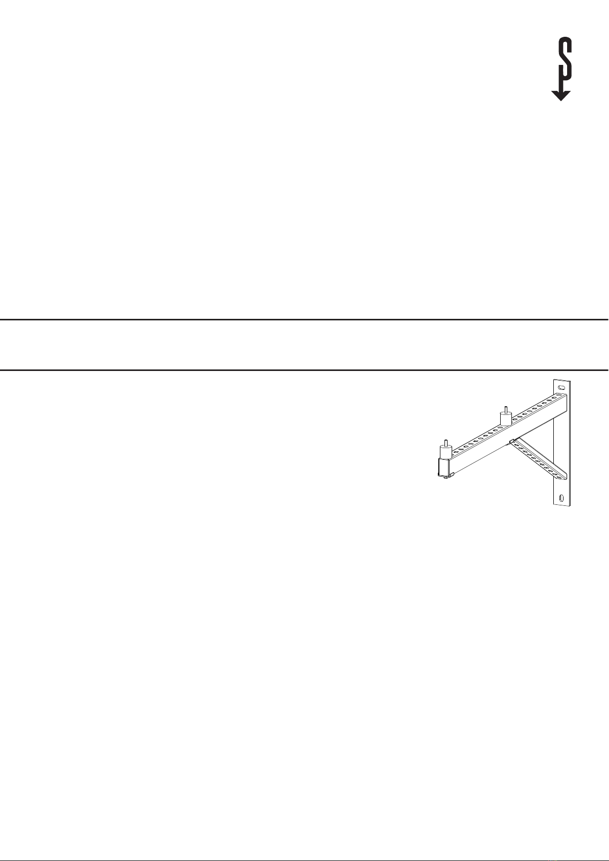
Montage
Hinweis
Um eine Störung durch Körperschallübertragungen
zu vermeiden, installieren Sie die Wandkonsole nicht
an den Außenwänden von Wohn- oder Schlafräumen.
Montieren Sie die Wandkonsole z.B. an einer Ga-
ragenwand.
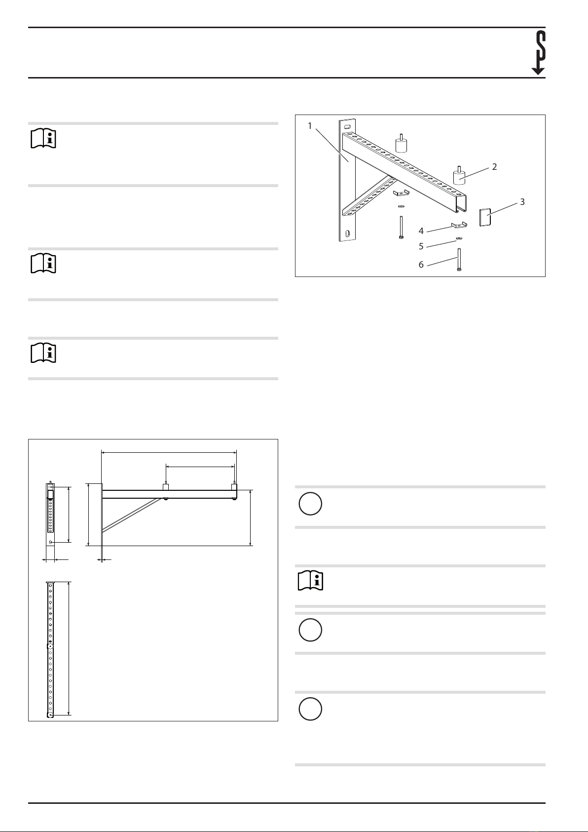
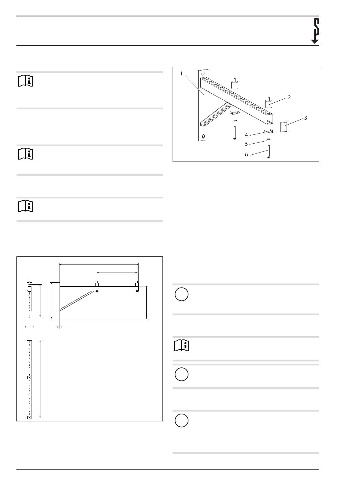
Hinweis
Um die Montage und die Wartung zu erleichtern, emp-
fehlen wir eine Einbauhöhe von max. 1m.
Markieren Sie die Position der Bohrlöcher an der Befes-
tigungswand, halten Sie hierzu die Wandkonsole in der
gewünschten Montagehöhe an die Wand.
!Sachschaden
Achten Sie darauf, dass beim Bohren keine Leitungen
beschädigt werden können.
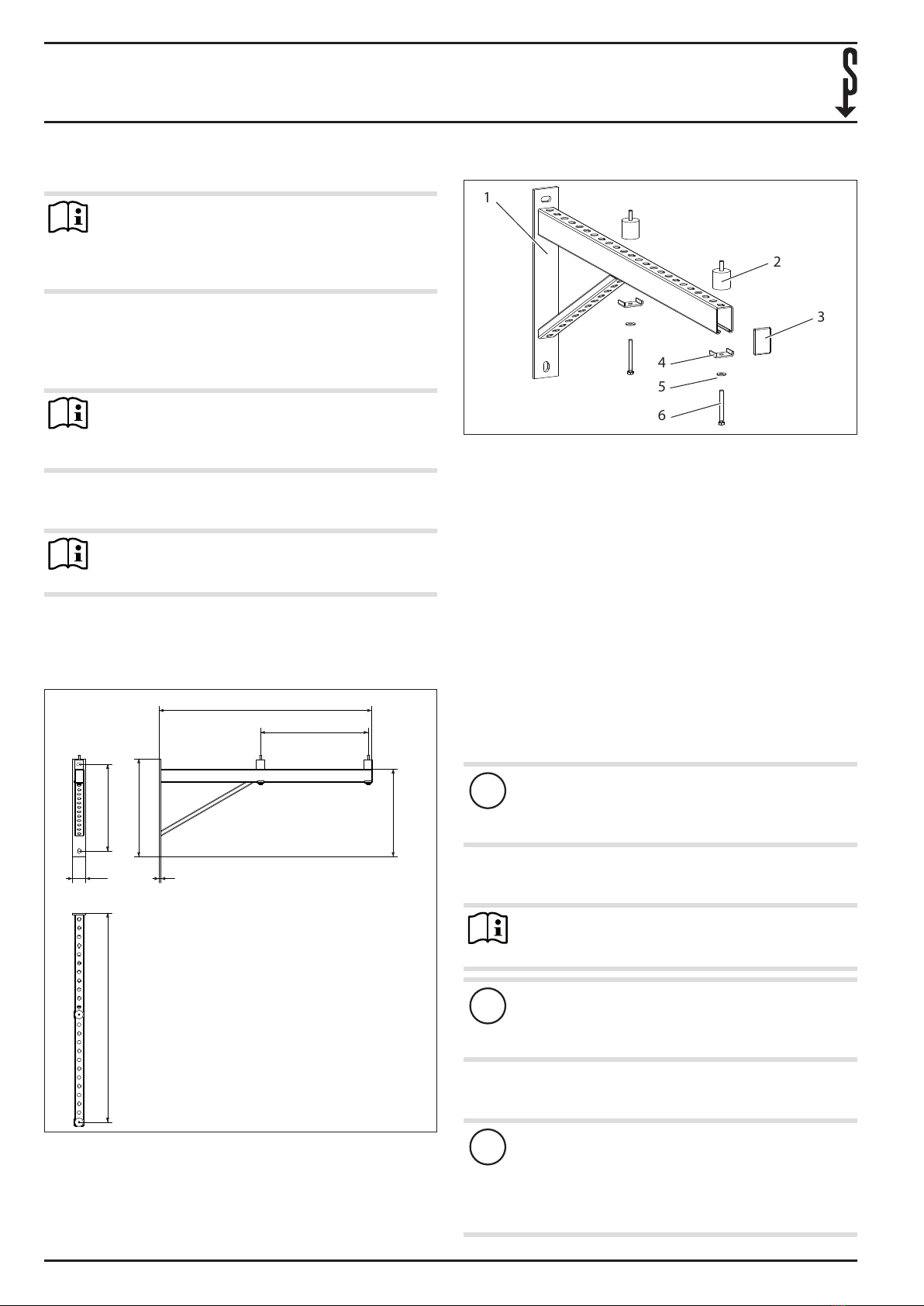
4. Montage
4.1 Befestigung an der Wand
Bohren Sie die Löcher.
Stecken Sie die Dübel in die Löcher.
Schrauben Sie die Wandkonsole an die Wand.
!Sachschaden
Stellen Sie sicher, dass die Wandkonsole bündig an der
Wand auiegt.
Prüfen Sie die Ausrichtung der Wandkonsole mit einer
Wasserwaage.
Richten Sie die Wandkonsole bei Bedarf durch Lockern
und Anziehen der Schrauben aus.
Ziehen Sie alle Schrauben mit einem Schraubenschlüssel
fest an.
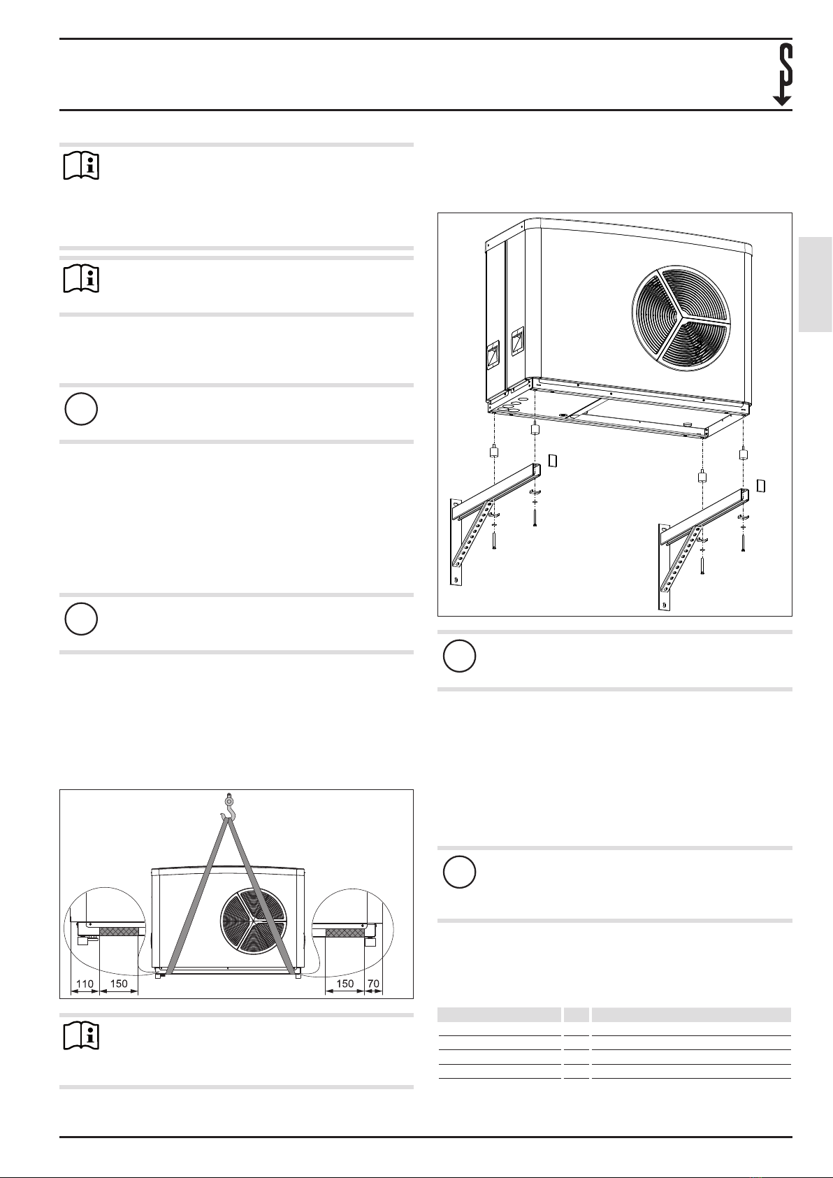
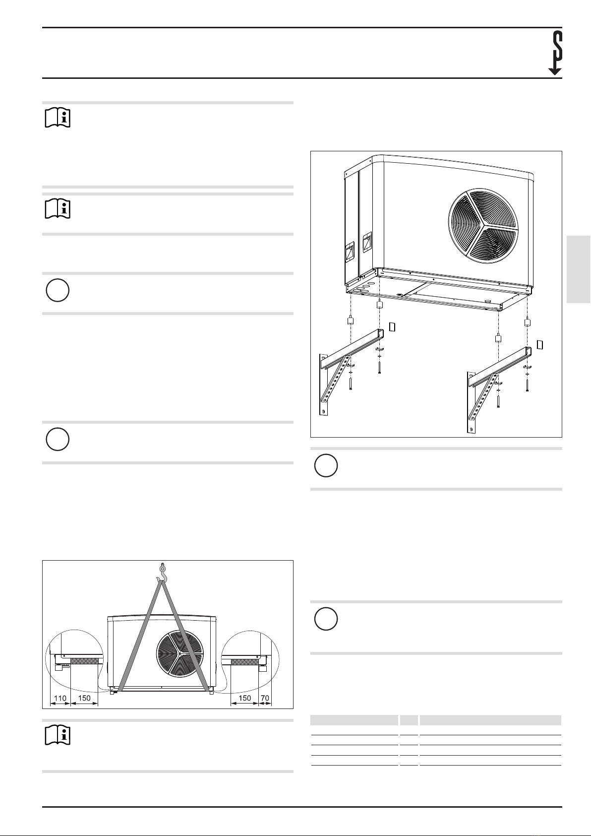
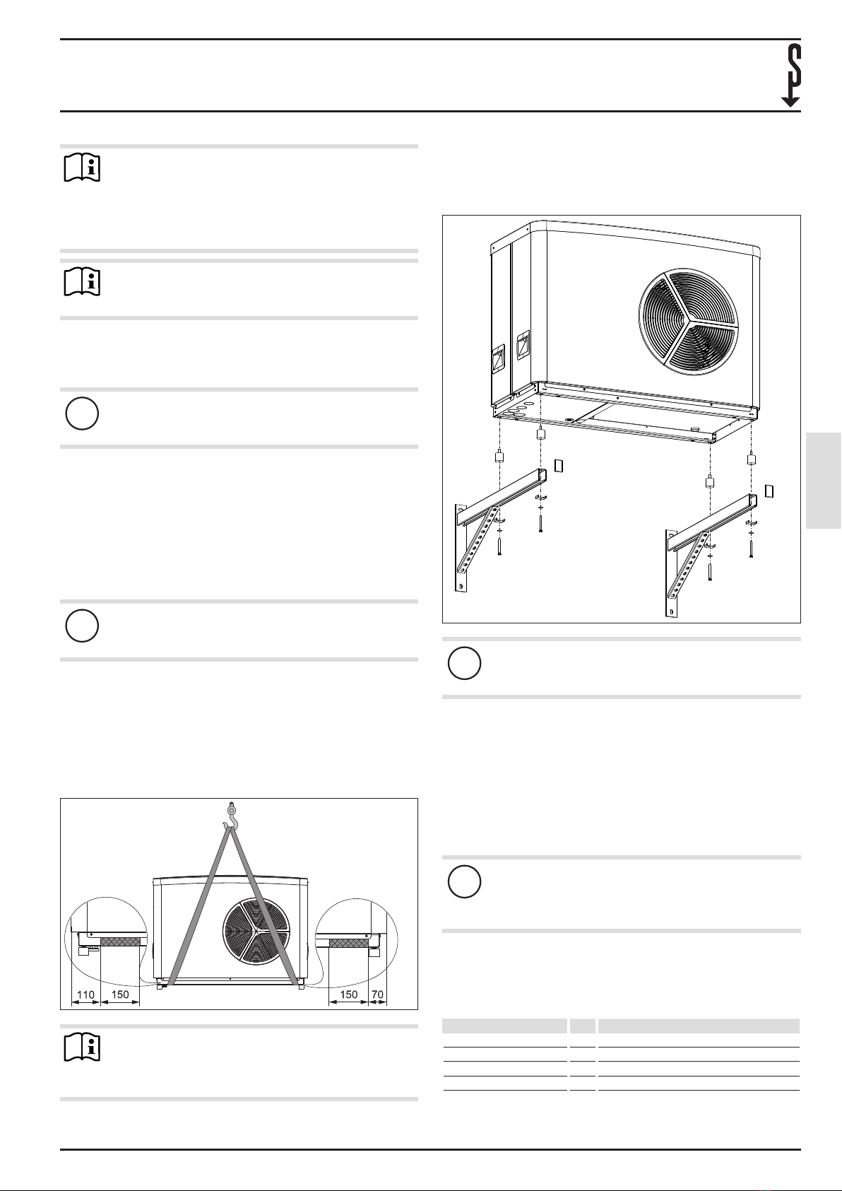
4.2 Befestigung des Außengerätes
26_03_01_1548
Hinweis
Tragegurte zum Transportieren des Gerätes können
Sie an den grau markierten Bereichen unten am Ge-
stellrahmen einhaken.
Schrauben Sie die Gerätefüße vom Außengerät ab. Entsor-
gen Sie die Gerätefüße.
Schrauben Sie die Gummipuer in die dargestellten Posi-
tionen am Außengerät hinein.
D0000055145
!Sachschaden
Achten Sie darauf, dass das Außengerät bei der Mon-
tage nicht von der Wandkonsole rutscht.
Setzen Sie das Außengerät mit den Gummipuern auf die
Wandkonsole.
Führen Sie die Schrauben mit den Unterlegscheiben und
den Halteklammern in die Gummipuer. Achten Sie dar-
auf, dass die Halteklammern quer zur Wandkonsole aus-
gerichtet sind.
Ziehen Sie alle Schrauben fest an.
Setzen Sie die Abschlusskappen auf die Enden der
Wandkonsole.
!Sachschaden
Lassen Sie die Installation von einem Fachhandwerker
prüfen, um sicherzustellen, dass eine dauerhafte und
sichere Aufstellung des Gerätes gewährleistet ist.
5. Technische Daten
5.1 Datentabelle
WK 2
234722
Schenkellänge mm 800
Gewichtsbelastung kg 175
Geeignet für 15/20/25 AC(S), HPA-O Premium