Disconnect the vehicle's negative battery cable before making any wire connections.
Protect all vehicle surfaces with tape or plastic.
Do not install components in any location that will hinder vehicle operation, such as
steering wheel, gearshift, air bags, hazard switch.
Bundle cables and harnesses with electrical tape or wire ties to prevent them from
interfering with moving parts.
Never attempt to disassemble or modify the product. Otherwise, an accident, re or
electric shock may result.
Exposed wires must be insulated with electrical tape. Otherwise, a short circuit, re, or
electric shock may result.
To prevent damage to the vehicle, conrm the locations of hoses, electrical wiring, and
the fuel tank prior to drilling holes to install this product.
When it is necessary to replace the fuse, always use a fuse of the correct rating
(number of amperes). Use of fuses with higher amperage ratings may cause a re.
PRECAUTIONS
Contents
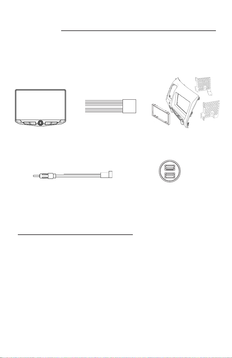
Stinger UN1810
10” Multimedia System
Kit Components............................................................... 3
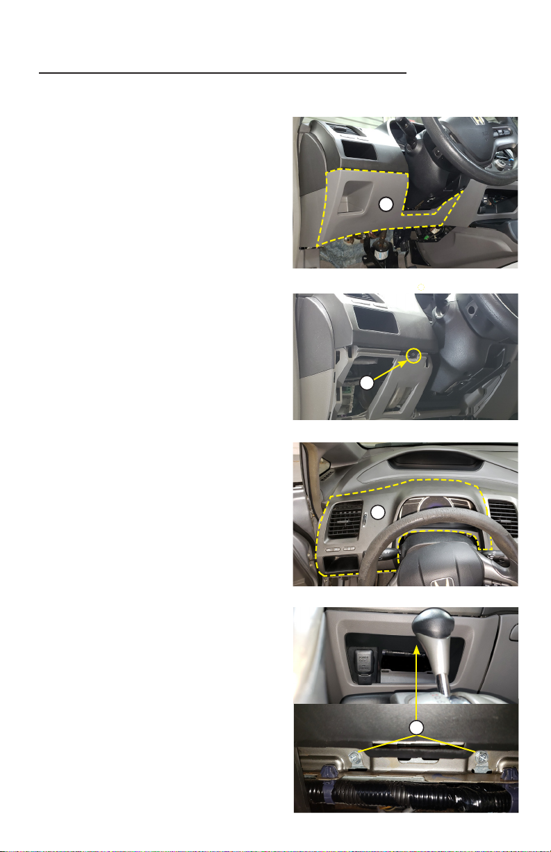
Vehicle Disassembly........................................................ 4
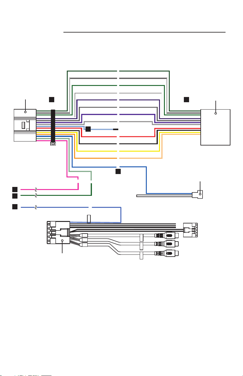
Wire Connections............................................................ 8
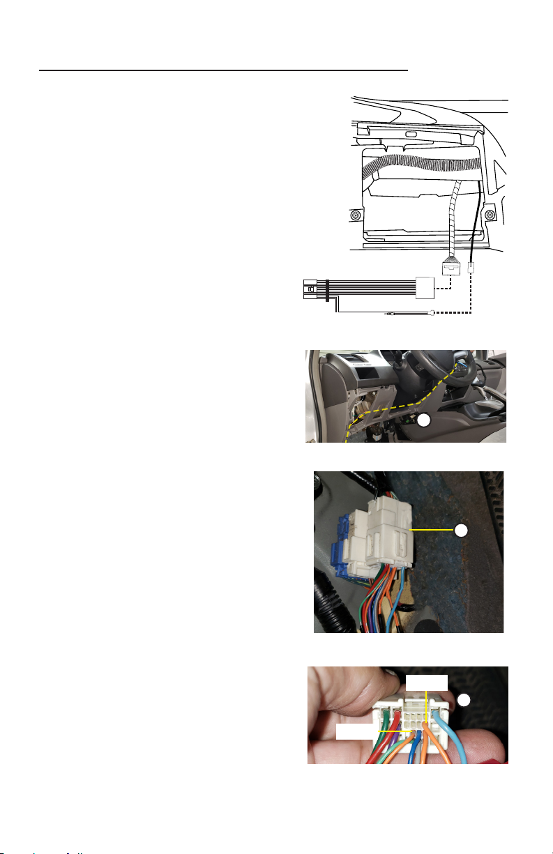
Vehicle Wire Connections.............................................. 10
GPS Antenna / USB Ports............................................. 12
Radio & Display Assembly............................................. 14
Radio/Panel Assembly....................................................16
Vehicle Installation......................................................... 18
Function Test................................................................. 21
Vehicle Reassembly...................................................... 22