Stinger CS150B User manual

OPERATION MAINTENANCE SAFETY WARRANTY
CS150B CAP STAPLER OWNER’S MANUAL
PLEASE READ! This manual contains important information about your new tool.
REV 7/8/19
ISANTA
MEMBER
SM

CS150B CAP STAPLER
Congratulations on purchasing the STINGER CS150B Cap Stapler! You have
selected a brand and a tool that you can count on to deliver best practice
installation, and perform job after job.
Please take the time to read and understand the information in this Owner’s Manual
before operating or maintaining your CS150B Cap Stapler.
The CS150B is intended for securing housewrap, foamboard, and roofing felt only.
Improper use of the CS150B could result in serious injury or even death. Most accidents
occur because of the failure to observe basic safety rules and precautions, which are
outlined in the “Important Information” section of this manual.
This Owner’s Manual should be available to anyone who plans to operate the CS150B.
Important Information
Tool Specifications
Loading the Tool
Operating the Tool
Schematic
Parts List
Maintenance and Storage
Warranty
Troubleshooting
Declaration of Conformity
1
3
5
6
7
8
10
11
12
13
TABLE OF CONTENTS

IMPORTANT INFORMATION
PERSONAL SAFETY ITEMS
• Do not use tool prior to reading the Owner’s Manual
• Always wear eye protection that conforms to ANSI requirements
(Z87.1) and provides protection against flying particles both from
the front and side. Eye protection should be worn by the operator
and by others in the work area. Eye protection is required to
protect against flying fasteners and debris that could possibly
cause severe eye injury.
• The employer is responsible to enforce the use of eye protection
equipment by the tool operator and all other personnel in the work
area.
• To prevent accidental injuries
- Handle the tool with care
- Always assume that the tool contains fasteners
- Always disconnect the air hose from the CS150B when:
• loading staples and/or caps
• performing inspection, maintenance or repair
• clearing a staple or collated cap jam
• the tool is not in use
• leaving the work area
• moving the CS150B to another work location
• handing the CS150B to another person
• storing the tool
- Never point the tool toward yourself or anyone else
- Never engage in horseplay
- Never hold or carry the tool with a finger on the trigger
- Never place a hand or any other part of the body in
the fastener discharge area of the tool while the air supply
is connected
1

IMPORTANT INFORMATION
AIR SUPPLY AND CONNECTIONS
• Use only clean, regulated compressed air as a power source for this tool. Do not use bottle
gases, combustible gases or oxygen as a power source for the tool as the tool may explode.
• Do not use air supply pressures that exceed 110 PSI (7.7 bar). Exceeding the recommended
maximum operating air pressure will greatly increase tool wear.
• The air supply must be capable of maintaining the operating air pressure of the tool. Pressure
drops in the air supply can reduce tool wear.
• Use a pressure regulator and gauge to allow visual inspection of the air pressure being
delivered to the tool.
• Use air hoses that have rated pressures of up to 150% of the maximum pressure that can be
generated by the power source. The supply hose should contain fittings that will provide quick
disconnecting from the male plug on the tool.
• Use quick connect fittings that allow the tool to be unhooked from the air supply quickly and
easily.
• Do not use fittings that will not allow the tool to exhaust when the air supply is disconnected.
2
OPERATION OF THE TOOL
• Never inspect, maintain, repair, adjust, clear a jam or store the tool with the air connected.
• Never use the tool in proximity of flammable gases or liquids, as some tools will create sparks
that can be an ignition source for a fire or explosion.
• Always inspect the safety device for damage and proper operation prior to operation.
• Never assume the tool is empty of fasteners.
• Never point the tool toward yourself or any other persons.
• Never cycle the tool unless it is in contact with the work-piece.
• Never use the tool as a hammer or wedging device or drop to the floor from any height.
• Always remove your finger from the trigger when pausing from cycling.
• Never tamper with the safety device or use the tool if the safety device is not functioning
properly.
• Use only STINGER® StaplePac® cap fasteners with the STINGER CS150B Cap Stapler. Never
use any fasteners that are not specified for use in this tool. The CS150B holds 1 coil of plastic
caps (200 caps) and 2 strips of staples (100 staples each).

TOOL SPECIFICATIONS
3
Operating Pressure
Weight
Staple Capacity
Cap Capacity
Air Inlet
Fasteners
Audio Data
Vibration Data
80 - 110 PSI*
4.2 lbs | 1.9kg
200 staples (2 - 100 count strips)
200 collated plastic caps (1 reel)
1/4” | 6.35mm
STINGER® StaplePac® only. Each 2000 count StaplePac
consists of 20 strips of 16mm, 22mm, 32mm & 38mm,
18 gauge staples (100 staples per strip) and 10 reels of
25mm diameter collated plastic caps (200 caps per reel).
Loudness levels presented in the table below are in
accordance with EN 792-13 (EN12549+A1:2008)
LpA 1s,1m = 86,7 dB(A)
LwA 1s = 99,7 dB(A)
LpA 1s, = 90,7 dB(A)
These levels are characteristic of the tool but does not
represent the sound that occurs at the point the tool is
used. Workstation design can reduce the noise levels, for
example by placing the work piece on sound absorbent
supports.
This value is in accordance with EN 792-13
(ISO 8662-11:1999)
Equivalent Vibration Value = ahv,eq (m/s2) = 3,3
This value is characteristic of the tool and does not
represent the effect of the hand-arm system when using
the tool.
*May require depth adjustment on tool depending on materials used and length of fastener used
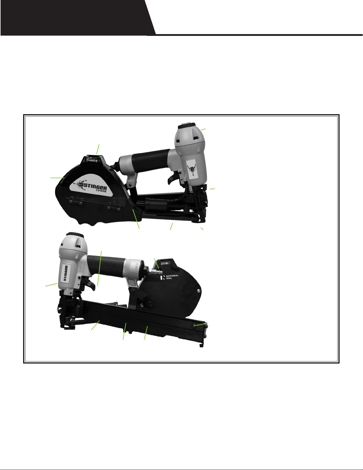
TOOL SPECIFICATIONS
1. Magazine
2. Magazine Cover
3. Cover Release Tab
4. Cap Feeder
5. Staple Track
6. Staple Follower
7. Catch Button
8. Latch
9. End Cap
10. Exhaust
11. Safety
12. Trigger
13. Nose
14. Quick Clear™ Lever
15. Feed Chute
1 / 2
3
4 15 11
12
13
14
10
5
6 8
7
9
4
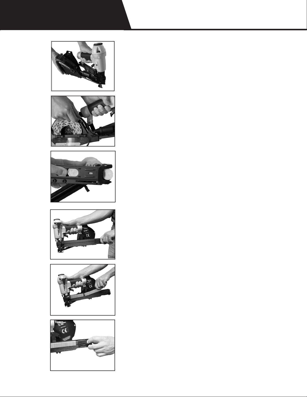
LOADING THE TOOL
• Disconnect air. Open the Magazine Cover.
• Place cap reel in the Magazine - make
sure the front end of the cap coil is placed
over the cap guide area of the Magazine.
Insert lead cap into the Feed Chute. Close
the Magazine Cover.
• Slide caps along the Feed Chute with
fingers until they engage the Cap Feeder.
Pull the Cap Feeder back and release to
advance the caps until the first cap is under
the Nose of the tool.
• Pull back the Staple Follower until the
Latch catches.
• Place staples in the Staple Track.
• Release the Catch Button. Plug into the air
source. The tool is ready to use!
5

OPERATING THE TOOL
DO NOT USE CS150B PRIOR TO READING THIS OWNER’S MANUAL
1. Read warning label(s) on the tool
2. Visually inspect the tool for worn or damaged parts
3. Wear appropriate eye and ear protection
4. Install a male pneumatic fitting into the End Cap of the tool, ensuring
that the fitting allows the tool to exhaust any air in the tool when the hose is
disconnected
5. Add 2 drops of non-detergent, 20-weight oil into the male fitting daily
6. Connect the air hose to the tool using a quick connect fitting, and check
the air pressure reading on the regulator to ensure it does not exceed 110 PSI.
Check the tool for any air leeks.
7. Place the tool, empty of fasteners, in operating position on a scrap work
piece - fully depress the Safety and pull the Trigger to verify that the
tool cycles.
8. Disconnect the air hose from the tool when:
• Loading staples and/or caps
• Performing inspection, maintenance, or repair
• Clearing a staple or collated cap jam
• The tool is not in use
• Leaving the work area
• Moving the tool to another work location
• Handing the tool to another person
• Storing the tool
9. Following recommended loading instructions, load the fastener approved
for use in the tool.
10. Cycle the tool on a scrap piece to evaluate the depth of penetration by
the fastener into the work piece.
11. To adjust the depth of penetration, regulate the air pressure at the air
compressor and/or disconnect the air hose, adjust the depth control wheel,
connect the air hose, and cycle the tool on a scrap work piece to evaluate the
adjustment.
12. Repeat Step 11 as needed to set the correct depth, using the minimum
amount of air pressure to drive the fastener.
6
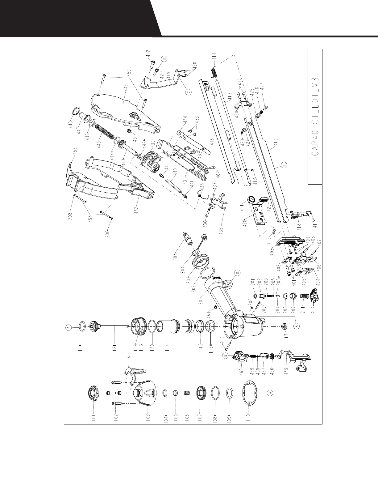
CS150B SCHEMATIC
contact Inside Sales at 800 - 746 - 5659 to place an order for replacement parts
7

CS150B PARTS LIST
8
Ref. # Description National Nail Item #
101 DEFLECTOR 0138500
102 BOLT ASSY 0138501
103 CAP 0138502
104 O - RING 0138503
105 SEAL 0138504
106 COMPRESSION SPRING 0138505
107 POPPET VALVE 0138506
108 O - RING 0138507
109 O - RING 0138508
110* GASKET 0138509
111* O - RING 0138510
112 DRIVER UNIT 0138511
113 O - RING 0138512
114 CYLINDER - ALUMINUM 0138639
115 CYLINDER RING 0138514
116* BUMPER 0138515
117* BLADE SEAL 0138516
118 BELT HOOK 0138517
119 COLLAR 0138640
120 O-RING 0138641
201 SEAL 0138518
202 TRIGGER VALVE HEAD 0138519
203 SPRING 0138520
204 PLUNGER 0138521
205 O - RING 0138522
205A O - RING 0138523
206 O - RING 0138524
207 TRIGGER VALVE GUIDE 0138525
208* RETAINER 0138526
209 SPRING PIN 0138527
210 TRIGGER PIVOT PIN 0138528
211 SPRING 0138529
212 TRIGGER UNIT 0138530
301 GUN BODY UNIT 0138531
302 O - RING 0138532
303 END CAP 0138533
304 DUSTY COVER 0138534
305 AIR PLUG 0138535
401 BOLT ASSY 0138536
402 DRIVER GUIDE COVER B 0138537
403 DRIVER GUIDE 0138538
404 LOCK HANDLE UNIT 0138539
405 PUSHER CUSHION 0138540
406 DRIVER GUIDE COVER A 0138541
407 SPIRAL PINS 0138542
408 FIXED PIN 0138543
409 HEX.SOC.HD.BOLT 0138544
410 MAGAZINE 0138545
411* SPRING 0138546
412* SPRING RETAINER 0138547
413 ROD 0138548
*Indicates
commonly
replaced part
Table of contents
Languages:
Other Stinger Power Tools manuals


