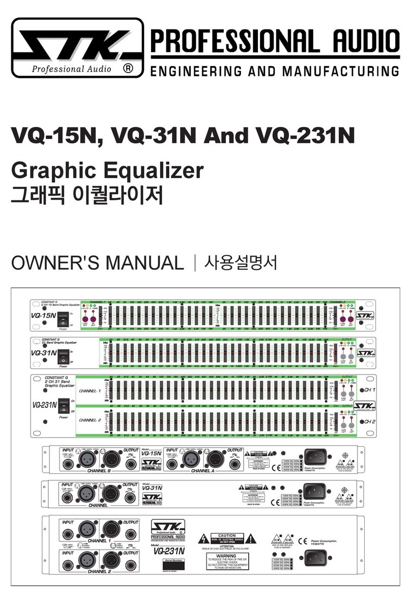
STK Professional Audio HVQ Series User manual

HVQ-215, HVQ-131, HVQ-231
HVQ 시리즈 그래픽 이퀄라이저
사용설명서
HVQ Series Graphic Equalizer
OWNER'S MANUAL
HVQ-131
Equalizer/
Comp limiter
+6/+15 dB
-6/ -15 dB
+6/+15 dB
-6/ -15 dB
Noise
Reduction
Range Low Cut
EQ
ByPass
Output Level Gain Reduction
(dB)
(dBu)
Clip
±
6dB
±
15dB
+18
+10
0
-10
10
6
3
1
Input Gain Comp & Limiter
Threshold
+6
4
3
2
1
+0.5
0
- 0.5
1
2
3
4
- 6
+15
12
9
7
6
4
+1
2
0
-1
4
2
7
9
12
-15
6
+6
4
3
2
1
+0.5
0
- 0.5
1
2
3
4
- 6
+15
12
9
7
6
4
+1
2
0
-1
4
2
7
9
12
-15
6
15 18
11
8
5
1
4
dBu
OFF
20
C
O
M
P
5
:
1
R
A
N
G
E
L
I
M
I
T
E
R
R
A
N
G
E
0+2
+4
-2
-4
-7
-10
-12
dB
+12
+10
+8
CH A
CH B
Noise
Reduction
HVQ-231
Equalizer/
Comp limiter
Range Low Cut
EQ
ByPass
Output Level Gain Reduction
(dB)
(dBu)
Clip
±
6dB
±
15dB
+18
Input Gain
Comp & Limiter
Threshold
+10
0
-10
10
6
3
1
Noise
Reduction
Range Low Cut
EQ
ByPass
Output Level Gain Reduction
(dB)
(dBu)
Clip
±
6dB
±
15dB
+18
Input Gain
Comp & Limiter
Threshold
+10
0
-10
10
6
3
1
+6/+15 dB
-6/ -15 dB
+6/+15 dB
-6/ -15 dB
+6/+15 dB
-6/ -15 dB
+6/+15 dB
-6/ -15 dB
+6
4
3
2
1
+0.5
0
- 0.5
1
2
3
4
- 6
+15
12
9
7
6
4
+1
2
0
-1
4
2
7
9
12
-15
6
+6
4
3
2
1
+0.5
0
- 0.5
1
2
3
4
- 6
+15
12
9
7
6
4
+1
2
0
-1
4
2
7
9
12
-15
6
+6
4
3
2
1
+0.5
0
- 0.5
1
2
3
4
- 6
+15
12
9
7
6
4
+1
2
0
-1
4
2
7
9
12
-15
6
+6
4
3
2
1
+0.5
0
- 0.5
1
2
3
4
- 6
+15
12
9
7
6
4
+1
2
0
-1
4
2
7
9
12
-15
6
15 18
11
8
5
1
4
dBu
OFF
20
C
O
M
P
5
:
1
R
A
N
G
E
L
I
M
I
T
E
R
R
A
N
G
E
0+2
+4
-2
-4
-7
-10
-12
dB
+12
+10
+8
15 18
11
8
5
1
4
dBu
OFF
20
C
O
M
P
5
:
1
R
A
N
G
E
L
I
M
I
T
E
R
R
A
N
G
E
0+2
+4
-2
-4
-7
-10
-12
dB
+12
+10
+8
25 40 63 100 160 250 400 630 1K 1.6K 2.5K 4K 6.3K 10K 16K 25 40 63 100 160 250 400 630 1K 1.6K 2.5K 4K 6.3K 10K 16K
CHANNEL A CHANNEL B
25 40 63 100 160 250 400 630 1K 1.6K 2.5K 4K 6.3K 10K 16K 25 40 63 100 160 250 400 630 1K 1.6K 2.5K 4K 6.3K 10K 16K
CHANNEL A CHANNEL B
HVQ-215
Range Low Cut EQ
ByPass
Output Level Gain Reduction
(dB)
(dBu)
Clip
Range Low Cut EQ
ByPass
Output Level Gain Reduction
Clip
±
6dB
±
15dB
+18
Input Gain Comp & Limiter
Threshold Input Gain Comp & Limiter
Threshold
Equalizer/
Comp limiter
+6/+15 dB
-6/ -15 dB
+6/+15 dB
-6/ -15 dB
+10
0
-10
10
6
3
1
0
+3-3
-6
-9
-12
dB
+12
+9
+6
0
+3-3
-6
-9
-12
dB
+12
+9
+6
(dB)
(dBu)
±
6dB
±
15dB
+18
+6/+15 dB
-6/ -15 dB
+6/+15 dB
-6/ -15 dB
+10
0
-10
10
6
3
1
15
18
11
8
5
0
1
dBu
OFF
20
C
O
M
P
5
:
1
R
A
N
G
E
+6
4
3
2
1
+0.5
0
- 0.5
1
2
3
4
- 6
+15
12
9
7
4
+1
2
0
-1
4
2
7
9
12
-15
+6
4
3
2
1
+0.5
0
- 0.5
1
2
3
4
- 6
+15
12
9
7
4
+1
2
0
-1
4
2
7
9
12
-15
+6
4
3
2
1
+0.5
0
- 0.5
1
2
3
4
- 6
+15
12
9
7
4
+1
2
0
-1
4
2
7
9
12
-15
+6
4
3
2
1
+0.5
0
- 0.5
1
2
3
4
- 6
+15
12
9
7
4
+1
2
0
-1
4
2
7
9
12
-15
L
I
M
I
T
E
R
R
A
N
G
E
15
18
11
8
5
0
1
dBu
OFF
20
C
O
M
P
5
:
1
R
A
N
G
E
L
I
M
I
T
E
R
R
A
N
G
E
http://stk.com.vn

2
HVQ-215, HVQ-131, HVQ-231
HVQ 시리즈 그래픽 이퀄라이저
HVQ Series Graphic Equalizer
Table of Contents
l
목 차
1. Introduction l 제품 소개........................................................................................................................................
3
2. Important Safety Instructions l 안전을 위한 주의 사항.....................................................................
4-5
3. Operation and Application Notes l 기기의 동작과 EQ에 대한 참고사항..................................
6-7
4. Panel Descriptions l 각 부의 명칭 .................................................................................................................
8-12
5. Installation Considerations l 설치 주의사항 ..........................................................................................
13-15
6. System Hookup Diagrams l 시스템 연결 구성도 ................................................................................. 16-17
7. Block Diagram l 회로의 구성도.........................................................................................................................
18-20
8. Specications l 제품 규격...................................................................................................................................
21-24
9. Warranty Information l 제품 보증에 대해서 ..............................................................................................
25-a,b
http://stk.com.vn

3
1. Introduction
l
제품 소개
Congratulations, and thank you for your purchasing
of STK HVQ series EQ. STK HVQ equalizers offer
versatile feature-packed to professional performance
in a compact and economical format for the musician,
performer, studio engineer, and sound contractor. Each
equalizer allows the user to see a graphic representation
of the equalization applied to the audio spectrum, and
offers the exibility for solutions of many EQ problems.
The HVQ-215 is 2/3 octave dual 15 band, HVQ-131 is
1/3 octave single 31 band, and HVQ-231 is 1/3 octave
dual 31 band. These units featured 6dB and 15dB cut
or boost per band with low cut lter for each channel.
The products have built-in noise reductoin(HVQ-215
is optional) and on board comp limiter with variable
threshold control. The 45mm long throw, high resolution
faders allow precise adjustment of each constant Q
band. All inputs, outputs are XLR balanced and 1/4"
balanced connectors, the STK HVQ equalizers ability
to increase sound quality of almost high class sound
systems. While providing powerful, accurate and reliable
performance along with outstanding value, your HVQ
series equalizer has been designed for many years of
dependable service. Please take the time to read this
manual before operation so that you fully understand the
features and correct use to this ne product.
STK의 멋진 HVQ시리즈 이퀄라이져를 구입하신 것을
감사드리며 훌륭한 제품을 구매하신 것을 축하드립니다.
STK의 HVQ 이퀄라이져는 폭넓은 용도의 컴팩트하고
경제적인 포맷으로 프로페셔널한 성능을 갖추고 있어 뮤
지션, 가수, 스튜디오 엔지니어 그리고 사운드 시공분야
에 널리 채택되고 있습니다. 본 제품들은 가청대역의 저
주파 스펙트럼 분포를 응용하여 사용자에게 균일한 오
디오 사운드를 만들어주며, 다양한 수 많은 종류의 고르
지 못한 불균등한 음향을 유연한 성능으로 해결해줍니다.
HVQ-215는 듀얼 2/3옥타브타입, HVQ-131은 싱글
1/3옥타브타입, HVQ-231은 듀얼 1/3옥타브 타입의 이
퀄라이져입니다.
이 제품들의 특징은 각 채널별로 해당 주파수에 대해
6dB 혹은 15dB 의 이득을 부스트 및 커트할 수 있으며
로우컷 필터를 함께 보유하고 있습니다. 과도한 게인 증
가에 따른 노이즈 리덕션(HVQ-215는 옵션사항) 기능과
모든 입력 범위를 제어해주는 가변 스레숄드 타입의 컴프
리미터 장치가 추가되었습니다. 각 밴드별 컨스턴트 큐
값의 정밀한 조절을 위해 하이클래스의 45mm타입의 고
품격 슬라이드 볼륨을 채택하고 있습니다. 모든 입력과
출력부는 고품질의 XLR 밸런스드 타입 잭과 더불어 1/4
인치 폰 잭을 함께 사용할 수 있습니다. 따라서 HVQ이퀄
라이져는 대부분의 하이 클래스 사운드 시스템에 대한 사
운드 품질을 높일 수 있는 가장 적합한 제품입니다. 기존
의 가치를 넘어서는 더욱 파워풀하고 정확하며 신뢰할 만
한 성능을 제공하기 위해서 STK HVQ 시리즈 이퀄라이
져는 수년간의 연구를 거듭하여 설계되었습니다. 제품을
동작시키기 전에 이 사용서를 꼭 읽어보시고 이해하시어
올바르게 제품을 사용해주시기 바랍니다.
http://stk.com.vn

1. Read Instructions
All the safety and operating instructions should be read before
the appliance is operated.
2. Retain Instructions
The safety and operating instructions should be retained for
future reference.
3. Heed Warnings
All warnings on this appliance and in the operating
instructions should be adhered to.
4. Follow Instructions
All instructions should be followed.
5. Water and Moisture
This appliance should not be used near water- for example,
near a bathtub, sink, laundry tub, in a wet basement, near a
swimming pool, etc.
6. Heat
This appliance should be situated away from heat sources such
as radiators, heat registers, stoves, or other appliances (including
ampliers) that produce heat.
7. Power Sources
This appliance should be connected to a power supply only
of the type described in the operating instructions or as
marked on the appliance. If you are not sure of the type of
power supply to your home, consult your appliance dealer
or local power company. For appliances intended to operate
from battery power, or other sources, refer to the operating
instructions.
8. Polarization
If the appliance is equipped with a polarized alternating-
current line plug (a plug having one blade wider than the
other), this plug will t into the power outlet only one way.
This is a safety feature. If you are unable to insert the plug
fully into the outlet, try reversing the plug. If the plug should
still fail to t, contact your electrician to replace your obsolete
outlet. Do not defeat the safety purpose of the polarized plug.
9. Grounding
If the appliance is equipped with a 3-wire grounding-type
plug, a plug having a third (grounding) pin, this plug will only
t into a grounding-type power outlet. This is safety feature.
If you are unable to insert the plug into the outlet, contact
your electrician to replace your obsolete outlet. Do not defeat
the safety purpose of the grounding-type plug.
10. Power Cord Protection
Power supply cords should be routed so that they are not
likely to be walked on or pinched by items placed upon or
against them, paying particular attention to cords at plugs,
convenience receptacles, and the point where they exit from
the appliance.
1. 사용 설명서를 꼭 읽어주세요
제품을 사용하기 전에 본 설명서의 안전과 작동에 관한 모든 기능
설명들을 반드시 읽어 보십시오.
2. 사용 설명서를 잘 보관하세요
안전과 작동에 관한 설명은 나중에 참고하게 될 경우가 있으므로
잘 보관해서 유용하게 사용하십시오.
3. 주의 및 경고사항
사용 설명서에 나타나 있는 모든 주의사항들은 반드시 지켜야 합니
다.
4. 사용법을 지켜주세요
본 설명서의 사용법에 관한 모든 내용들은 반드시 지켜야 합니다.
5. 수분과 습기주의
제품은 물기 또는 습기가 많은 곳에 설치하면 감전의 원인이 됩니
다. (욕조, 세면기, 부엌, 세탁기, 젖은 바닥, 수영장의 풀 근처, 습
지 등)
6. 열주의
제품은 전열기구 혹은 열을 발생하는 그 밖의 기구들로부터 떨어진
곳에 설치되어야 합니다. 설치 전 반드시 주변을 확인하시어 건조
한 장소에 제품을 설치해 주십시오.
7. 전원주의
이 제품은 반드시 사용 설명서에 정해진 타입의 전원 또는 본체에
표시된 전원에 연결되어야 합니다. 만약 사용하려는 전원이 확실치
않을 때는 전원 기구 판매자나 전원 공급자에게 문의하세요. 공급
되는 전원이 축전지 형태이거나 다른 방식이라면 제품 사용을 피해
주세요.
8. 분극 플러그에 대한 주의
만약 전원기구가 극성이 있는 교류전원이라면(플러그 중 한 블레이
드가 다른 것에 비해 넓게 되어 있습니다.) 이 플러그는 오직 한 가
지 방법으로 전원 아울렛에 끼워져야 합니다. 이것이 안전한 모습
입니다. 만약 플러그를 올바르게 끼울 수 없다면 플러그를 빼고 다
시 시도해 보세요. 만약 그래도 안 된다면 전원 아울렛을 교체하도
록 전기 기사에게 문의하세요. 분극 플러그에 대한 주의사항을 반
드시 지켜주세요.
9. 접지 플러그에 대한 주의
만약 전원기구가 3선 접지 타입의 플러그라면 세번째핀(접지핀)을
가지고 있을 것입니다. 이 플러그는 반드시 접지 타입 전원 아울렛
에 맞게 끼워져야 합니다. 이것이 안전한 모습입니다. 만약 이 플러
그를 전원아울렛에 올바르게 끼울 수 없다면 전원 아울렛을 교체하
도록 전기기사에게 문의하세요. 접지 플러그에 대한 주의사항을 반
드시 지켜주세요.
10. 전원 코드의 보호
전원 공급 코드는 플러그, 콘센트, 그리고 본 제품과 연결되는 지점
들에 특별한 주의를 기울이면서 정확한 방향으로 꽂혀야 합니다.
그렇지 못한 경우에는 화재 및 제품 손상의 원인이 될 수 있습니다.
4
2. Important Safety Instructions
l
안전을 위한 주의 사항
http://stk.com.vn

11. Damage Requiring Service
Unplug this appliance from the wall outlet and refer servicing
to qualied service personnel under the following conditions:
a. When the power-supply cord or plug is damaged.
b. If liquid has been spilled, or objects have fallen into the
appliance.
c. If the appliance has been exposed to rain or water.
d. If the appliance does not operate normally by following
the operating Instructions. Adjust only those controls
that are covered by the operating instructions as an
improper adjustment of other controls may result in
damage and will often require extensive work by a
qualied technician to restore the appliance to its normal
operation.
e. If the appliance has been dropped or the cabinet has
been damaged.
f. When the appliance exhibits a distinct change in
performance-this indicates a need for service.
12. Servicing
Do not attempt to service this appliance yourself as opening
or removing covers may expose you to dangerous voltage
or other hazards. Refer all servicing to qualied service
personnel.
11. 제품 손상 수리 서비스
본 제품에 다음과 같은 경우가 발생했을 때, 전문가에 의해서만 수
리를 받을 수 있습니다.
가. 전원공급 코드 혹은 플러그가 손상되었을 경우.
나. 제품 안으로 이 물질이 떨어졌거나 액체가 스며들었을 경우.
다. 제품이 빗물이나 물에 젖었을 경우.
라. 제품이 정상적으로 작동하지 않을 경우 사용설명서에 나와
있는 내용들을 조정해 보세요. 사용 설명서 외의 내용을 조
정할 경우 더 큰 고장의 원인이 될 수 있습니다.
마. 제품이 바닥에 떨어졌을 경우나 본체에 손상이 갔을 경우.
바. 제품이 작동 시 서비스를 필요로 하는 두드러진 변화를 보일
경우.
12. 서비스
직접 제품을 분해하거나 커버를 벗겨낼 경우 감전 등 여러 위험을
초래할 수 있습니다. 반드시 모든 서비스는 본사의 직원에게 문의
해 주세요.
5
2. Important Safety Instructions
l
안전을 위한 주의 사항
http://stk.com.vn

3. Operation and Application Notes
l
기기의 동작과 EQ에 대한 참고사항
The HVQ series graphic equalizers are useful audio signal
processing tools in situations where precise frequency control
is required across the audible frequency spectrum.
When used with an audio spectrum analyzer the EQs can
tune any acoustical environment - from the studio to the
concert hall - to stop ringing, increase clarity, and atten
the overall frequency response of the environment. A real-
time spectrum analyzer or other types of audio environment
analyzers are very useful in determining the amount of
equalization needed.
Insert the graphic equalizer between the signal source
(usually a mixer) and the power ampliers (or the crossover
if there is one). Adjust the level and equalization as required
to yield the desired system response. The long throw faders
of the EQs allow very precise settings of the equalization for
accurate equalization curves.
For optimum signal-to-noise response, the gain structure of
the sound system must be properly set up.
Each component of the sound system should be set at its
nominal operating level, starting with the rst element in the
system, usually a mixing console. Each element should be
run at its nominal operating level in order to take advantage
of the maximum signal-to-noise properties of that element.
Loudspeaker ampliers, as the last element in the chain,
should be set only as loud as necessary, in order to avoid
inducing unnecessary noise into the system.
All active equalizers, by nature of design, add noise when
boosting of cutting that can easily degrade the otherwise
acceptable signal-to-noise ration of a sound system. Drastic
equalization can result in a loss of 20 dB or more signal-to-
noise. HVQ type noise reduction was engineered specically
for applications such as this. It provides up to 20dB of noise
reduction, thus restoring the dynamic range necessary for
even the most demanding professional sound systems. The
combination of proper wiring, proper gain structure and
noise reduction should render your sound system virtually
noise free.
HVQ 시리즈 그래픽 이퀄라이저는 오디오-음향시스템의 정밀한
주파수 컨트롤이 요구되는 현장에서 매우 필요한 전문 시그널 프로
세싱 기기입니다.
HVQ EQ를 오디오 스펙트럼 아날라이저와 함께 사용하게 되면 어
떤 어쿠스틱 환경(스튜디오에서 콘서트 홀까지)에서도 소리울림을
멈추고, 음색을 더욱 맑게 해주고 전체적인 주파수 응답을 고르게
해주는 등 완벽한 사운드를 튜닝할 수 있게 해줍니다. 실시간 스펙
트럼 아날라이저나 다른 타입의 환경 아날라이저는 어느 정도의 이
퀄라이징이 필요한지를 판단 할 수 있게 해주므로 매우 유용합니
다.
HVQ 그래픽 이퀄라이저는 입력 신호기기(일반적으로 믹서)와 파
워 앰플리파이어(또는 보유하고 있는 크로스 오버) 사이에 설치하
면 됩니다. 그리고 HVQ EQ의 주파수 조정과 적절한 음량을 맞추
게 되면 오디오 음향시스템의 현장 음향 디자인이 완료되게 됩니
다. HVQ EQ는 현장 음향 디자인의 보다 정확한 이퀄리제이션 커
브와 보다 정밀한 셋팅을 가능케 하기위해서 고품질 롱 스로우 페
이더를 체택하고 있습니다.
최적의 신호 대 잡음비를 위해 사운드 시스템의 게인 구조는 올바
르게 셋팅 되어야 합니다.
사운드 시스템의 기기들, 즉 시스템의 첫 번째 시작인 믹싱콘솔
(보통의 경우)의 각 입출력 신호 레벨은 표준동작으로 세트되어야
합니다. 이것은 최상의 신호 대 잡음비 특성을 얻기 위해 필요합니
다. 그리고 시스템 연결 고리의 마지막 요소인 라우드스피커 앰플
리파이어는 시스템 내에 불필요한 잡음이 섞이지 않도록 오직 필요
한 만큼의 크기로 세트되어야 합니다.
모든 액티브 이퀄라이저는 본질적인 설계는, 시스템의 신호를 부스
트 및 컷팅하는 과정에서 허용범위내에서 신호대 잡음비가 떨어질
수 있습니다. 과도한 이퀄리제이션은 20dB 이상의 신호 대 잡음비
손실을 가져옵니다. HVQ 타입 노이즈 리덕션은 이러한 부분을 위
해 설계되었습니다. 20dB의 노이즈 리덕션을 제공하므로 대부분
의 프로페셔널 사운드 시스템이 원하는 다이나믹 레인지를 되찾게
해 줍니다. 적절한 와이어 연결, 게인 구조 그리고 노이즈 리덕션은
사운드 시스템을 노이즈로부터 자유롭게 해 줄 것입니다.
6
http://stk.com.vn

1/3RD 옥타브와 2/3RD 옥타브 이퀄라이저
대부분의 그래픽 이퀄라이저는 가청 주파수 범위를 한 옥타브 당
3개의 대역(밴드)으로 나오거나 2개의 옥타브를 3개의 대역(밴드)
으로 나누어 다루고 있습니다. 하나의 옥타브는 주파수 대역 1~2
개 정도의 범위를 커버합니다. 예를 들어 50Hz ~100Hz 주파수 대
역을 하나의 옥타브라고 했을 때, 10개의 옥타브는 가청 주파수 영
역, 즉 20Hz ~20kHz까지를 커버합니다. 만약 각 10개의 옥타브
가 3개로 나뉜다면, 30개의 옥타브 또는 주파수 대역(밴드)을 얻
을수 있습니다. (STK 이퀄라이저의 31개의 대역은 20Hz와 가청
주파수 범위의 끝인 20kHz 모두를 포함합니다.) 1/3rd 옥타브의
이퀄라이저는 한 옥타브 범위에 3개 대역이 있다는 것을 뜻하며,
2/3rd 옥타브의 이퀄라이져는 두 옥타브 범위에 3개의 대역(밴드)
이 있다는 것을 뜻합니다.
그러므로 2/3rd 옥타브 이퀄라이저의 한 대역은 1/3rd 옥타브 이
퀄라이저의 한 대역보다 그 범위가 2배 더 넓습니다. 그래서 2/3rd
옥타브 이퀄라이저의 어떠한 대역(밴드)의 부스팅이나 컷팅은 더
넓은 범위의 주파수 영역에 영향을 끼치게 됩니다.
1/3rd 이퀄라이저의 슬라이더 밴드(대역폭)는 다루는 주파수 범위
가 가장 좁아서 매우 정밀합니다.
때문에 전체 가청 주파수 영역을 커버하기 위해서는 랙 패널 너비
공간을 모두 차지하는 31개의 슬라이더(주파수 밴드)가 필요하며,
적절하게 조절할 수 있는 시간이 필요합니다. 열악한 공간의 어쿠
스틱, 열악한 스피커반응, 오디오 시스템의 약점 등을 보완하기 위
해 1/3rd옥타브 그래픽 이퀄라이저를 설정할 때, 높은 해상도의
실시간 오디오 스펙트럼 분석기는 매우 유용한 장비입니다.
2/3rd 옥타브가 1/3rd만큼 정밀하지 못한 반면에 신호를 조작하는
데 걸리는 시간을 더욱 단축시켜 줄 수 있습니다. 또한, 보다 많은
주파수범위를 밴드별 EQ로 운영할 수 있습니다. 2/3rd 옥타브 EQ
는 음악이나 사운드 리인포스먼트 시스템(SR system)의 음향을 더
욱 쉽고 빠르게 조정 할 수 있습니다.
3. Operation and Application Notes
l
기기의 동작과 EQ에 대한 참고사항
FOR 1/3RD OCTAVE OR A 2/3RD OCTAVE EQUALIZER
Most graphic equalizers divide up the audio frequency range
into 1/3RD octave or 2/3rds octave pieces. One octave covers
a 2-to-1 range of frequencies. For example the frequency
range form 50 to 100 Hz is one octave. The audio frequency
range covers 10 octaves from 20Hz to 20KHz. If each of the
ten cotaves is divided into thirds. You get 30pices, or bands,
of frequency. (The 31 bands on STK equalizers result from
including both 20Hz and 20KHz bands on the ends of the
audio frequency range). A 1/3 octave equalizer means that 3
bands span 1 octave, while a 3/2 octave equalizer means that
3 bans span 2 octaves.
Therefore, one band on a 2/3 octave equalizer is twice as
wide as one band on a 1/3 octave equalizer, So, boosting or
cutting any band will affect a wider range of frequencies one
the 2/3 octave equalizer.
A 1/3RD octave equalizer is the most precise because you're
working with a narrower frequency range per band or slider
on the equalizer. To cover the entire audio range, you need 31
bands or sliders, which normally take up the entire width of
a rack panel, and take some time to adjust properly. A high -
resolution real time audio spectrum analyzer is a very useful
tool when setting up a 1/3RD octave graphic equalizer to
compensate for poor room acoustics, poor speaker response,
or the deciencies of an audio system.
While the 2/3rds octave is not as precise as a 1/3RD it takes
far less time to equalize a signal with this unit. And allows
more channels of EQ to be reached. The 2/3rds octave EQ
allows you to quickly and easily modify a sound for use in
music, or sound reinforcement.
7
http://stk.com.vn

8
Ⅰ Introduction
l
제품 소개
FRONT PANEL SECTION
1. 입력 조절기
이퀄라이져의 입력신호 레벨을 조절합니다. 입력 게인(이득)을
-12dB 에서 +12dB범위까지 변화시킬수 있으며 신호레벨 크기는
바 그래픽 출력레벨메타로 표시됩니다. EQ의 각 밴드 별 부스트와
컷으로 인한 게인(이득) 변화에 대한 전체적인 메인 출력레벨을 조
절하는데 사용하세요.
2. 부스트/컷 레인지 선택 스위치와 표시등
이 스위치는 ±6dB 또는 ±15dB 두 개의 부스트/컷 범위 중 이퀄
라이저가 사용할 것을 선택하는 스위치입니다. 매우 정밀한 부스
트/컷 조절을 원한다면 ±6dB 레인지를 선택하세요.
±15dB 범위가 선택될 경우 붉은색 표시등이 ±6dB범위 선택 시
노란색 표시등이 점등됩니다.
부스트/컷 스위치는 서서히 꺼집니다. 이는 다른 사운드 시스템에
손상을 줄 수 있는 경우를 방지하기 위해서입니다.
4. Panel Descriptions
l
각 부의 명칭
1. Input Gain Control
This control sets the signal level to the equalizer. It is
capable of -12dB to +12dB of gain. The signal level amounts
indicated on the output level BAR GRAPH.
This control is used to compensate for variations in volume
due to gain changes caused by equalizing individual
frequencies
2. Boost/Cut Range Selection Switch and LEDs
This switch selects which of the two boost/cut ranges the
equalizer will use, either ±6dB or ±15dB.
The red LED lights when the ±15dB range is selected, and
the yellow LED lights when the ±6dB range is selected
and the ±6dB boost/cut range are provided for higher
precise slide controls. Note that the boost/cut switch is
slightly recessed. This is to prevent accidental activation of
the switch, possibly causing damage to other sound system
전면부
FRONT PANEL SECTION / 전면부
(HVQ-131 & HVQ-231)
(HVQ-215)
25 40 63 100 160 250 400 630 1K 1.6K 2.5K 4K 6.3K 10K 16K 25 40 63 100 160 250 400 630 1K 1.6K 2.5K 4K 6.3K 10K 16K
CHANNEL A CHANNEL B
25 40 63 100 160 250 400 630 1K 1.6K 2.5K 4K 6.3K 10K 16K 25 40 63 100 160 250 400 630 1K 1.6K 2.5K 4K 6.3K 10K 16K
CHANNEL A CHANNEL B
Range Low Cut EQ
ByPass
Output Level Gain Reduction
(dB)
(dBu)
Clip
Range Low Cut EQ
ByPass
Output Level Gain Reduction
Clip
±
6dB
±
15dB
+18
Input Gain Comp & Limiter
Threshold Input Gain Comp & Limiter
Threshold
+6/+15 dB
-6/ -15 dB
+6/+15 dB
-6/ -15 dB
+10
0
-10
10
6
3
1
0
+3-3
-6
-9
-12
dB
+12
+9
+6
0
+3-3
-6
-9
-12
dB
+12
+9
+6
(dB)
(dBu)
±
6dB
±
15dB
+18
+6/+15 dB
-6/ -15 dB
+6/+15 dB
-6/ -15 dB
+10
0
-10
10
6
3
1
15
18
11
8
5
0
1
dBu
OFF
20
C
O
M
P
5
:
1
R
A
N
G
E
+6
4
3
2
1
+0.5
0
- 0.5
1
2
3
4
- 6
+15
12
9
7
4
+1
2
0
-1
4
2
7
9
12
-15
+6
4
3
2
1
+0.5
0
- 0.5
1
2
3
4
- 6
+15
12
9
7
4
+1
2
0
-1
4
2
7
9
12
-15
+6
4
3
2
1
+0.5
0
- 0.5
1
2
3
4
- 6
+15
12
9
7
4
+1
2
0
-1
4
2
7
9
12
-15
+6
4
3
2
1
+0.5
0
- 0.5
1
2
3
4
- 6
+15
12
9
7
4
+1
2
0
-1
4
2
7
9
12
-15
L
I
M
I
T
E
R
R
A
N
G
E
15
18
11
8
5
0
1
dBu
OFF
20
C
O
M
P
5
:
1
R
A
N
G
E
L
I
M
I
T
E
R
R
A
N
G
E
Noise
Reduction
Range Low Cut
EQ
ByPass
Output Level Gain Reduction
(dB)
(dBu)
Clip
±
6dB
±
15dB
+18
Input Gain
Comp & Limiter
Threshold
+10
0
-10
10
6
3
1
Noise
Reduction
Range Low Cut
EQ
ByPass
Output Level Gain Reduction
(dB)
(dBu)
Clip
±
6dB
±
15dB
+18
Input Gain
Comp & Limiter
Threshold
+10
0
-10
10
6
3
1
+6/+15 dB
-6/ -15 dB
+6/+15 dB
-6/ -15 dB
+6/+15 dB
-6/ -15 dB
+6/+15 dB
-6/ -15 dB
+6
4
3
2
1
+0.5
0
- 0.5
1
2
3
4
- 6
+15
12
9
7
6
4
+1
2
0
-1
4
2
7
9
12
-15
6
+6
4
3
2
1
+0.5
0
- 0.5
1
2
3
4
- 6
+15
12
9
7
6
4
+1
2
0
-1
4
2
7
9
12
-15
6
+6
4
3
2
1
+0.5
0
- 0.5
1
2
3
4
- 6
+15
12
9
7
6
4
+1
2
0
-1
4
2
7
9
12
-15
6
+6
4
3
2
1
+0.5
0
- 0.5
1
2
3
4
- 6
+15
12
9
7
6
4
+1
2
0
-1
4
2
7
9
12
-15
6
15 18
11
8
5
1
4
dBu
OFF
20
C
O
M
P
5
:
1
R
A
N
G
E
L
I
M
I
T
E
R
R
A
N
G
E
0+2
+4
-2
-4
-7
-10
-12
dB
+12
+10
+8
15 18
11
8
5
1
4
dBu
OFF
20
C
O
M
P
5
:
1
R
A
N
G
E
L
I
M
I
T
E
R
R
A
N
G
E
0+2
+4
-2
-4
-7
-10
-12
dB
+12
+10
+8
1
2
2 2
374
4 4
5
9
9 9
10
11
12
12 12
13
13 1311 11
10 10
6
6 6
8
3 3
1 1
5 5
http://stk.com.vn

9
Ⅰ Introduction
l
제품 소개
components.
3. Frequency Band Slider Controls
Each one of these slider potentiometer will boost or cut at
its noted frequency by ±6dB or ±15dB, depending upon the
position of the boost/cut range switch. When all the sliders
are in the center detented position the output of the equalizer
is at. The frequency band centers of the HVQ-131 and the
HVQ-231 are marked at 1/3rd of an octave intervals on ISO
standard spacings.
4. Low Cut Enable Switch
The low-cut switch inserts or removes the 18dB per octave
40Hz Bessel low-cut lter from the signal path. The lter roll
off point is -3dB @ 40Hz.
5. Low Cut Enable Switch LED
This red LED lights when the low cut is in the audio path.
6. Gain Threshold Control
This control engages the comp limiter. It sets the threshold
level at which ∞:1 gain reduction will begin to occur. It is
capable of a leavel range of 0dBu through "off"(+24dBu).
When the threshold control is set to "off", the comp limiter is
effectively disabled, and no gain reduction will occur.
7. Noise Reduction Switch (HVQ131, HVQ231 ONLY)
The switch engages noise reduction within the HVQ EQ. It
provides up to 20dB of dynamic broadband noise reduction
due to gain changes caused by individual frequencies.
8. Noise Reduction LED (HVQ131, HVQ231 ONLY)
The yellow LED lights when noise reduction circuit is
activated via the noise reduction switch.
9. EQ Bypass
This switch insets or removes the graphic equalizer slide
section from the signal path (see the block diagram).
Note that bypass mode only defects the graphic equalizer
section of the HVQ series EQS.
The input gain and low cut filters also threshold control
remain unaffected when the EQ is bypassed. It can
compare to sound environment when the graphic sections
boost and cut.
10. EQ Bypass LED
This red LED lights when the EQ is in bypass mode. Note
that bypass mode only effects the graphic equalizer section
of the HVQ series EQs. The input gain and low cut controls
remain unaffected when the EQ is bypassed.
11. Clip LED
This LED lights whenever any internal signal level reaches
3dB below clipping which may occur when any of the
following happen:
1) the input signal is "hotter" than +22dBu,
2) excessive gain is applied by the input gain control, or
3) excessive boost is applied using the frequency sliders.
4. Panel Descriptions
l
각 부의 명칭
3. 주파수 대역(밴드) 슬라이더 조절기
각각의 슬라이더는 부스트/컷 레인지 스위치의 위치에 따라 ±
6dB 또는 ±15dB에서 부스트 또는 컷이 일어납니다. 모든 슬라이
더가 센터 클릭이 있는 위치의 지점일 때 이퀄라이저의 출력은 평
탄해 집니다. HVQ-131과 HVQ-231의 주파수 중심대역은 ISO
표준 간격인 옥타브당 1/3rd에 분할입니다.
4. 로우 컷 허용 스위치
로우-컷 스위치는 EQ의 신호처리 경로에 옥타브당 18dB의 40Hz
베셀 저역커트 필터를 삽입 또는 제거하는 것입니다. 필터는 -3dB
지점이 40Hz이며 이 지점부터 저역을 18dB 커트합니다.
5. 로우 컷 허용 스위치 표시등
로우 컷 회로가 작동하고 있을 때 붉은 표시등이 켜집니다.
6. 게인 스레숄드(이득감응대역)조절기
이 조절기는 컴프 리미터와 관계되어 있습니다. 게인감쇠가 발생
되는 이득∞:1 상태에서 스레숄드 지점을 세트합니다. 신호레벨
0dBu 지점부터“off”(+24dBu)범위 까지 감응합니다. 스레숄드 조
절기가“off”상태라면 콤프리미터는 효과적으로 사용 불가능해지고
게인 리덕션이 일어나지 않습니다.
7. 노이즈 제거 스위치 (HVQ131, HVQ231에 한함)
HVQ이퀄라이져에 탑재되어있는 노이즈 제거회로를 동작시킵니
다. 이것은 EQ의 각밴드별 부스트와 커트에 따른 대역별 다이내믹
노이즈 감쇠율(신호크기에 따른 노이즈변동율)을 20dB(10배)이상
개선시켜줍니다.
8. 노이즈 제거 스위치 표시등(HVQ131, HVQ231에 한함)
노이즈 제거 회로가 동작할 때 황색 표시등이 점등됩니다.
9. EQ 바이패스
이 스위치는 EQ의 신호 처리 과정에서 그래픽EQ 슬라이더 동작기
능 부분을 제거하거나 추가할수 있게합니다. (블록도를 참조하세
요). HVQ 이퀄라이져의 바이패스 모드는 그래픽 슬라이더 조절기
능만을 제거시킵니다. 나머지 즉 입력 게인 조절 그리고 로우 커트,
스레숄드 조절 기능들은 제거되지 않습니다. 슬라이더 조절전과 조
절후의 사운드 환경변화를 비교할 수 있습니다.
10. EQ 바이패스 표시등
EQ가 바이패스 모드일 때 붉은색 표시등이 켜집니다. 바이패스 모
드는 HVQ 시리즈 EQ의 그래픽 이퀄라이저 섹션에만 영향을 준다
는 것을 참고하십시오. EQ가 바이패스 되었을 때 입력 게인과 로
우 컷 컨트롤은 영향을 받지 않습니다.
11. 클립 표시등
이 표시등은 회로의 어느부분이라도 신호크기가 클리핑(찌그러짐)
으로부터 3dB직전상태 (다음의 경우)가 되면 점등됩니다.
1) 입력신호가 +22dBu 보다 “높을”때,
2) 입력 게인 컨트롤에 의해 과도한 게인이 적용되었을 때, 또는
3) 주파스 슬라이더의 사용으로 과도한 부스트가 적용되었을 때.
12. 바그래프 출력 레벨 메터
네 개의 표시등으로 이퀄라이저의 전체 출력레벨을 나타냅니다. 클
리핑3dB직전에 이르면 +18dBu의 출력이 되고 적색 표시등이 켜
집니다. 콤프 리미터를 포함한 모든 신호처리에 대한 이퀄라이져의
출력 레벨을 나타내 줍니다.
http://stk.com.vn

Ⅰ Introduction
l
제품 소개
4. Panel Descriptions
l
각 부의 명칭
10
12. Output Level Bar Graph
These four LEDs indicate output level of the HVQ equalizer.
The red LED is 3dB below clipping and is marked as
+18dBu. It monitors the level at the output of the equalizer
after all other processing, including the peak comp limiter.
13. Gain Reduction Meter
These four LEDs indicate the amount of gain reduction
being induced by the setting of the peak limiter threshold
control as the signal level from the graphic EQ section
exceeds this limiter threshold setting.
13. 게인 리덕션 미터
네 개의 표시등은 게인리덕션(감쇠)레벨을 나타냅니다 (dB단위)그
래픽 슬라이더의 조절로 인한 신호 레벨 크키가 스레숄드 볼륨 세
팅지점에 도달할때까지 미터는 점등됩니다.
FRONT PANEL / 전면부
(HVQ-131 & HVQ-231)
(HVQ-215)
25 40 63 100 160 250 400 630 1K 1.6K 2.5K 4K 6.3K 10K 16K 25 40 63 100 160 250 400 630 1K 1.6K 2.5K 4K 6.3K 10K 16K
CHANNEL A CHANNEL B
25 40 63 100 160 250 400 630 1K 1.6K 2.5K 4K 6.3K 10K 16K 25 40 63 100 160 250 400 630 1K 1.6K 2.5K 4K 6.3K 10K 16K
CHANNEL A CHANNEL B
Range Low Cut EQ
ByPass
Output Level Gain Reduction
(dB)
(dBu)
Clip
Range Low Cut EQ
ByPass
Output Level Gain Reduction
Clip
±
6dB
±
15dB
+18
Input Gain Comp & Limiter
Threshold Input Gain Comp & Limiter
Threshold
+6/+15 dB
-6/ -15 dB
+6/+15 dB
-6/ -15 dB
+10
0
-10
10
6
3
1
0
+3-3
-6
-9
-12
dB
+12
+9
+6
0
+3-3
-6
-9
-12
dB
+12
+9
+6
(dB)
(dBu)
±
6dB
±
15dB
+18
+6/+15 dB
-6/ -15 dB
+6/+15 dB
-6/ -15 dB
+10
0
-10
10
6
3
1
15
18
11
8
5
0
1
dBu
OFF
20
C
O
M
P
5
:
1
R
A
N
G
E
+6
4
3
2
1
+0.5
0
- 0.5
1
2
3
4
- 6
+15
12
9
7
4
+1
2
0
-1
4
2
7
9
12
-15
+6
4
3
2
1
+0.5
0
- 0.5
1
2
3
4
- 6
+15
12
9
7
4
+1
2
0
-1
4
2
7
9
12
-15
+6
4
3
2
1
+0.5
0
- 0.5
1
2
3
4
- 6
+15
12
9
7
4
+1
2
0
-1
4
2
7
9
12
-15
+6
4
3
2
1
+0.5
0
- 0.5
1
2
3
4
- 6
+15
12
9
7
4
+1
2
0
-1
4
2
7
9
12
-15
L
I
M
I
T
E
R
R
A
N
G
E
15
18
11
8
5
0
1
dBu
OFF
20
C
O
M
P
5
:
1
R
A
N
G
E
L
I
M
I
T
E
R
R
A
N
G
E
Noise
Reduction
Range Low Cut
EQ
ByPass
Output Level Gain Reduction
(dB)
(dBu)
Clip
±
6dB
±
15dB
+18
Input Gain
Comp & Limiter
Threshold
+10
0
-10
10
6
3
1
Noise
Reduction
Range Low Cut
EQ
ByPass
Output Level Gain Reduction
(dB)
(dBu)
Clip
±
6dB
±
15dB
+18
Input Gain
Comp & Limiter
Threshold
+10
0
-10
10
6
3
1
+6/+15 dB
-6/ -15 dB
+6/+15 dB
-6/ -15 dB
+6/+15 dB
-6/ -15 dB
+6/+15 dB
-6/ -15 dB
+6
4
3
2
1
+0.5
0
- 0.5
1
2
3
4
- 6
+15
12
9
7
6
4
+1
2
0
-1
4
2
7
9
12
-15
6
+6
4
3
2
1
+0.5
0
- 0.5
1
2
3
4
- 6
+15
12
9
7
6
4
+1
2
0
-1
4
2
7
9
12
-15
6
+6
4
3
2
1
+0.5
0
- 0.5
1
2
3
4
- 6
+15
12
9
7
6
4
+1
2
0
-1
4
2
7
9
12
-15
6
+6
4
3
2
1
+0.5
0
- 0.5
1
2
3
4
- 6
+15
12
9
7
6
4
+1
2
0
-1
4
2
7
9
12
-15
6
15 18
11
8
5
1
4
dBu
OFF
20
C
O
M
P
5
:
1
R
A
N
G
E
L
I
M
I
T
E
R
R
A
N
G
E
0+2
+4
-2
-4
-7
-10
-12
dB
+12
+10
+8
15 18
11
8
5
1
4
dBu
OFF
20
C
O
M
P
5
:
1
R
A
N
G
E
L
I
M
I
T
E
R
R
A
N
G
E
0+2
+4
-2
-4
-7
-10
-12
dB
+12
+10
+8
1
2
2 2
374
4 4
5
9
9 9
10
11
12
12 12
13
13 1311 11
10 10
6
6 6
8
3 3
1 1
5 5
http://stk.com.vn

11
4. Panel Descriptions
l
각 부의 명칭
REAR PANEL SECTION / 후면부
Input Output
Output
Power
~AC Input
Input
Power Max
Consumption 15W
T125mA 250V T160mA 250V
Model
HVQ-231
Channel A
Channel B
Input Output
+
-
-
-
+
-
-
-
-
Input Output
+
-
-
-
+
-
-
-
-
12
3
12
3
INPUT OUTPUT
Power Max
T125mA 250V T160mA 250V
Channel B Channel A Channel B Channel A
Power
~AC Input
Consumption 15W
12
3
12
3
Input Output
Output
Power
~AC Input
Input
Power Max
Consumption 15W
T125mA 250V T160mA 250V
Model
HVQ-231
Channel A
Channel B
Input Output
+
-
-
-
+
-
-
-
-
Input Output
+
-
-
-
+
-
-
-
-
12
3
12
3
INPUT OUTPUT
Power Max
T125mA 250V T160mA 250V
Channel B Channel A Channel B Channel A
Power
~AC Input
Consumption 15W
12
3
12
3
1
2
2
3
3
4
4
5
1. AC Input/Fuse Holder
Standard IEC-type power cord connection with integral mains
fuse holder, equipped with 125mA 250V (HVQ231:315mA)
fast-blow fuse for AC input 120V; Other country are 160mA,
250V Time-Lag fuse for AC input 220-240V.
WARNING : Replace fuse ONLY with same-type fuse as
listed. Failure to do so can result in fire or electrical shock
hazard.
2. Power Switch
Switches the power on and off. Always make audio
connections with the power switch in the off position.
3. Input Connectors
Three types of input connectors are provided for input
connections: female locking XLR type connectors, 1/4″ tip-
ring sleeve phone jack connectors, and a barrier strip. The
maximum input level that the equalizer can accept in +22dBu
(9.75V).
1. AC 입력/퓨즈 홀더
메인 퓨즈 홀더가 통합된 표준형 IEC-타입 파워 코드 연결로
AC 120V에는 패스트 블로우 125mA 250V(HVQ231:315mA)
퓨즈를 사용하시고 AC 220-240V인 나라에서는 160mA, 250V
타임 렉 퓨즈를 사용하십시오.
경고: 퓨즈를 교환하실 때에는 반드시 지정된 것들과 동일한
타입의 퓨즈만을 사용하십시오. 그렇지 않을 경우 화재나 전기
쇼크 등의 원인이 될 수 있습니다.
2. 전원 스위치
전원 on/off 스위치입니다. 오디오 시스템을 연결할 경우에는
반드시 전원이 꺼진 상태에서 연결하셔야 합니다.
3. 입력 연결단
입력 연결을 위해 세 종류의 입력 연결단자가 제공됩니다. 함몰형
(암커넥터)록킹 XLR 타입 컨넥터, 1/4″팁-링-슬리브 폰 잭
컨넥터, 그리고 배리어 스트립입니다. 이퀄라이저가 허용하는 최대
입력 레벨은 +22dBu입니다 (ref: 0.775Vrms).
(HVQ-131 & HVQ-231)
(HVQ-215)
1
REAR PANEL SECTION 후면부
http://stk.com.vn

12
4. Panel Descriptions
l
각 부의 명칭
REAR PANEL SECTION / 후면부
Input Output
Output
Power
~AC Input
Input
Power Max
Consumption 15W
T125mA 250V T160mA 250V
Model
HVQ-231
Channel A
Channel B
Input Output
+
-
-
-
+
-
-
-
-
Input Output
+
-
-
-
+
-
-
-
-
12
3
12
3
INPUT OUTPUT
Power Max
T125mA 250V T160mA 250V
Channel B Channel A Channel B Channel A
Power
~AC Input
Consumption 15W
12
3
12
3
Input Output
Output
Power
~AC Input
Input
Power Max
Consumption 15W
T125mA 250V T160mA 250V
Model
HVQ-231
Channel A
Channel B
Input Output
+
-
-
-
+
-
-
-
-
Input Output
+
-
-
-
+
-
-
-
-
12
3
12
3
INPUT OUTPUT
Power Max
T125mA 250V T160mA 250V
Channel B Channel A Channel B Channel A
Power
~AC Input
Consumption 15W
12
3
12
3
1
2
2
3
3
4
4
5
4.Output Connectors
Three types of output connectors are provided for output
connections: male XLR type connectors, 1/4″tip-ring-sleeve
phone jack connectors and a barrier strip. The maximun
output level is +22dBu(9.75V)
5. Chassis Ground Lift Strap (HVQ131, HVQ231 ONLY)
By removing the jumper connecting the two screws on the
barrier strip, the chassis ground is separated from the circuit
ground of the equalizer. This is sometimes necessary to
prevent "ground loops" in a sound system.
When lifting the ground strap, you must make a connection
from the circuit ground terminal to some other ground point
in your audio system in order for the equalizer to function
properly.
4. 출력 연결단
출력 연결을 위해 세 종류의 출력 연결단자가 제공됩니다.
돌출형(수커넥터) XLR타입 컨넥터, 1/4″팁-링-슬리브 폰 잭
컨넥터 그리고 배리어 스트립입니다.
5. 섀시 그라운드 리프트 스트랩 (HVQ131, HVQ231에 한정)
배리어 스트립의 스크류 두 개로 연결하는 점퍼를 제거함으로서
섀시 그라운드는 이퀄라이저의 회로 그라운드와 분리됩니다.
이는 때로 사운드 시스템의 “그라운드 루프”를 막기 위해
필요합니다.
그라운드 스트랩을 제거할 때에는 이퀄라이저의 올바른 작동을
위해 반드시 회로 그라운드 터미널을 오디오 시스템 내의 기타
다른 그라운드 포인트에 연결해야 합니다.
(HVQ-131 & HVQ-231)
(HVQ-215)
1
http://stk.com.vn

13
Ⅰ Introduction
l
제품 소개
Ⅰ Introduction
l
제품 소개
5. Installation Considerations
l
설치 주의사항
Hookups and Cabling:
The HVQ series equalizers are designed for nominal +4dBu
levels. The equalizers can be used with either balanced or
unbalanced sources, and the outputs can be used with either
balanced or unbalanced loads, provided the proper cabling is
used.
A balanced line is dened as two-conductor shielded cable
with the two center conductors (Hot ,Cold) carrying the same
signal but of opposite polarity when referenced to ground.
An unbalanced line is generally a single-conductor shielded
cable with the center conductor carrying the signal and the
shield at ground potential.
Input Cable Configurations:
The equalizer has an input impedance of 40Kohm balanced
and 20Kohm unbalanced.
This makes the HVQ series equalizers' audio inputs suitable
for use with virtually any low source impedance
(under 2Kohm).
Output Cable Configurations:
The equalizer's output is capable of driving a 600 Ohm load
to +22dBu. For maximum hum rejection with a balanced
source, avoid common grounding at the equalizer's inputs
and outputs.
Most balanced(3-conductor) cables have the shield connected
at both ends.
This can result in ground loops which cause hum.
If hum persists try disconnecting the shield on one or more
of the cables in the system, preferably at the input of a device,
not at the output.
다른 기기와의 케이블 연결:
HVQ 시리즈 이퀄라이저는 입출력레벨을 +4dBu 기준으로
설계되었습니다. 본 이퀄라이저는 밸런스드 또는 언밸런스드
신호와 함께 사용될 수 있으며 출력 또한 적절한 케이블 연결이 된
밸런스드, 언밸런스드와 함께 사용될 수 있습니다.
밸런스드 라인은 쉴드 그라운드와 함께 2개의 서로 극성이 다른
(HOT+, COLD - )단자로 접속되며 2개의 단자는 동일신호를
전달합니다. 언밸런스드 라인은 일반적으로 쉴드접지단자와 함께
하나의 극성 (HOT,+)으로만 접속되어 신호를 전달하는 싱글
컨덕터 케이블입니다.
입력 케이블 구성:
본 이퀄라이저는 입력 임피던스를 밸런스드 40Kohm, 언밸런스드
20Kohm을 갖고 있습니다.
이는 HVQ 시리즈 이퀄라이저를 어떠한 낮은(2Kohm 이하)
인피던스를 갖는 기기와 연결하여 사용하더라도 신호손실이 없도
록 하면 다른 접속기기에 무리가 없도록 최적화하고 있습니다.
출력 케이블 구성:
본 이퀄라이저는 600 Ohm의 부하조건에서 +22dBu 출력레벨을
갖습니다. 밸런스드 신호접속에서 최대의 노이즈 제거는
일반적으로 이퀄라이져의 입력과 출력케이블 모두를 접지시키는
것은 피하기를 권합니다.
대부분의 밸런스드 케이블(3번접속단자)은 양쪽 끝이 실드와
연결되어 있습니다. 이는 잡음을 야기하는 그라운드 루프의 원인이
됩니다. 만약 잡음 현상이 발생한다면 시스템과 연결된 케이블중
하나 혹은 그 이상의 실드와 연결된 끝을 끊어주십시오. 되도록
출력이 아닌 입력부 케이블에서 시도하십시오.
Wiring Connections with Ground / 접지에의 와이어 연결
chassis
ground
chassis
ground
circuit
ground
circuit
ground
to system
ground
jumper
optional optional
Input
Cable
Input
Cable
Output
Cable
Output
Cable
Without Jumper in Place
(그라운드 점퍼 사용치 않음) (그라운드 점퍼 사용함)
With Jumper in Place
+
+ +
-
- -
-
+ +
+ +
-
- -
-
+
http://stk.com.vn

14
5. Installation Considerations
l
설치 주의사항
APPLICATIONS
STK graphic equalizers can be used wherever modication
of the frequency contour of a sound or sound system is
needed. A graphic equalizer offers a solution to many
common sound problems, both large and small. Also creative
experimentation on the part of the user can produce some
nice results.
SOUND REINFORCEMENT APPLICATIONS
By routing the signal from the mixer to the HVQ Equalizer,
and then to the main power ampliers (or crossover), the
overall frequency of the mix can be altered to do a number of
things.
A. Using a real time audio spectrum analyzer, a calibrated
microphone, and a pink noise generator, the audio system can
be tuned to make the overall audio spectrum response of the
sound system and the room environment equal in frequency
response.
B. Greater gain-begore-feedback characteristics can be
achieved by turning up the sound system to the feedback
point and attenuating the oscillating(ringing) frequency.
1/3rd octave resolution is best for this application. Turn
the system up to feedback again and attenuate the second
oscillating frequency. Repeat the process again for the third
oscillating frequency.
C. Protection of ampliers and speakers can be accomplished
using the LOW CUT feature of the equalizer. Wind noise
or sub sonic frequencies can cause damage to the amps
and/or speakers. However, by rolling off the extreme low
frequencies, a measure of protection is added to the system
without severely affecting the overall sound quality.
D. In noisy environments, the audio signal can be tailored
for better intelligibility and penetration. This is particularly
useful for paging systems.
E. Creative use of the equalizer allows shaping of the signal
for a more pleasing sound or for special effects. The only
limits are those of taste and imagination.
어플리케이션
STK HVQ 이퀄라이저는 필요에 따라 사운드 시스템 전체의 음향
혹은 부분적인 개별기기의 주파수 커브(곡선) 어느 부분이든지
수정(튜닝)을 할 수 있습니다. HVQ 이퀄라이져는 많은 크고 작은
일반적인 음향 문제들의 해결방안을 제공합니다. 또한, 사용자의
창의적인 시도에 따라 기대이상의 훌륭한 음향 시스템을 창출해 낼
수 있을 것입니다.
사운드 리인포스먼트 어플리케이션
시스템의 구성을, 믹서로부터 HVQ 이퀄라이져로 신호를
보내고, 이퀄라이저를 통과한 신호를 앰프로(또는 크로스
오버 네트웍으로)보내면 됩니다. 이렇게 믹스된 신호는 어떤
주파수(음향)대역도 전체적으로 필요에 따라 변화시킬 수 있게
됩니다.
A. 실시간 오디오스펙트럼 분석기의 사용에 대해 : 특성
교정을 필한 마이크로폰, 그리고 핑크 노이즈 제너레이터를
함께 사용하십시오. 이러한 스펙트럼 분석 시스템은 음향실의
공간적인 환경과 사운드시스템의 주파수 특성(커브)을 실시간으로
분석해주기 때문에 설치 현장의 전체적인 오디오 음향시스템의
스펙트럼을 가장 적합하게 맞춰지도록 이퀄라이저를 튜닝할 수
있게 됩니다.
B. 이제 사운드 시스템 피드백 포인트와 공명(또는 울림)
주파수를 찾아내어 EQ를 조절하고 게인을 맞추세요. 이렇게
함으로써 “피드백 이전의 뛰어난 게인”(Greater-gain-before-
feedback)특성을 얻을 수 있습니다. 이 경우에는 1/3rd 해상도가
최상입니다. 시스템을 피드백으로 다시 맞추고 두 번째 공명(또는
울림) 주파수를 조정하십시오. 세 번째 공명 주파수에 대해서도 위
과정을 반복하여 주십시오.
C. 앰프와 스피커의 프로텍션(보호)은 이퀄라이져의 로우컷 기능을
사용하면 해결됩니다. 즉 초저역에서의 우퍼의 불필요한 진동을
일으키는 읜드 노이즈나 서브 소닉 주파수는 앰프와 스피커에
손상을 입힐 수 있기 때문입니다. 따라서 극단적인 저주파를 롤링
오프함으로써 전체 사운드 품질에 심각한 영향 없이 시스템에 보호
조치가 더해지게 됩니다.
D. 노이즈가 많은 환경에서도 실시간 스펙트럼 분석에 의한
EQ조절을 통하여 원하는 오디오 음향 신호에 대해 명료성과 통달
거리를 더욱 확실하게 맞추도록 하세요. 이는 페이징 시스템에
특별히 필요한 과정입니다.
E. 이퀄라이저의 창의적인 사용은 더 만족스러운 사운드와
특별한 효과를 얻을 수 있도록 오디오 신호를 다듬을 수 있도록
해 줄 것입니다. 이를 제한하는 것은 오직 사용자의 취향과
상상력뿐입니다.
http://stk.com.vn

5. Installation Considerations
l
설치 주의사항
MUSICAL INSTRUMENT APPLICATIONS
A. Putting an equalizer in line with a musical instrument
allows you to modify the sound of the instrument. You can
brighten the sound, add body to a thin sounding instrument,
or you can give the sound a totally different character.
B. An equalizer allows you to eliminate unwanted sounds,
such as the 60 cycle hum from a badly grounded sound
source.
STUDIO APPLICATIONS
A graphic equalizer is one of the most useful tools in the
sound engineer's bag. STK equalizers offer the features
and the exibility to deliver uncompromising quality in the
studio.
A. Fix a track that doesn't sound quite right. Put the equalizer
in a channel insert.
B. Create an articial stereo image by splitting a monaural
signal and equalizing the split signals differently. Pan one
signal to the right and the equalized signal to the left.
C. Shape the sound by changing the frequency response of
the track.
D. Special effects like telephone sounds are done by cutting
off the low and at 200Hz and the high end at 6 kHz.
전자 음향기기, 악기의 어플리케이션
A. 악기나 전자음향기기에 이퀄라이저를 연결하면 이들의
소리를 월등히 보정할 수 있습니다. 즉 음향을 더 밝게 할 수
있고, 연약한(가느다란) 악기 소리의 형체를 보완할 수 도 있으며,
음악소리를 전혀 다른 성격의 느낌으로 바꿀 수도 있습니다.
B. 또한 이퀄라이저를 조절하여, 악기나 전자음향기기의 올바르지
않은 접지로 야기된 60사이클의 험과 같은, 원치 않는 소리를
제거하도록 하세요.
스튜디오 어플리케이션
음향 엔지니어에게 그래픽 이퀄라이저는 가장 유용한 기기 중에
하나입니다.
STK 이퀄라이저는 스튜디오 퀄리티에 양보하지 않는 품질의
사운드를 전달하기 위해 다양한 특징과 유연성을 제공하고
있습니다.
A. 올바르게 재생되지 않는 트랙을 보정합니다. 이퀄라이저를
믹서의 채널 인서트에 연결하십시오.
B. 모노신호를 분할하고 이퀄라이징 함으로써 인위적인 스테레오
이미지를 만들어 낼 수 있습니다. 원래의 신호를 오른쪽만
나오도록 팬을 조절하고 이퀄라이징한 신호는 왼쪽만 나오도록
팬을 조절하십시오.
C. 녹음 재생 트랙별로 주파수특성(주파수별 음향 레벨)을
바꿈으로써 음색을 다듬을 수 있습니다.
D. 200Hz의 저음부 주파수 대역과 6kHz의 고음부 주파수 대역의
사운드 커트를 통해 전화 소리 같은 특별한 효과음을 완성할 수
있습니다.
15
http://stk.com.vn

Ⅰ Introduction
l
제품 소개
6. System Hookup Diagrams
l
시스템 연결 구성도
Sound Reinforcement Applications / 사운드 리인포스먼트 어플리케이션
Musical Instrument Applications / 전자 음향기기, 악기의 어플리케이션
V-9 or V-6
L-IN
L-OUT
R-IN
R-OUT
L-SP R-SP
L-OUT R-OUT
Power
Amplifier
VX-1443FDR
HVQ-231
CH A
CH B
-12 +12
dB 0
10 15
20
off
dBu
Input Gain Threshold
Range Low Cut Noise
Reduction
EQ
ByPass
Output Level Gai n Reduction
(dB)
(dBu)
Clip
10
6
3
1
+18
+10
0
-10
-12 +12
dB 0
10 15
20
off
dBu
Input Gain Threshold
Range Low Cut Noise
Reduction
EQ
ByPass
Output Level Gain Reduction
(dB)
(dBu)
Clip
10
6
3
1
+18
+10
0
-10
20 25 31.5 40 50 63 80 100 125 160 200 250 315 400 500 630 800 1K 1.25K 1.6K 2K 2.5K 3.15K 4K 5K 6.3K 8K 10K 12.5K 16K 20K
20 25 31.5 40 50 63 80 100 125 160 200 250 315 400 500 630 800 1K 1.25K 1.6K 2K 2.5K 3.15K 4K 5K 6.3K 8K 10K 12.5K 16K 20K
20 25 31.5 40 50 63 80 100 125 160 200 250 315 400 500 630 800 1K 1.25K 1.6K 2K 2.5K 3.15K 4K 5K 6.3K 8K 10K 12.5K 16K 20K
Equalizer/
Comp limiter
±
6dB
±
15dB
±
6dB
±
15dB
MIXER
HVQ-231
Graphic
Equalizer
HVQ-231
L-IN
L-OUT
R-IN
R-OUTGraphic Equalizer
HVQ-231
CH A
CH B
-12 +12
dB 0
10 15
20
off
dBu
Input Gain Threshold
Range Low Cut Noise
Reduction
EQ
ByPass
Output Level Gain Re duction
(dB)
(dBu)
Clip
10
6
3
1
+18
+10
0
-10
-12 +12
dB 0
10 15
20
off
dBu
Input Gain Threshold
Range Low Cut Noise
Reduction
EQ
ByPass
Output Level Gain R eduction
(dB)
(dBu)
Clip
10
6
3
1
+18
+10
0
-10
20 25 31.5 40 50 63 80 100 125 160 200 250 315 400 500 630 800 1K 1.25K 1.6K 2K 2.5K 3.15K 4K 5K 6.3K 8K 10K 12.5K 16K 20K
20 25 31.5 40 50 63 80 100 125 160 200 250 315 400 500 630 800 1K 1.25K 1.6K 2K 2.5K 3.15K 4K 5K 6.3K 8K 10K 12.5K 16K 20K
20 25 31.5 40 50 63 80 100 125 160 200 250 315 400 500 630 800 1K 1.25K 1.6K 2K 2.5K 3.15K 4K 5K 6.3K 8K 10K 12.5K 16K 20K
Equalizer/
Comp limiter
±
6dB
±
15dB
±
6dB
±
15dB
L
R
VX-804H
Play Back In
Main L
Main R
AUX
/
Mon
Send
C.R
/L
C.R
/R
Head
Phone
L
R
MP3 /
LAP TOP
CHInputs Level
Mic Jack In(XLR, Bal):
-55dBu(1.36mV) to -15dBu(137mV)
Mono Phone Jack In (1/4", Bal):
-35dBu(13.7mV) to +5dBu(1.38V)
Stereo (CH 3/4, 5/6) In(1/4", Unbal):
-20dBu(77mV) to 0dBu(774mV)
Stereo (CH 7/8) In(1/4", RCAUnbal):
-20dBu(77mV) to +14dBu(3.9V)
Stereo Play Back In(RCA, Unbal):
-10dBu(244mV)
8 Channel Multipurpose USB Mixer
EFX SENDMAIN
EFX EFX EFX EFX EFX
UTILITY(C.R/H.P)
Listen
ListenListenListenListenListen
Master Outputs Level
Main Left, Right (XLR Bal):
+4dBu(1.3V) to +26dBu(15.61V)
Aux/Mon Send(1/4", Unbal):
+4dBu(1.3V) to +20dBu(7.8V)
EFX Send (1/4", Unbal):
+4dBu(1.3V) to +20dBu(7.8V)
Utility(C,R) Left, Right(1/4",Unbal):
+4dBu(1.3V) to +20dBu(7.8V)
Stereo Record Output(RCA, Unbal):
-10dBu(244mV) to +18dBu(6.2V)
Stereo(Tip:L,Ring:R) H/P Output:
100mW(2V) @40Ω
Record
Main L/R
2TR IN
USB
Main L/R
CH 7/8
STEREO STEREO STEREO
USB
Interface
Keyboards VX-804H
KEYBOARD MIXER
16
http://stk.com.vn

17
6. System Hookup Diagrams
l
시스템 연결 구성도
Studio Applications / 스튜디오 어플리케이션
Multi-Track
Digital
Recorder
TRACK RECORD IN
LIVE RECORDING
MIXER VX-4042N
SUB GROUP OUTPUT
HVQ-231
CH A
CH B
-12 +12
dB 0
10 15
20
off
dBu
Input Gain Threshold
Range Low Cut Noise
Reduction
EQ
ByPass
Output Level Gain Re duction
(dB)
(dBu)
Clip
10
6
3
1
+18
+10
0
-10
-12 +12
dB 0
10 15
20
off
dBu
Input Gain Threshold
Range Low Cut Noise
Reduction
EQ
ByPass
Output Level Gain R eduction
(dB)
(dBu)
Clip
10
6
3
1
+18
+10
0
-10
20 25 31.5 40 50 63 80 100 125 160 200 250 315 400 500 630 800 1K 1.25K 1.6K 2K 2.5K 3.15K 4K 5K 6.3K 8K 10K 12.5K 16K 20K
20 25 31.5 40 50 63 80 100 125 160 200 250 315 400 500 630 800 1K 1.25K 1.6K 2K 2.5K 3.15K 4K 5K 6.3K 8K 10K 12.5K 16K 20K
20 25 31.5 40 50 63 80 100 125 160 200 250 315 400 500 630 800 1K 1.25K 1.6K 2K 2.5K 3.15K 4K 5K 6.3K 8K 10K 12.5K 16K 20K
Equalizer/
Comp limiter
±
6dB
±
15dB
±
6dB
±
15dB
HVQ-231
VX-4042NU
MIXER
Graphic Equalizer
HVQ-231
CH A
CH B
-12 +12
dB 0
10 15
20
off
dBu
Input Gain Threshold
Range Low Cut Noise
Reduction
EQ
ByPass
Output Level Gain Re duction
(dB)
(dBu)
Clip
10
6
3
1
+18
+10
0
-10
-12 +12
dB 0
10 15
20
off
dBu
Input Gain Threshold
Range Low Cut Noise
Reduction
EQ
ByPass
Output Level Gain R eduction
(dB)
(dBu)
Clip
10
6
3
1
+18
+10
0
-10
20 25 31.5 40 50 63 80 100 125 160 200 250 315 400 500 630 800 1K 1.25K 1.6K 2K 2.5K 3.15K 4K 5K 6.3K 8K 10K 12.5K 16K 20K
20 25 31.5 40 50 63 80 100 125 160 200 250 315 400 500 630 800 1K 1.25K 1.6K 2K 2.5K 3.15K 4K 5K 6.3K 8K 10K 12.5K 16K 20K
20 25 31.5 40 50 63 80 100 125 160 200 250 315 400 500 630 800 1K 1.25K 1.6K 2K 2.5K 3.15K 4K 5K 6.3K 8K 10K 12.5K 16K 20K
Equalizer/
Comp limiter
±
6dB
±
15dB
±
6dB
±
15dB
HVQ-231
1 2 1 2
31 2 4 31 2 4
EQ L, R OUTPUT
Graphic Equalizer
L-IN
“Y” CABLE
CH INSERT CH INSERT
“Y” CABLE
L-OUT R-IN R-OUT
Multi-Track
PLAY BACK
EQ L, R INPUT
http://stk.com.vn

18
Ⅰ Introduction
l
제품 소개
7. Block Diagram
l
회로의 구성도
HVQ-215
http://stk.com.vn

19
7. Block Diagram
l
회로의 구성도
HVQ-131
http://stk.com.vn

20
Ⅰ Introduction
l
제품 소개
7. Block Diagram
l
회로의 구성도
HVQ-231
http://stk.com.vn
This manual suits for next models
3
Table of contents
Other STK Professional Audio Recording Equipment manuals
