STMicroelectronics X-NUCLEO-PGEEZ1 User manual

Introduction
The X-NUCLEO-PGEEZ1 expansion board is designed for the M95P32 series SPI page EEPROM for data reading and writing.
This expansion board allows developers to evaluate the new memory page EEPROM through a single/dual/quad SPI interface.
It acts as an external storage device that can be used to store data, such as manufacturing traceability, calibration, user
settings, error flags, data logs, and monitoring data to build more flexible and accurate applications.
The X-NUCLEO-PGEEZ1 expansion board can be plugged on top of an STM32 Nucleo-144 (via ZIO connectors) or STM32
Nucleo-64 (via Arduino® UNO R3 connectors).
Figure 1. X-NUCLEO-PGEEZ1 expansion board
Getting started with the X-NUCLEO-PGEEZ1 standard SPI page EEPROM
memory expansion board based on M95P32 series for STM32 Nucleo
UM3096
User manual
UM3096 - Rev 1 - November 2022
For further information contact your local STMicroelectronics sales office. www.st.com

1Acronyms and abbreviations
Table 1. List of acronyms
Acronym Description
EEPROM Electrically erasable programmable read only memory
MHz Mega Hertz
MCU Microcontroller unit
SPI Serial peripheral interface
UM3096
Acronyms and abbreviations
UM3096 - Rev 1 page 2/27

2Getting started
2.1 Overview
The X-NUCLEO-PGEEZ1 main features are:
•Up to 32-Mbits SPI bus embedded page EEPROM
• 50 MHz read single output
• 80 MHz fast read single/dual/quad output with one dummy byte
• Page program with buffer load
• Ultra-low power consumption
• Free comprehensive development firmware library and sample implementation available when the
X-NUCLEO-PGEEZ1 expansion board is plugged on top of a NUCLEO-F401RE, NUCLEO-L053R8,
NUCLEO-G474RE, or NUCLEO-H743ZI development board
• Developer can choose and solder an EEPROM to be tested using the evaluation software provided
2.2 Typical applications
The X-NUCLEO-PGEEZ1 expansion board acts as an external storage device, which can be used to store data
such as manufacturing traceability, calibration data, user setting, error flags, data log, and monitoring to make
applications more flexible and accurate.
2.3 Hardware requirements
To use STM32 Nucleo development boards with the X-NUCLEO-PGEEZ1 expansion board, connect the boards
as shown below.
Figure 2. X-NUCLEO-PGEEZ1 expansion board connected to an STM32 Nucleo development board
UM3096
Getting started
UM3096 - Rev 1 page 3/27

The EEPROM communicates with the STM32 Nucleo development board host microcontroller through the SPI
signals available on the Arduino® UNO R3 connector.
The X-NUCLEO-PGEEZ1 has been designed to be used on any STM32 Nucleo development board, although
complete testing has been performed using the NUCLEO-F401RE, NUCLEO-L053R8, NUCLEO-G474RE, and
NUCLEO-H743ZI development boards.
2.4 System requirements
To use the STM32 Nucleo development boards with the X-NUCLEO-PGEEZ1 expansion board, you need:
•a Windows PC/laptop (Windows 7 or above) to install the firmware package (X-CUBE-EEPRMA1)
• a type A to Mini-B USB cable to connect the STM32 Nucleo development board to the PC
• an STM32 Nucleo development board (NUCLEO-F401RE, NUCLEO-L053R8, NUCLEO-G474RE or
NUCLEO-H743ZI)
• an X-NUCLEO-PGEEZ1 expansion board
2.5 Board setup
Follow the table below for the correct jumper settings.
Table 2. X-NUCLEO-PGEEZ1 jumper settings
Jumper Name Configuration (for STM32 Nucleo-144 board) Configuration (for STM32 Nucleo-64 board)
J09 M95_MOSI 2-3 1-2
J10 M95_MISO 2-3 1-2
J11 M95_WPn 2-3 1-2
J12 M95_Hn 2-3 1-2
J13 U1_CS 2-3 1-2
J15 M95_SCLK 2-3 1-2
J17 M95_VDD 2-3 2-3
J19 USR_VDD 1-2 1-2
UM3096
System requirements
UM3096 - Rev 1 page 4/27

3Hardware description and configuration
3.1 Interconnection details
The X-NUCLEO-PGEEZ1 expansion board and the NUCLEO-F401RE, NUCLEO-L053R8, NUCLEO-G474RE or
NUCLEO-H743ZI board connection details are listed below.
Table 3. X-NUCLEO-PGEEZ1 and NUCLEO-F401RE connection details (left connector)
Signal name
NC IORE
F
RES
ET 3V3 5V GND GND VIN A0 A1 A2 A3 A4 A5
Connector name
CN6 Power CN8 Analog
Pin number
1 2 3 4 5 6 7 8 1 2 3 4 5 6
NUCLEO-F401RE MCU port
PA0 PA1 PA4 PB0 PC1 PC0
NUCLEO-F401RE MCU signals
3.3 V
REF
RES
ET
3.3 V
input/
outp
ut
5 V
outp
ut
GND GND
POW
ER
INPUT
ADC1
_0
ADC1
_1
ADC1
_4 ADC1_8
ADC1_11(P
C1)
or
I2C1_SDA(
PB9)
ADC1_10(P
C0) or
I2C1_SCL(P
B8)
X-NUCLEO-PGEEZ1 expansion board signals
NC 3V3 GND GND M95_Hn_
DQ3
Table 4. X-NUCLEO-PGEEZ1 and NUCLEO-F401RE connection details (right connector)
Signal name
D1
5
D1
4
AR
EF
GN
DD13 D12 D11 D10 D9 D8 D7 D6 D5 D4 D3 D2 D1 D0
Connector name
CN5 Digital CN9 Digital
Pin number
10 9 8 7 6 5 4 3 2 1 8 7 6 5 4 3 2 1
NUCLEO-F401RE MCU port
PB
8
PB
9PA5 PA6 PA7 PB6 PC
7PA9 PA8 PB
10
PB
4
PB
5
PB
3
PA1
0PA2 PA3
NUCLEO-F401RE MCU signals
SPI1_
SCK
SPI1_MIS
O
TIM1_CH
1N
SPI1_MO
SI
TIM4_CH
4
SPI1_CS
X-NUCLEO-PGEEZ1 expansion board signals
M95_
SCLK
M95_MIS
O_DQ1
M95_MO
SI_DQ0
M95_WP
n_DQ2
U1
_C
S
UM3096
Hardware description and configuration
UM3096 - Rev 1 page 5/27

Table 5. X-NUCLEO-PGEEZ1 and NUCLEO-L053R8 connection details (left connector)
Signal name
NC IOR
EF
RES
ET 3V3 5V GND GND VIN A0 A1 A2 A3 A4 A5
Connector name
CN6 Power CN8 Analog
Pin number
1 2 3 4 5 6 7 8 1 2 3 4 5 6
NUCLEO- L053R8 MCU port
PA0 PA1 PA4 PB0 PC1/PB9 PC0/PB8
NUCLEO-L053R8 MCU signals
3.3 V
REF
RES
ET
3.3 V
input
/
outp
ut
5 V
outp
ut
GND GND
POW
ER
INPU
T
ADC_I
N0
ADC_I
N1
ADC_I
N4 ADC_IN8
ADC_IN11(P
C1)
or
I2C1_SDA(P
B9)
ADC_IN10(P
C0) or
I2C1_SCL(P
B8)
X-NUCLEO-PGEEZ1 expansion board signals
NC 3V3 GND GND M95_Hn_
DQ3
Table 6. X-NUCLEO-PGEEZ1 and NUCLEO- L053R8 connection details (right connector)
Signal name
D1
5
D1
4
AR
EF
GN
DD13 D12 D11 D10 D9 D8 D7 D6 D5 D4 D3 D2 D1 D0
Connector name
CN5 Digital CN9 Digital
Pin number
10 9 8 7 6 5 4 3 2 1 8 7 6 5 4 3 2 1
NUCLEO- L053R8 MCU port
PB
8
PB
9PA5 PA6 PA7 PB6 PC
7PA9 PA8 PB
10
PB
4
PB
5
PB
3
PA1
0PA2 PA3
NUCLEO- L053R8 MCU signals
SPI1_
SCK
SPI1_MIS
O
TIM12_C
H2
SPI1_MO
S
SPI1_CS
X-NUCLEO-PGEEZ1 expansion board signals
M95_
SCLK
M95_MIS
O_DQ1
M95_MO
SI_DQ0
M95_WP
n_DQ2
U1
_C
S
UM3096
Interconnection details
UM3096 - Rev 1 page 6/27

Table 7. X-NUCLEO-PGEEZ1 and NUCLEO-G474RE connection details (left connector)
Signal name
NC IOR
EF
RES
ET 3V3 5V GND GND VIN A0 A1 A2 A3 A4 A5
Connector name
CN6 Power CN8 Analog
Pin number
1 2 3 4 5 6 7 8 1 2 3 4 5 6
NUCLEO-G474RE MCU port
PA0 PA1 PA4 PB0 PC1/PB9 PC0/PB8
NUCLEO-G474RE MCU signals
3.3 V
REF
RES
ET
3.3 V
input
/
outp
ut
5 V
outp
ut
GND GND
POW
ER
INPU
T
ADC_I
N0
ADC_I
N1
ADC_I
N4 ADC_IN8
ADC_IN11(P
C1)
or
I2C1_SDA(P
B9)
ADC_IN10(P
C0) or
I2C1_SCL(P
B8)
X-NUCLEO-PGEEZ1 expansion board signals
NC 3V3 GND GND M95_Hn_
DQ3
Table 8. X-NUCLEO-PGEEZ1 and NUCLEO- G474RE connection details (right connector)
Signal name
D1
5
D1
4
AR
EF
GN
DD13 D12 D11 D10 D9 D8 D7 D6 D5 D4 D3 D2 D1 D0
Connector name
CN5 Digital CN9 Digital
Pin number
10 9 8 7 6 5 4 3 2 1 8 7 6 5 4 3 2 1
NUCLEO- G474RE MCU port
PB
8
PB
9PA5 PA6 PA7 PB6 PC
7PA9 PA8 PB
10
PB
4
PB
5
PB
3
PA1
0PA2 PA3
NUCLEO- G474RE MCU signals
SPI1_
SCK
SPI1_MIS
O
TIM12_C
H2
SPI1_MO
S
SPI1_CS
X-NUCLEO-PGEEZ1 expansion board signals
M95_
SCLK
M95_MIS
O_DQ1
M95_MO
SI_DQ0
M95_WP
n_DQ2
U1
_C
S
UM3096
Interconnection details
UM3096 - Rev 1 page 7/27

Table 9. X-NUCLEO-PGEEZ1 and NUCLEO- H743ZI connection details (left connector)
Signal name
NC IOREF RESET +3V3 +5V GND GND VIN
Connector name
CN8 Power
Pin number
1 3 5 7 9 11 13 15
NUCLEO- H743ZI MCU port
NC IOREF NRST 3V3 5V GND GND VIN
NUCLEO- H743ZI MCU signals
NC IOREF NRST 3V3 5V GND GND VIN
X-NUCLEO-PGEEZ1 expansion board signals
NC 3V3 GND GND
Table 10. X-NUCLEO-PGEEZ1 and NUCLEO- H743ZI connection details (right connector)
Signal name
AV
DD
AG
ND
GN
DA6 A7 A8 D26 D27 GN
DD28 D29 D30 D31 GN
D
D3
2
D3
3
D3
4
Connector name
CN10
Pin number
1 3 5 7 9 11 13 15 17 19 21 23 25 27 29 31 33
NUCLEO- H743ZI MCU port
VD
DA
AG
ND
GN
D
PF
4
PF
5
PF
6PG6 PB2 GN
DPD13 PD12 PD11 PE2 GN
D
PA
0
PB
0
PE
0
NUCLEO- H743ZI MCU signals
QSPI1
_NCS
QSPI1
_CLK
QSPI1_
IO QSPI1_IO QSPI1_IO QSPI1_I
O
X-NUCLEO-PGEEZ1 expansion board signals
U1_C
S
M95_
SCLK
M95_H
n_DQ3
M95_MIS
O_DQ1
M95_MO
SI_DQ0
M95_WP
n_DQ2
3.2 Current measurement
J17 can be used to monitor the SPI device power consumption. Connect an ammeter probe between the
connector pin 1 and pin 2 for measurements.
UM3096
Current measurement
UM3096 - Rev 1 page 8/27

3.3 X-NUCLEO-PGEEZ1 component placement details
Figure 3. X-NUCLEO-PGEEZ1 component placement details
UM3096
X-NUCLEO-PGEEZ1 component placement details
UM3096 - Rev 1 page 9/27

Figure 4. X-NUCLEO-PGEEZ1 top view layout
UM3096
X-NUCLEO-PGEEZ1 component placement details
UM3096 - Rev 1 page 10/27

Figure 5. X-NUCLEO-PGEEZ1 bottom view layout
UM3096
X-NUCLEO-PGEEZ1 component placement details
UM3096 - Rev 1 page 11/27

4Component description
4.1 M95P32-I
Table 11. M95P32-I details
Feature Description
Sales type M95P32
Package UFDFPN8
Single supply voltage 1.6 to 3.6 V (ambient operating temperature)
UM3096
Component description
UM3096 - Rev 1 page 12/27

6Board versions
Table 12. X-NUCLEO-PGEEZ1 versions
PCB version Schematic diagrams Bill of materials
X$NUCLEO-PGEEZ1A (1) X$NUCLEO-PGEEZ1A schematic diagrams X$NUCLEO-PGEEZ1A bill of materials
1. This code identifies the X-NUCLEO-PGEEZ1 expansion board first version. It is printed on the board PCB.
UM3096
Board versions
UM3096 - Rev 1 page 14/27

7Schematic diagrams
Figure 7. X-NUCLEO-PGEEZ1 circuit schematic (1 of 4)
ZIO_MORPHO CONNECTORS
PE14_SW2
Mounting Holes & Fiducials
PG14_SW1
NUCLEO144_PG6
NUCLEO144_PB2
NUCLEO144_PD13
NUCLEO144_PD12
NUCLEO144_PD11
NUCLEO144_PE2
NUCLEO64_PA6
NUCLEO64_PB6
NUCLEO64_PA7
NUCLEO64_PA5
NUCLEO64_PB0
NUCLEO64_PA9
PE11_LED2
PD15_LED1
U2_CS
IOREF
AVDD
3V3
5V AVDD
IOREF
3V3 VIN
5V
VIN
5V IOREF3V3
FIDUCIAL2
J4
Fiducial
NM
1
Mouting hole
D1
J6
NM
1
2
con2-strip-male
0R28
D14
D0
J1
NM
1
Mouting hole
0R13
R4 0
0R17
0R30
TP6
R11 0 NM
TP2
CN8
NC
1D43 2
Header 8X2_Female
3IOREF 4
D44
5NRST D45 6
3V3
7D46 8
5V
9D47 10
GND2
11 D48 12
GND1
13 D49 14
VIN
15 D50 16
D15
CN11
NM
1 2
Header 35X2_Male
3 4
5 6
7 8
9 10
11 12
13 14
15 16
17 18
19 20
21 22
23 24
25 26
27 28
29 30
31 32
33 34
35 36
37 38
39 40
41 42
43 44
45 46
47 48
49 50
51 52
53 54
55 56
57 58
59 60
61 62
63 64
65 66
67 68
69 70
CN10
1AVDD
Header 17X2_Female
3AGND
5GND4
A6
7
A7
9
A8
11
D26
13
D27
15
GND3
17
D28
19
D29
21
D30
23
D31
25
GND2
27
D32
29
D33
31
D7 2
D6 4
D5 6
D4 8
D3 10
D2 12
D1 14
D0 16
D42 18
D41 20
GND1 22
D40 24
D39 26
D38 28
D37 30
D36 32
D34
33 D35 34
CN7
1D16 2
D15
Header 10X2_Female
D17
3 4
D14
D18
5 6
VREFP
D19
7 8
GND
9D20 D13 10
D21
11 D12 12
D22
13 D11 14
D23
15 D10 16
D24
17 D9 18
D25
19 D8 20
A5
0R20
D7
0R22
0R12
FIDUCIAL1
R2 0
Fiducial
TP5
J5
NM
1
Mouting hole
CN12
NM
1 2
Header 35X2_Male
3 4
5 6
7 8
9 10
11 12
13 14
15 16
17 18
19 20
21 22
23 24
25 26
27 28
29 30
31 32
33 34
35 36
37 38
39 40
41 42
43 44
45 46
47 48
49 50
51 52
53 54
55 56
57 58
59 60
61 62
63 64
65 66
67 68
69 70
0R27
0R25
0R18
R6 0
0R23
J2
NM
1
Mouting hole
0R21
A4
R9 0
TP4
R1 0
0R16
CN9
A0
1
A1
3
A2
Header 15X2_Female
5
A3
7
A4
9
A5
11
D72
13
D71
15
D70
17
D69
19
D68
21
GND2
23
D67
25
D66
27
D65
29
D51 2
4
D52 6
D53 8
D54
D55 10
GND1 12
D56 14
D57 16
D58 18
D59 20
D60 22
D61 24
D62 26
D63 28
D64 30
TP1
TP3
D3
0R29
0R19
A2
0R10
R7 0
J7
NM
1
2
con2-strip-male
FIDUCIAL3
Fiducial
J3
NM
1
Mouting hole
0R24
0R14
0R15
R5 0
0R8
R3 0
D6
0R26
A1
UM3096 - Rev 1 page 15/27
UM3096
Schematic diagrams

Figure 8. X-NUCLEO-PGEEZ1 circuit schematic (2 of 4)
M95_VDD
U1_CS
M95_MISO_DQ1
M95_WPn_DQ2
M95_Hn_DQ3
M95_SCLK
M95_MOSI_DQ0
M95_VDD
M95_Hn_DQ3
U2_CS
M95_MISO_DQ1
M95_WPn_DQ2 M95_SCLK
M95_MOSI_DQ0
M95_VDD
USR_VDD
M95_MOSI_DQ0
M95_MISO_DQ1
M95_WPn_DQ2
M95_Hn_DQ3
M95_SCLK
U1_CS
M95_VDD
0R36
U1
S
1
M95P32-IXMNT/E
2Q-DQ1
35
D-DQ0
C6
7
HOLD-DQ3
VCC 8
4W-DQ2
VSS
R33
10KNM
C1 100nF
R31
100K
R34
100K
NM
R35
10K
NM
C2 100nF
NM
R32
10K
NM
U2
NM
S
1
EEPROM_SPI_SO8N
2Q-DQ1
35
D-DQ0
C6
7
HOLD-DQ3
8
VCC
4
J8
W-DQ2
VSS
NM
1
2
3
con8-strip-male
4
5
6
7
8
M95_VDD
M95_VDD
M95_VDD
M95_VDD
M95_VDD
M95_VDD
M95_VDD
UM3096 - Rev 1 page 16/27
UM3096
Schematic diagrams

Figure 9. X-NUCLEO-PGEEZ1 circuit schematic (3 of 4)
FOR CURRENT MEASUREMENT
1.IOREF
3.3V3
1.External Supply
J16 J17
Short 1 and 2
Unshort 1 and 2
Unshort 1 and 2
Connectors to be left open
Short 2 and 3 (default)
DATA BUS
Short 1 and 2
CHIP SELECT CHIP CLK
POWER
U1 (J13) Short 2 and 3
NUCLEO-144 NUCLEO-64
U2 (J14) Short 2 and 3 Short 1 and 2
Short 1 and 2
No Jumper on J13
NUCLEO64_PA6 NUCLEO64_PB6
M95_MISO_DQ1
NUCLEO144_PD12
EXT_SUPPLY
M95_WPn_DQ2
NUCLEO144_PE2
NUCLEO64_PA7
M95_MOSI_DQ0
NUCLEO144_PD11
NUCLEO64_PA5
M95_SCLK
NUCLEO144_PB2
NUCLEO64_PB0
M95_Hn_DQ3
NUCLEO144_PD13
NUCLEO64_PA9
U1_CS
NUCLEO144_PG6
NUCLEO64_PA9
M95_VDD
U2_CS
NUCLEO144_PG6
M95_VDD
3V3 IOREF
TP11 TP13 J15
1
2
3
con3-strip-male
TP7
J12
1
2
3
con3-strip-male
J13
1
2
3
con3-strip-male
TP10
J16
1
2
con2-strip-male
TP12
J10
1
2
3
con3-strip-male
J14
NM
1
2
3
con3-strip-male
J17
1
2
3
con3-strip-male
TP9
J9
1
2
3
con3-strip-male
TP8
J11
1
2
3
con3-strip-male
M95_VDDM95_VDD
UM3096 - Rev 1 page 17/27
UM3096
Schematic diagrams

Figure 10. X-NUCLEO-PGEEZ1 circuit schematic (4 of 4)
SHORT 2 & 3 of J19
SHORT 1 & 2 of J18
(UNSHORT 1 & 2 of J20)
IOREF as 3V3
(As per JP5
SHORT 1 & 2 of J20
(UNSHORT 1 & 2 of J18)
on NUCLEO H743ZI)
on NUCLEO H743ZI)
Default
IOREF as 1V8
(As per JP5
LED1
LED2
SHORT 1 & 2 of J19
Default
PE14_SW2
PG14_SW1
USR_VDD
USR_VDD
3V3_VDD
1V8_VDD
3V3_VDD
1V8_VDD
USR_VDD
LED1
PD15_LED1
LED2
PE11_LED2
D9
A C
LED RED
D8
A C
LED GREEN
J20
1
2
con2-strip-male
J18
1
2
R38
con2-strip-male
4.7K
R37
4.7K
C4
100nF
SW2
SPST SW
R40 1K
C3
100nF
SW1
SPST SW
J19
1
2
3
con3-strip-male
R39 1K
R42 330
R41 330
UM3096 - Rev 1 page 18/27
UM3096
Schematic diagrams

8Bill of materials
Table 13. X-NUCLEO-PGEEZ1 bill of materials
Item Q.ty Ref. Value Description Manufacturer Part Number
1 4 TP3 TP4 TP5
TP6
TP, 0.100" Dia x
0.180" L
(2.54mm x
4.57mm)
TEST POINT
PC MINI .040"D
RED
Keystone
Electronics 5000
2 C1 C3 C4
100nF, 0603
(1608 Metric),
16 V, ±10 %
CAP CER
0.1UF 16V X7R
0603
KEMET C0603C104K4RACTU
3 1 C2 NM
100nF, 0603
(1608 Metric),
16 V, ±10 %
CAP CER
0.1UF 16V X7R
0603
KEMET C0603C104K4RACTU
4 1 CN7
Header
10X2_Female,
Header
10X2_female_2.
54mm pitch
CONN
HEADER
FEMALE .100
DUAL STR
20POS
Samtec Inc. SSW-110-23-H-D
5 1 CN8
Header
8X2_Female,
Header
8X2_female_2.5
4mm pitch
CONN
HEADER
FEMALE .100
DUAL STR
16POS
Samtec Inc. SSW-108-23-H-D
6 1 CN9
Header
15X2_Female,
Header
15X2_female_2.
54mm pitch
CONN
HEADER
FEMALE .100
DUAL STR
30POS
Samtec Inc. SSW-115-23-H-D
7 1 CN10
Header
17X2_Female,
Header
17X2_female_2.
54mm pitch
CONN
HEADER
FEMALE .100
DUAL STR
34POS
Samtec Inc. SSW-117-23-H-D
8 2 CN11, CN12
Header
35X2_Male_2.5
4mm pitch
CONN
HEADER .100
DUAL STR
70POS (not
mounted)
Samtec Inc. HTSW-135-07-H-D
9 1 D8
LED GREEN,
0603 (1608
Metric), 20mA
LED GREEN
CLEAR 0603
SMD
Würth
Elektronik 150060GS75000
10 1 D9
LED RED, 0603
(1608 Metric),
20mA
LED RED
CLEAR 0603
SMD
Würth
Elektronik 150060RS75000
11 2 J18 J20
con2-strip-male,
CON_2.54mm
Pitch
CONN
HEADER VERT
2POS
Amphenol 77311-118-02LF
12 1 J8
con8-strip-male,
8-pin Male
Header_2.54m
m pitch,
CONN
HEADER .100
STR 8POS
Amphenol 77311-118-08LF
13 8 J9 J10 J11 J12
J13 J15 J17 J19
con3-strip-male,
3-pin Male
Header_2.54m
m pitch,
CONN
HEADER .100
STR 3POS
Amphenol 77311-118-03LF
UM3096
Bill of materials
UM3096 - Rev 1 page 19/27

Item Q.ty Ref. Value Description Manufacturer Part Number
14 1 J14
3-pin Male
Header_2.54m
m pitch
CONN
HEADER .100
STR 3POS
Amphenol 77311-118-03LF
15 1 J16
3-pin Male
Header_2.54m
m pitch
CONN
HEADER .100
STR 3POS
Amphenol 77311-118-02LF
16 30
R1 R2 R3 R4
R5 R6 R7 R8
R9 R10 R12
R13 R14 R15
R16 R17 R18
R19 R20 R21
R22 R23 R24
R25 R26 R27
R28 R29 R30
R36
0, 0603 (1608
Metric), 0.1W,
1/10 W, 1 %
RES SMD 0
OHM JUMPER
1/10W 0603
TE Connectivity
Passive Product CRG0603ZR
17 1 R11
0, 0603 (1608
Metric), 0.1W,
1/10 W, 1 %
RES SMD 0
OHM JUMPER
1/10W 0603
TE Connectivity
Passive Product CRG0603ZR
19 3 R32 R33 R35
NM
10K, 0603
(1608 Metric),
0.1W, 1/10 W,
0.5 %
RES SMD 10K
OHM 0.5%
1/10W 0603
Yageo RT0603DRE0710KL
20 1 R34
100K, 0603
(1608 Metric),
0.1W, 1/10 W,
0.5 %
RES SMD 100K
OHM 0.5%
1/10W 0603
(not mounted)
Yageo RT0603DRE07100KL
21 2 R37 R38
4.7K, 0603
(1608 Metric),
0.1W, 1/10 W, 1
%
RES SMD 4.7K
OHM 1% 1/10W
0603
Yageo RC0603FR-074K7P
22 2 R39 R40
1K, 0603 (1608
Metric), 0.W,
1/10 W, 1 %
RES SMD 1K
OHM 1% 1/10W
0603
Vishay Dale CRCW06031K00FKEA
23 2 R41 R42
330, 0603 (1608
Metric), 0.25W,
1/4 W, 5 %
RES SMD 330
OHM 5% 1/4W
0603
Rohm
Semiconductor RHM330DTR-ND
24 2 SW1 SW2
SPST SW,
6.00mm x
3.50mm
SWITCH
TACTILE SPST-
NO 0.05A 24V
TE Connectivity
ALCOSWITCH
Switches
1437566-3
25 1 U1 M95P32, SO8
Ultra low-power
32 Mbit serial
SPI page
EEPROM with
dual and quad
output
STMicroelectron
ics M95P32
26 1 U2 NM M95P32-
IXMNT/E, SO-8
Ultra low-power
32 Mbit serial
SPI page
EEPROM with
dual and quad
output
ST M95P32-IXMNT/E
27 20
A1 A2 A4 A5 D0
D1 D3 D6 D7
D14 D15 TP1
TP2 TP7 TP8
TP9 TP10 TP11
TP12 TP13
0.100" Dia x
0.180" L
(2.54mm x
4.57mm)
TEST POINT
PC MINI .040"D
RED (not
mounted)
Keystone
Electronics 5000
UM3096
Bill of materials
UM3096 - Rev 1 page 20/27
Table of contents
Other STMicroelectronics Computer Hardware manuals

STMicroelectronics
STMicroelectronics ST62GP-EMU2 HDS2 Series User manual
STMicroelectronics
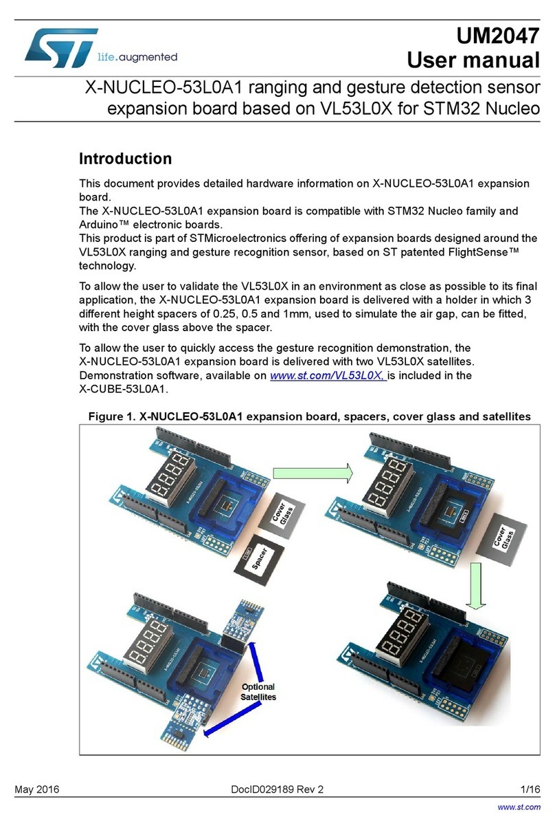
STMicroelectronics X-NUCLEO-53L0A1 User manual
STMicroelectronics
STMicroelectronics ST8034C User manual
STMicroelectronics
STMicroelectronics X-NUCLEO-IHM08M1 User manual
STMicroelectronics
STMicroelectronics STEVAL-C34KAT1 User manual
STMicroelectronics
STMicroelectronics RM0365 User manual
STMicroelectronics
STMicroelectronics B-G474E-DPOW1 User manual
STMicroelectronics
STMicroelectronics STM32Cube User manual
STMicroelectronics
STMicroelectronics X-NUCLEO-53L1A2 User manual


