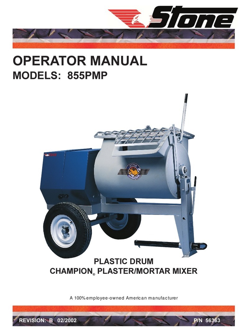
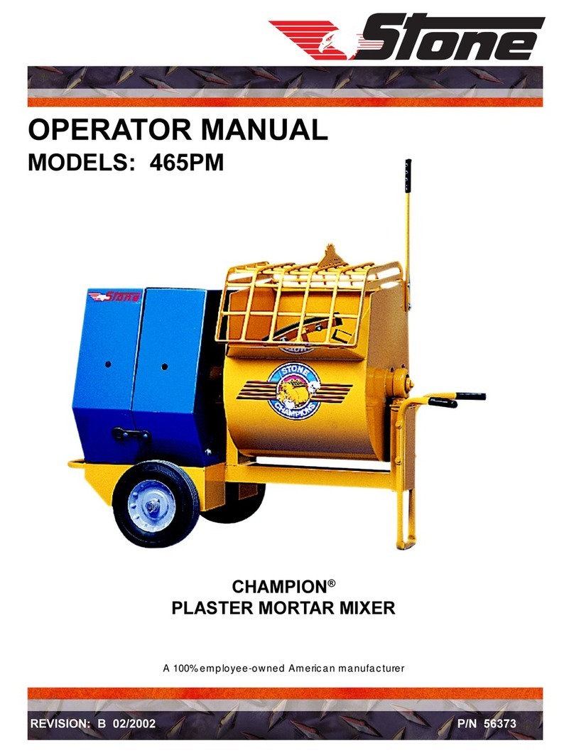
Stone Champion 655PMP Building instructions

SERVICE/PARTS MANUAL
MODELS: 655PMP & 855PMP
PLASTIC DRUM
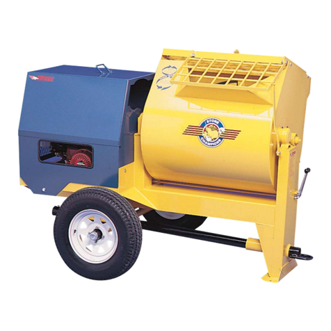
CHAMPION® PLASTER/MORTAR MIXER
A 100% employee-owned American manufacturer
REVISION: A 02/2003 P/N 56558


- 3 -
TABLE of CONTENTS
FOREWORD ................................................................................................................................... 4
LIMITED WARRANTY ................................................................................................................. 5
TECHNICAL DATA ....................................................................................................................... 6 -9
Specifications .............................................................................................................................. 6
Machine Sound & Vibration Measurements ................................................................................ 7
Imperial Torque Chart .................................................................................................................
Metric Torque Chart .................................................................................................................... 9
HEALTH & SAFETY ..................................................................................................................... 10 - 15
OPERATION ................................................................................................................................... 16
Location and Use of Controls ...................................................................................................... 16
MAINTENANCE ............................................................................................................................ 17 - 24
Cleaning ...................................................................................................................................... 17
Lubrication .................................................................................................................................. 17
Hardware ..................................................................................................................................... 17
Towing ......................................................................................................................................... 1
Bull Gear Assembly ..................................................................................................................... 1
Electric Wiring ............................................................................................................................ 19-20
Maintenance Schedule ................................................................................................................. 21
Maintenance Chart ...................................................................................................................... 22
Bearing & Seal Installation Instructions...................................................................................... 23
HARDWARE IDENTIFICATION ................................................................................................ 24
EXPLODED DIAGRAM AND PARTS LIST .............................................................................. 25 - 49
Frame and Drum Assembly ......................................................................................................... 26-29
Paddle Assembly/Blade and Paddle Sets ..................................................................................... 30-31
Clutch Lever Assembly................................................................................................................ 32-33
Electric Motor Drive Train .......................................................................................................... 34-37
Gas Engine Drive Train ............................................................................................................... 3 -41
Optional Spring Axle Assembly .................................................................................................. 42-43
Standard Axle Assembly .............................................................................................................. 44-45
Trailer Lights Assembly Option .................................................................................................. 46-47
Decal Identification ..................................................................................................................... 4 -49
CALIFORNIA PROPOSITION 65 WARNING ........................................................................... I C
MANUFACTURED UNDER ONE OR MORE OF THE FOLLOWING PATENTS AND OTHERS
PENDING: 3761058, 3905519, 3931748, 3932006, 4043540, 4180281.
655PMP, 855PMP

- 4 -
User Information
These instructions include:
Safety regulations
Operating instructions
Maintenance instructions
These instructions have been prepared for
operation on the construction site and for the
maintenance engineer.
These instructions are intended to simplify
operation of the machine and to avoid
malfunctions through improper operation.
Observing the maintenance instructions will
increase the reliability and service life of the
machine when used on the construction site
and reduce repair costs and downtimes.
Always keep these instructions at the place of
use of the machine.
Only operate the machine as instructed and
follow these instructions.
Observe the safety regulations as well as the
guidelines of the civil engineering trade
association. Observe the safety rules for
operation and the pertinent regulations for the
prevention of accidents.
Stone Construction Equipment, Inc. is not liable
for the function of the machine when used in
an improper manner or for other than the
intended purpose.
Operating errors, improper maintenance and
the use of incorrect operating materials are not
covered by the warranty.
The above information does not extend the
warranty and liability conditions of business of
Stone Construction Equipment, Inc.
P.O. Box 150, Honeoye, New Yor 14471
Phone: (800) 888-9926
Fax: (585) 229-2363
Foreword
1. Machine Type: ______________________________
Machine S/N: _______________________________
2. Engine Type: _______________________________
Engine S/N: ________________________________
3. VIN: ______________________________________
4. Purchase Date: ______________________________
. Dealer/Distributor Information:
Name: _____________________________________
Address: ___________________________________
__________________________________________
Phone #: ___________________________________
Fax #: _____________________________________
6. Battery
Manufacturer: ______________________________
Battery Type: _______________________________
Battery S/N: ________________________________
Location of above information:
1. Information on S/N tag.
2. Information on engine tag.
3. Information on S/N tag - if applicable.
4. Date you purchased machine.
. Dealer machine was purchased from.
6. Information on battery and battery warranty card.

- 5 -
L i m i t e d W a r r a n t y
The Manufacturer warrants that products manufactured shall be free from defects in material and
workmanship that develop under normal use for a period of 90 days for concrete vibrators and electric
pumps, one year for Rhino®, Bulldog®, WolfPac Rollers, trowels, Stompers®, saws, forward plates,
engine powered pumps, Lift Jockey, Mortar Buggyand 6 months for all other products from the date
of shipment. The foregoing shall be the exclusive remedy of the buyer and the exclusive liability of the
Manufacturer. Our warranty excludes normal replaceable wear items, i.e. gaskets, wear plates, seals, O-
rings, V-belts, drive chains, clutches, etc. Any equipment, part or product which is furnished by the
Manufacturer but manufactured by another, bears only the warranty given by such other manufacturer.
(The Manufacturer extends the warranty period to “Lifetime” for the drum bearings and seals for the mortar
mixers, and agrees to furnish, free of charge, the bearings and seals only upon receipt of the defective
parts. The warranty is two years for eccentric bearings on the forward plate compactors, mortar and plaster
mixer drums, trowel gearboxes and five years on the Bulldog trench roller eccentric bearings.) A Warranty
Evaluation Form must accompany all defective parts. Warranty is voided by product abuse, alterations,
and use of equipment in applications for which it was not intended, use of non-manufacturer parts, or failure
to follow documented service instructions. The foregoing warranty is exclusive of all other warranties
whether written or oral, expressed or implied. No warranty of merchantability or fitness for a particular
purpose shall apply. The agents, dealer and employees of Manufacturer are not authorized to make
modification to this warranty, or additional warranties binding on Manufacturer. Therefore, additional
statements, whether oral or written, do not constitute warranty and should not be relied upon.
The Manufacturer’s sole responsibility for any breach of the foregoing provision of this contract, with respect
to any product or part not conforming to the Warranty or the description herein contained, is at its option (a)
to repair, replace or refund such product or parts upon the prepaid return thereof to location designated
specifically by the Manufacturer. Product returns not shipped prepaid or on an economical transportation
basis will be refused (b) as an alternative to the foregoing modes of settlement - the Manufacturer’s dealer
to repair defective units with reimbursement for expenses, except labor, and be reviewed with the
Manufacturer prior to repair. A Warranty Evaluation Form must accompany all warranty claims.
Except as set forth hereinabove and without limitation of the above, there are no warranties or other
affirmations which extends beyond the description of the products and the fact hereof, or as to operational
efficiency, product reliability or maintainability or compatibility with products furnished by others. In no
event whether as a result of breach of contract or warranty or alleged negligence, shall the Manufacturer be
liable for special or consequential damages including but not limited to: Loss of profits or revenues, loss of
use of the product or any associated product, cost of capital, cost of substitute products, facilities or services
or claims of customers.
No claim will be allowed for products lost or damaged in transit. Such claims should be filed with the carrier
within fifteen days.
Effective July 2002.
P/N 51018 F-7080 7/2002
Stone Construction Equipment, Inc. • 8662 Main Street, P. O. Box 150 • Honeoye, NY 14471-0150
Phone: 1-800-888-9926 • 1-585-229-5141 Fax: 1-585-229-2363


- 6 -
TECHNICAL DATA Specifications
MODEL
Origin
Dimensions
Operating Wt. lbs/Kg
Batch Capacity (Bags)
Batch Capacity cu. t. / cu. m.
Total Volume cu. t. / cu. m.
L x W x H in. / cm
Operating System
Engine
Drive & Clutch
Standard Features
Drum
Drum Lock in. / mm
Paddles:
Number
Mixing Action
Paddle Sha t
Frame/Axle:
Tow Pole
Axle - extendible
Tires
Cowl:
Other Features:
Bag Splitter
Sa ety Guard
Guard Li ter
Sa ety Chain
Warranty:
Warranty Machine
Warranty Drum Bearing
Drum Warranty
Options:
655PMP
U.S.A.
550 ./ 250
1 1/2 - 2 bags
6 / .17
6.9 / .20
64 x 34 x 54 / 163 x 86 x 137
5 hp B&S / 3.7 kw
5.5 hp Hon a / 4.10 kw
6 hp Robin / 4.5 kw
8 hp B&S / 6.0 kw
8 hp B&S I/P / 6.0 kw
8.5 hp Robin / 6.3 kw
8 hp B&S / 6.0 kw
8 hp Hon a / 6.0 kw
1 1/2 hp / 1.1 kw Electric
V-Belt to Gears
Front Post Han Clutch
polyetheline
automatic (patente )
4
Simple figure 8
1 1/2" / 38.1 mm roun
Post Gussett, pintle,
pin or ball hitch
34" - 46" / 86 - 117 cm
4.8 x 12 (high spee )
16 galv., stainless steel hinge,
iamon shape expan e
steel vent panels
stan ar
lift away, heavy- uty
stan ar (patente )
stan ar
6 months
lifetime on patente
qua ruple bearings an seals
2 years
light option
855PMP
U.S.A.
605 / 275
2 1/2 - 3 bags
8 / .23
9.0 / .25
76 x 34 x 54 / 193 x 86 x 137
8 hp B&S / 6.0 kw
8 hp B&S I/P / 6.0 kw
8.5 hp Robin / 6.3 kw
8 hp B&S / 6.0 kw
8 hp Hon a / 6.0 kw
10 hp B&S I/C / 7.5 kw
2 hp / 1.5 kw Electric
3 hp / 2.2 kw Electric
V-Belt to Gears
Front Post Han Clutch
polyetheline
automatic (patente )
4
Simple figure 8
1 1/2" / 38.1 mm roun
Post Gussett, pintle,
pin or ball hitch
34" - 46" / 86 - 117 cm
B78 x 13 (high spee )
16 galv., stainless steel hinge,
iamon shape expan e
steel vent. panels
stan ar
lift away, heavy- uty
stan ar (patente )
stan ar
6 months
lifetime on patente
qua ruple bearings an seals
2 years
spring axle
light option

- 7 -
TECHNICAL DATA Machine Sound &
Vibration Measurements
Sound Pressure Values as measured are per the following:
Noise 1 Model/Configuration
Sound Pressure 855PMP
8hp Honda
Tow pole end 92dBA
Cowl end right side (exhaust) 98dBA
Cowl end back of unit 98dBA
Cowl end left side 94dBA
Sound Pressure measurements were taken with Simpson model 886-2 type 2 meter,
calibrated 2/21/97
Acceleration measurements were taken with Quest Tech model VI-100 meter, calibrated
4/17/96
Sound and vibration measurements obtained with machine operating at maximum.
Test date was 7/29/98 with test conditions at 23 degrees Celsius
\\mktg\stone1\netaldus\pm5\engr\bonnie\bln\sound_pm.doc

- -
TECHNICAL DATA Imperial Torque Chart
SAE GRADE 8
Coarse Thread
SIZE PLATED
1/4 –20 (.250) 9 ft. lbs. 12 Nm
5/16 –18 (.3125) 18 ft. lbs. 24 Nm
3/8 –16 (.375) 33 ft. lbs. 45 Nm
7/16 –14 (.4375) 52 ft. lbs. 70 Nm
1/2 –13 (.500) 80 ft. lbs. 108 Nm
9/16 –12 (.5625) 115 ft. lbs. 156 Nm
5/8 –11 (.625) 159 ft. lbs. 215 Nm
3/4 –10 (.750) 282 ft. lbs. 382 Nm
7/8 –9 (.875) 454 ft. lbs. 615 Nm
1 –8 (1.000) 682 ft. lbs. 925 Nm
SAE GRADE 8
Fine Thread
SIZE PLATED
1/4 –28 (.250) 10 ft. lbs. 14Nm
5/16 –24 (.3125) 20 ft. lbs. 27 Nm
3/8 –24 (.375) 37 ft. lbs. 50 Nm
7/16 –20 (.4375) 58 ft. lbs. 79 Nm
1/2 –20 (.500) 90 ft. lbs. 122 Nm
9/16 –18 (.5625) 129 ft. lbs. 175 Nm
5/8 –18 (.625) 180 ft. lbs. 244 Nm
3/4 –16 (.750) 315 ft. lbs. 427 Nm
7/8 –9 (.875) 501 ft. lbs. 679 Nm
1 –12 (1.000) 746 ft. lbs. 1011 Nm
1 –14 (1.000) 764 ft. lbs. 1036 Nm
SAE GRADE 5
Coarse Thread
SIZE PLATED
1/4 –20 (.250) 6 ft. lbs. 8 Nm
5/16 –18 (.3125) 13 ft. lbs. 18 Nm
3/8 –16 (.375) 23 ft. lbs. 31 Nm
7/16 –14 (.4375) 37 ft. lbs. 50 Nm
1/2 –13 (.500) 57 ft. lbs. 77 Nm
9/16 –12 (.5625) 82 ft. lbs. 111 Nm
5/8 –11 (.625) 112 ft. lbs. 152 Nm
3/4 –10 (.750) 200 ft. lbs. 271 Nm
7/8 –9 (.875) 322 ft. lbs. 436.5 Nm
1 –8 (1.000) 483 ft. lbs. 655 Nm
SAE GRADE 5
Fine Thread
SIZE PLATED
1/4 –28 (.250) 7 ft. lbs. 10Nm
5/16 –24 (.3125) 14 ft. lbs. 19 Nm
3/8 –24 (.375) 26 ft. lbs. 35 Nm
7/16 –20 (.4375) 41 ft. lbs. 56 Nm
1/2 –20 (.500) 64 ft. lbs. 87 Nm
9/16 –18 (.5625) 91 ft. lbs. 123 Nm
5/8 –18 (.625) 128 ft. lbs. 173 Nm
3/4 –16 (.750) 223 ft. lbs. 302 Nm
7/8 –14 (.875) 355 ft. lbs. 481 Nm
1 –12 (1.000) 529 ft. lbs. 717 Nm
1 –14 (1.000) 541 ft. lbs. 733 Nm

- 9 -
TECHNICAL DATA Metric Torque Chart
3URSHUW\&ODVV
=,1&3/$7('
&RDUVH7KUHDG )LQH7KUHDG
6,=( 1P IWOEV 1P IWOEV
0
0
0
0
0
0
0
0
3URSHUW\&ODVV
=,1&3/$7('
&RDUVH7KUHDG )LQH7KUHDG
6,=( 1P IWOEV 1P IWOEV
0
0
0
0
0
0
0
0
3URSHUW\&ODVV
=,1&3/$7('
&RDUVH7KUHDG )LQH7KUHDG
6,=( 1P IWOEV 1P IWOEV
0
0
0
0
0
0
0
0
&RQYHUVLRQ)DFWRUIWOE 1

- 10 -
HEALTH & SAFETY Safety Precautions
SAFETY
These machines are designed to carry out the function of
mixing material of the non-cohesive, bituminous and granu-
lar varieties.
If used correctly, they will provide an effective and safe
means of mixing and meet the appropriate performance
standards.
It is essential that the operator of the machine is adequately
trained in its safe operation, be authorized to operate it,
and have sufficient knowledge of the machine to ensure
that it is in full working order, before being put to use.

- 11 -
HEALTH & SAFETY Safety Precautions
Before using this equipment, study this entire manual to
become familiar with its operation. Do not allow
untrained or unauthorized personnel, especially children,
to operate this equipment. Use only factory authorized
parts for service.
When warning decals are destroyed or missing, contact
the Manufacturer immediately at 1- 00- -9926 for
replacement. For the safety of yourself and others, it is
imperative that the following rules are observed. Failure
to do so may result in serious injury or death.
This notation appears before warnings in the text. It means that the
step which follows must be carried out to avoid the possibility of
personal injury or death. These warnings are intended to help the
technician avoid any potential hazards encountered in the normal
service procedures. We strongly recommend that the reader takes
advantage of the information provided to prevent personal injury or
injury to others.
FOLLOW SAFETY INSTRUCTIONS
Carefully read all safety messages and decals in this manual and on
your machine safety signs. Keep decals in good condition. Replace
missing or damaged decals. Be sure new equipment components and
repair parts include the current safety signs. Replacement safety signs
and decals are available through your dealer.
Learn how to operate the machine and how to use controls properly.
Do not let anyone operate without instruction.
Keep your machine in proper working condition. Unauthorized
modifications to the machine may impair the function and/or safety
and affect machine life.
If you do not understand any part of this manual and need assistance,
contact your dealer.
UNDERSTAND SIGNAL WORDS
A signal word DANGER, WARNING, or CAUTION is used with
the safety-alert symbol. DANGER identifies the most serious hazards.
DANGER or WARNING safety signs are located near specific
hazards. General precautions are listed on CAUTION safety signs.
CAUTION also calls attention to safety messages in this manual.

- 12 -
HEALTH & SAFETY Safety Precautions
HOT SURFACES
Avoid contact with hot exhaust systems and engines.
Allow all components in the engine compartment to cool before
performing any service work.
USE COMMON SENSE WHEN HANDLING FUELS
Transport and handle fuel only when contained in approved safety
container.
Do not smoke when refueling or during any other fuel handling
operation.
Do not refuel while the engine is running or while it is still hot.
If fuel is spilled during refueling, wipe it off from the engine
immediately and discard the rag in a safe place.
Do not operate the equipment if fuel or oil leaks exist - repair
immediately.
Never operate this equipment in an explosive atmosphere.
Always use the proper size grounded extension cord, forming to
the National Electric Code and Local Ordinances.
Inspect all extensions and electrical cords for cuts, frayed wire and
broken connectors before use. Do not use cords if not in good
condition.
Do not route extension cords through standing water.
Do not operate the mixer in standing water.
When cleaning the mixer, never spray water over the motor.
Never leave mixer unattended while running.
Mix only Motor, Plaster, Terrazzo, Fireproofing and Grout.
Do Not operate machine if rocks, stones, ice or frozen materials are
in mix and/or in drum of mixer. The machine could jam, causing
damage to the equipment or injury to the operator.
WARNING

- 13 -
HEALTH & SAFETY Safety Precautions
PREPARE FOR EMERGENCIES
Be prepared if a fire starts.
Keep a first aid kit and fire extinguisher handy.
Keep emergency numbers for doctors, ambulance service, hospital,
and fire department near your telephone.
Never perform any work on the mixer while it is running.
Before working on the mixer, stop the engine and disconnect the
spark plug wire(s) to prevent accidental starting. On electric models,
disconnect the electric cord at the mixer.
Keep cowl closed during the operation, close cowl immediately after
starting.
Keep hands, clothing and jewelry away from all moving parts.
Keep all guards in place, including drum guards.
Never stick your hands or any solid object into the drum while the
mixer is in operation.
WEAR PROTECTIVE CLOTHING
Wear close fitting clothing and safety equipment appropriate to the
job.
Prolonged exposure to loud noise can cause impairment or loss of
hearing.
Wear a suitable hearing protective device such as earmuffs or
earplugs to protect against objectionable or uncomfortable loud
noises.
Operating equipment safely requires the full attention of the
operator. Do not wear radio or music headphones while operating
machine.

- 14 -
HEALTH & SAFETY Safety Precautions
Starting fluid (ether) is highly flammable, do not use or an
explosion or fire may result.
Never operate unit in a poorly ventilated or enclosed area.
Avoid prolonged breathing of exhaust gases.
Engine exhaust fumes can cause sickness or death.
Warning-Towing
•Warning: Do not tow the mixer with the drum in the dump position.
Mixer may become unstable and tip over when hitting a curb,
pothole, or other obstruction.
•Warning: Always properly attach safety chains before mixer is
towed. Maximum towing speed 55 m.p.h. (90 km/hr). Reduce
speed according to highway conditions.
Warning-Eye Protection
•Always wear splash goggles when operating mixer.

- 15 -
HEALTH & SAFETY Safety Precautions
PRACTICE SAFE MAINTENANCE
Understand service procedure before doing work. Keep area clean
and dry.
Never lubricate, service or adjust machine while it is moving. Keep
hands, feet, and clothing from power-driven parts. Disengage all
power and operate controls to relieve pressure. Lower equipment to
the ground. Stop the engine. Remove the key. Allow machine to
cool.
Securely support any machine elements that must be raised for
service work.
Keep all parts in good condition and properly installed. Fix damage
immediately. Replace worn or broken parts. Remove any buildup of
grease, oil, or debris.
Disconnect battery ground cable (-) before making adjustments on
electrical systems or welding on machine.
DISPOSE OF WASTE PROPERLY
Improperly disposing of waste can threaten the environment and
ecology. Potentially harmful waste used with equipment include
such items as oil, fuel, coolant, brake fluid, filters, and batteries.
Use leakproof containers when draining fluids. Do not use food or
beverage containers that may mislead someone into drinking from
them.
Do not pour waste onto the ground, down a drain, or into any water
source.
Air conditioning refrigerants escaping into the air can damage the
Earths atmosphere. Government regulations may require a certified
air conditioning service center to recover and recycle used air
conditioning refrigerants.
Inquire on the proper way to recycle or dispose of waste from your
local environmental or recycling center.
SAFETY DECALS - FOR THE SAFETY OF YOURSELF AND OTHERS REPLACE ANY
DAMAGED OR MISSING SAFETY DECALS.
Warning Decal (SN-91) P/N 55010
Warning Decal (SN-92) P/N 55011
Safety Instruction Decal (SN-67A) P/N 55013
Warning Decal (SN- ) P/N 55014
Safety Chain Decal (Front Post, SN-66) P/N 55121

- 16 -
OPERATION Location and Use of Controls
Before operating this unit, it is important to
familiarize yourself, and any other personnel
who will be using it, with the location and
proper use of the controls to insure safe and
efficient operation.
A. Always make sure that the drum latch
is in the lock position (down) before
starting machine. With engine running,
turn clutch le er to the rightto turn
paddles or to the left to stop.
B. To dump mix from drum, stop paddles,
mo e drum latch up and pull dump
handle down. Always use caution
when dumping mix.
C. Always grease drum seals (at both
ends) as recommended in the
maintenance chart. The grease purges
dirt, prolonging bearing life.
D. Always keep drum and paddles clean.
Ne er run machine with hardened mix
or foreign objects in drum. Doing so
damages paddles and/or engine.

- 17 -
MAINTENANCE
CLEANING
FAILURE TO FOLLOW CLEANING
INSTRUCTION AND/OR ROTATION OF
DRUM WITHOUT GUARD LIFTER
CONNECTED CAN RESULT IN SERIOUS
INJURY.
For consistent performance, long life and continued
high quality mixing of plaster or mortar, thoroughly
clean the mixer inside and out at the end of each day's
operation. To prevent lumps of dried plaster from
forming and contaminating future batches of plaster
or mortar, do not allow build up materials to form on
drum guards, around paddles or anywhere inside the
drum.
Before cleaning, shut the engine or motor and
disconnect the spark plug wire or electric cord to
prevent accidental starting.
Keep drum guard closed.
Always keep guard lifter connected.
Keep drum in upright, mixing position.
Spray mixer with water before mix dries to remove
accumulation.
Rotate drum to dump position to remove debris.
DO NOT beat on the drum with a shovel, hammer or
other device to break up accumulations of dried mix, as
this will dent and damage the drum.
WARNING
NEVER POUR OR SPRAY WATER OVER THE
ENGINE OR MOTOR.
NEVER PUT HANDS OR ANY O JECT INTO
THE DRUM WHILE THE ENGINE OR
MOTOR IS RUNNING.
ALWAYS DISCONNECT THE SPARK PLUG
WIRE OR ELECTRIC CORD WHEN
CLEANING INSIDE DRUM.
ALWAYS MAKE SURE GUARD LIFTER IS
RECONNECTED TO GUARD EFORE USING
MIXER, DO NOT OPERATE THE MIXER
WITH DRUM GUARD OPEN OR
REMOVED.WHEEL EARING
LU RICATION
Fill wheel hub with grease to inside diameter of outer
races and also fill hub grease cap. Never use grease
heavier than 265 A.S.T.M. penetration (No. 2 grade).
Grease bearing cone by machine or by hand method.
Force grease between rollers, cone and cage. (If Ball
Bearing Hub: force grease between balls.) It is not
recommended that a pressure grease fitting be
installed on the hub.
HARDWARE
Periodically inspect all hardware on the mixer and
engine / motor. Loose hardware can contribute to
early component failure and poor performance.
NOTE: Some hardware is used to retain parts that
have to move freely for correct operation of this unit.
These items include the guard lifter and drum guard.
The hardware for these items should be snug enough
to prevent excessive play, yet loose enough to allow
the parts to pivot freely.
Cleaning/Lubrication/Hardware
WARNING

- 1 -
MAINTENANCE
WARNING
TOWING
Before attempting to tow this mixer, check the state
and local laws that apply to your intended route and
check the following:
1.Hitch attached to the towing vehicle securely.
2.Towpole fully extended and bolted to mixer
securely.
3.Safety chain hooked up properly (see illustration
below or decal on mixer front post).
4. Drum in the mixing position and drum latch
engaged, clutch lever in the UP position.
5. Lug nuts and axle mount nuts tight.
6. On extendible axles, axle extended to full width
and adjustment bolts tight.
7. On spring axles--splring mounting hardware
tight, main springs and snubber springs not
cracked or broken.
. Tires in good shape and at proper infation, for
maximum safety and load capacity tires should
be inflacted to the followintg pressures.
Tire size 4. 0 x 12 @ 60 P.S.I.
Tire size 6.50 x 13 @ 32 P.S.I.
DO NOT EXCEED A TOWING SPEED OF 55
MILES/HR (90 KM/HR). FOR POOR ROAD
CONDITIONS OR INCLEMENT WEATHER,
REDUCE SPEED ACCORDINGLY.
Refer to FRAME AND DRUM ASSEMBLY,
STANDARD AXLE ASSEMBLY and SPRING
AXLE ASSEMBLY sections of this manual for parts
identification and location.
ULL GEAR ASSEM LY
1. Align Bull Gear keyway opposite to gear
mesh.
2. Adjust pinion for tooth alignment and
engagement using .010 feeler gauge.
3. Tighten all four (4) pillow block bolts before
removing feeler gauge.
Towing/Bull Gear Assy

- 19 -
MAINTENANCE Electric Wiring

- 20 -
MAINTENANCE Electric Wiring
This manual suits for next models
1
Table of contents
Other Stone Construction Equipment manuals

Stone
Stone 95CMP User manual

Stone
Stone WolfPac 3100 User manual

Stone
Stone CHAMPION 465PM User manual

Stone
Stone RP522 User manual

Stone
Stone WolfPac 2500 User manual

Stone
Stone Rhino 43 Series User manual

Stone
Stone TR24 User manual

Stone
Stone HM1290 User manual

Stone
Stone WolfPac 6100 User manual

Stone
Stone TR24 User manual