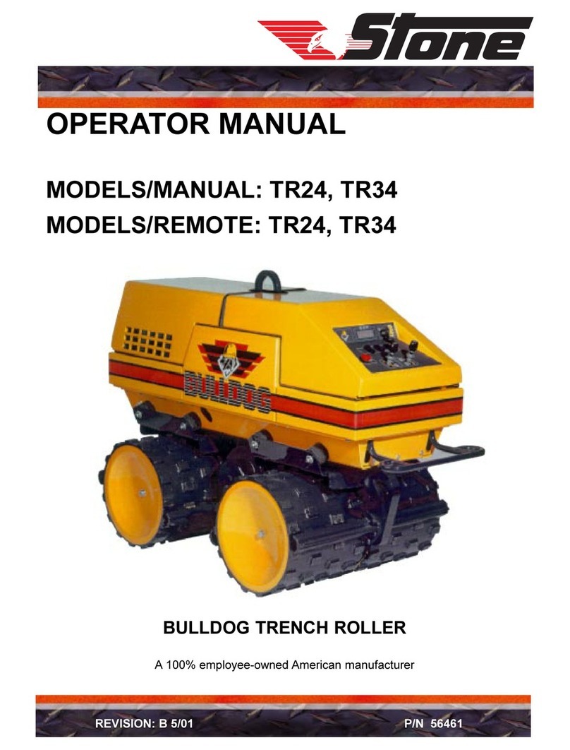
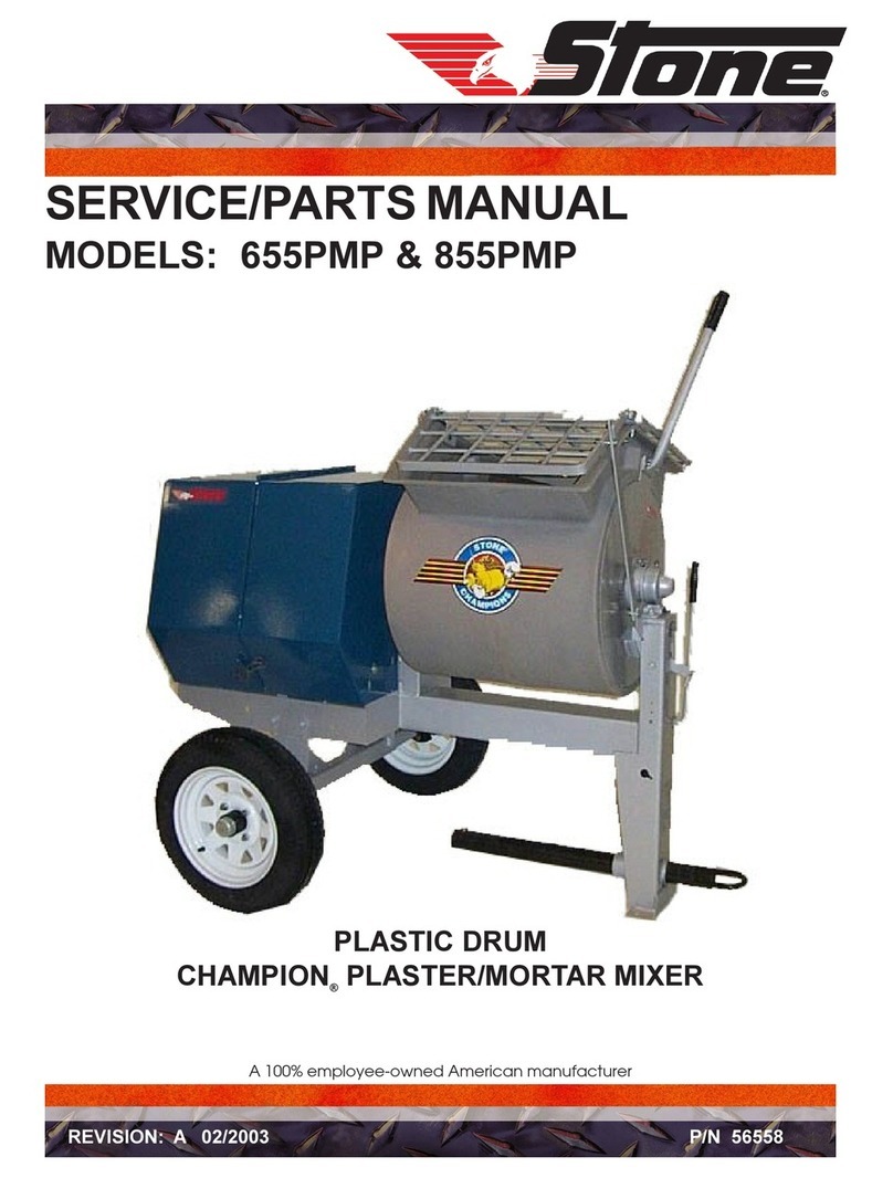
Stone TR24 User manual

OPERATOR MANUAL
MODELS/MANUAL: TR24, TR34
MODELS/REMOTE: TR24, TR34
BULLDOG®TRENCH ROLLER
A 100% employee-owned American manufacturer
REVISION: A 2/2004 P/N 56637


FOREWORD ................................................................................................................................... 6
WARRANTY .................................................................................................................................... 7
SECTION 1 - TECHNICAL DATA ............................................................................................... 9 - 13
1.1 Machine Specifications .................................................................................................. 10
1.2 Engine Specifications ..................................................................................................... 11
1.3 Lubrication Specifications .............................................................................................. 11
1.4 Machine Sound Level Test ............................................................................................. 11
1.5 Manual Operator Controls ............................................................................................. 12
1.6 Remote Operator Controls ............................................................................................. 13
SECTION 2 - HEALTH & SAFETY ............................................................................................. 15 - 22
SECTION 3 - OPERATION ........................................................................................................... 23 - 29
3.1 Introduction .................................................................................................................... 24
3.2 Machine Configuration Description ............................................................................... 24
3.2.1 Manual Operation Only ............................................................................... 24
3.2.2 Manual/Remote Operation .......................................................................... 24 - 25
3.3 Before Starting ............................................................................................................... 25
3.3.1 Warnings ...................................................................................................... 25
3.3.2 Pre-Start Checklist....................................................................................... 25
3.4 Starting The Machine ..................................................................................................... 25
3.4.1 Manual Mode .............................................................................................. 25
3.4.2 Activating The Remote Control System ...................................................... 25
3.4.3 Remote Mode .............................................................................................. 25 - 26
3.5 Shutting The Machine Off .............................................................................................. 26
3.5.1 Manual Mode .............................................................................................. 26
3.5.2 Remote Mode .............................................................................................. 26
3.6 Emergency Stop .............................................................................................................. 26
3.7 Parking The Machine ..................................................................................................... 26
3.7.1 Parking Brake .............................................................................................. 27
3.8 Engine Speed/Throttle Control ....................................................................................... 27
3.8.1 Manual Mode .............................................................................................. 27
3.8.2 Remote Mode .............................................................................................. 27
3.9 Machine Vehicle Speed ................................................................................................... 27
3.9.1 Manual Mode .............................................................................................. 27
3.9.2 Remote Mode .............................................................................................. 27
TABLE of CONTENTS Bulldog®

3.10 Direction And Steering Control ...................................................................................... 27
3.10.1 Manual Mode .............................................................................................. 27 - 28
3.10.2 Remote Mode .............................................................................................. 28
3.11 Vibration Control ...........................................................................................................28
3.11.1 Manual Mode .............................................................................................. 28
3.11.2 Remote Mode .............................................................................................. 28
3.12 Safety Anti-Crush Bar .................................................................................................... 28
3.12.1 Purpose And Location ................................................................................. 28
3.12.2 Operation ..................................................................................................... 28
3.12.3 Inspection .................................................................................................... 28 - 29
3.13 Operation On Scopes ...................................................................................................... 29
SECTION 4 - LED DISPLAY ......................................................................................................... 31 - 33
4.1 Location And Operation ................................................................................................. 32
4.2 Display During Start-Up - Voltage ................................................................................. 32
4.3 Display During Run - RPM ........................................................................................... 32
4.4 Hour Meter ..................................................................................................................... 32
4.5 Fault Messages ...............................................................................................................32
4.6 Fault Storage .................................................................................................................. 32 - 33
4.7 Warnings .....................................................................................................................33
SECTION 5 - RADIO SET ............................................................................................................. 35 - 37
5.1 Operating Principle ........................................................................................................ 36
5.2 Identification Numbers ................................................................................................... 36
5.3 Components .................................................................................................................... 36
5.4 Operating Instructions .................................................................................................... 36
5.5 Power ..................................................................................................................... 36
5.6 Diagnostics ..................................................................................................................... 37
5.7 Radio Set Care ...............................................................................................................37
SECTION 6 - MAINTENANCE..................................................................................................... 39 - 50
6.1 Important ..................................................................................................................... 40
6.2 Periodic Maintenance ..................................................................................................... 41
6.3 Fuel Filter / Water Separator .......................................................................................... 42
6.4 Fuel Tank ..................................................................................................................... 42
6.5 Fuel Lines ..................................................................................................................... 42
6.6 Engine Oil and Filter ...................................................................................................... 42
6.7 Air Cleaner ..................................................................................................................... 42
6.8 Cooling System .............................................................................................................. 42
TABLE of CONTENTS Bulldog®

TABLE of CONTENTS Bulldog®
6.9 Valve Clearance ..............................................................................................................42
6.10 Hydraulic Oil .................................................................................................................. 43
6.11 Hydraulic Oil Filter ........................................................................................................43
6.12 Hydraulic Breather Cap ................................................................................................. 43
6.13 Eccentric ..................................................................................................................... 43 - 44
6.14 Eccentric Housing Oil .................................................................................................... 44
6.15 Engine Mounting ............................................................................................................ 44
6.16 Hardware ..................................................................................................................... 44
6.17 Loctite ..................................................................................................................... 44
6.18 Fuel Injectors .................................................................................................................. 44
6.19 Transmitter Batteries ...................................................................................................... 44
6.20 ECIB (Brick) .................................................................................................................. 44
6.21 Fuse Replacement ........................................................................................................... 44 - 45
6.22 Battery Policy ................................................................................................................. 45
6.23 Servicing Battery ............................................................................................................ 45
6.24 Removing / Installing Battery ......................................................................................... 45
6.25 Jump Starting ................................................................................................................. 45 - 46
6.26 Storage .....................................................................................................................46
6.27 Spring Start-Up .............................................................................................................. 46
6.28 Troubleshooting .............................................................................................................. 47 - 49
6.29 Service Record ............................................................................................................... 50
CALIFORNIA PROPOSITION 65 WARNING ........................................................................... 55

- 6 -
Warranty Information
Please enter the following data. This will help
expedite any service or warranty work.
1. Machine Type: _______________________
Machine S/N: ________________________
2. Engine Type: _________________________
Engine S/N: __________________________
3. VIN: _______________________________
4. Purchase Date: _______________________
5. Dealer/Distributor Information:
Name: ______________________________
Address: ____________________________
____________________________________
Phone #: ____________________________
Fax #: ______________________________
Location of above information:
1. Information on S/N tag.
2. Information on engine tag.
3. Information on S/N tag - if applicable.
4. Date you purchased machine.
5. Dealer machine was purchased from.
These instructions include:
Safety regulations
Operating instructions
Maintenance instructions
These instructions have been prepared for
operation on the construction site and for the
maintenance engineer.
These instructions are intended to simplify operation
of the machine and to avoid malfunctions through
improper operation.
Observing the maintenance instructions will increase
the reliability and service life of the machine when
used on the construction site and reduce repair costs
and downtimes.
Always keep these instructions at the place of use
of the machine.
Only operate the machine as instructed and follow
these instructions.
Observe the safety regulations as well as the
guidelines of the civil engineering trade
association. Observe the safety rules for the
operation of road rollers and compactors and the
pertinent regulations for the prevention of
accidents.
Stone Construction Equipment, Inc. is not liable for
the function of the machine when used in an
improper manner or for other than the intended
purpose.
Operating errors, improper maintenance and the use
of incorrect operating materials are not covered by
the warranty.
The above information does not extend the warranty
and liability conditions of business of Stone
Construction Equipment, Inc.
Stone Construction Equipment, Inc.
P.O. Box 150, Honeoye, New York 14471
Phone: (800) 888-9926
Fax: (585) 229-2363
FOREWORD

- 7 -
L i m i t e d W a r r a n t y
The Manufacturer warrants that products manufactured shall be free from defects in material and
workmanship that develop under normal use for a period of 90 days for concrete vibrators and electric
pumps, one year for Rhino®, Bulldog®, WolfPac Rollers™, trowels, Stompers®, saws, forward plates, engine
powered pumps, Lift Jockey™, Mortar Buggy™and 6 months for all other products from the date of
shipment. The foregoing shall be the exclusive remedy of the buyer and the exclusive liability of the
Manufacturer. Our warranty excludes normal replaceable wear items, i.e. gaskets, wear plates, seals, O-
rings, V-belts, drive chains, clutches, etc. Any equipment, part or product which is furnished by the
Manufacturer but manufactured by another, bears only the warranty given by such other manufacturer.
(The Manufacturer extends the warranty period to “Lifetime” for the drum bearings and seals for the mortar
mixers, and agrees to furnish, free of charge, the bearings and seals only upon receipt of the defective
parts.The warranty is two years for eccentric bearings on the forward plate compactors, mortar and plaster
mixer drums, trowel gearboxes, three years on the Bulldog trench roller microprocessor (ECIB) and five
years on the Bulldog trench roller eccentric bearings.) A Warranty Evaluation Form must accompany all
defective parts. Warranty is voided by product abuse, alterations, and use of equipment in applications for
which it was not intended, use of non-manufacturer parts, or failure to follow documented service instructions.
The foregoing warranty is exclusive of all other warranties whether written or oral, expressed or implied.
No warranty of merchantability or fitness for a particular purpose shall apply. The agents, dealer and
employees of Manufacturer are not authorized to make modification to this warranty, or additional warranties
binding on Manufacturer. Therefore, additional statements, whether oral or written, do not constitute warranty
and should not be relied upon.
The Manufacturer’s sole responsibility for any breach of the foregoing provision of this contract, with respect
to any product or part not conforming to the Warranty or the description herein contained, is at its option (a)
to repair, replace or refund such product or parts upon the prepaid return thereof to location designated
specifically by the Manufacturer. Product returns not shipped prepaid or on an economical transportation
basis will be refused (b) as an alternative to the foregoing modes of settlement - the Manufacturer’s dealer
to repair defective units with reimbursement for expenses, except labor, and be reviewed with the
Manufacturer prior to repair. A Warranty Evaluation Form must accompany all warranty claims.
Except as set forth hereinabove and without limitation of the above, there are no warranties or other
affirmations which extends beyond the description of the products and the fact hereof, or as to operational
efficiency, product reliability or maintainability or compatibility with products furnished by others. In no
event whether as a result of breach of contract or warranty or alleged negligence, shall the Manufacturer be
liable for special or consequential damages including but not limited to: Loss of profits or revenues, loss of
use of the product or any associated product, cost of capital, cost of substitute products, facilities or services
or claims of customers.
No claim will be allowed for products lost or damaged in transit. Such claims should be filed with the carrier
within fifteen days.
Effective January 2004.
P/N 51018 G-7524 01/2004
Stone Construction Equipment, Inc. • 8662 Main Street, P. O. Box 150 • Honeoye, NY 14471-0150
Phone: 1-800-888-9926 • 1-585-229-5141 Fax: 1-585-229-2363


- 9 -
1. TECHNICAL DATA

- 10 -
1. TECHNICAL DATA Bulldog®
Model Type TR24 TR34
Operating Weight lbs (kg) 2,900 lbs (1318 kg) 3,100 lbs (1406 kg)
L x W x H in (cm) 66 x 24 x 46.4 in
(167.7 x 61 x 119 cm)
66 x 34 x 46.4 in
(167.7 x 86 x 118 cm)
Drum Diameter in (cm) 19.7 in (50 cm) 19.7 in (50 cm)
Drum Width in (cm) 24 in (61 cm) 34 in (86.4 cm)
Engine hp (kw) 20 hp Hatz (15 kw) 20 hp Hatz (15 kw)
Operating Speed RPM (Hz) Up to 2,800 RPM (46.6 Hz) Up to 2,800 RPM (46.6 Hz)
Driving & Steering Hydrostatic Hydrostatic
Hydraulic Reservoir gal (l) 13 gal (49 l) 13 gal (49 l)
Fuel Tank Capacity gal (l) 3 gal (11.5 l) 3 gal (11.5 l)
Vib Frequency vpm (Hz) 2,000 vpm (33.3 Hz) 2,000 vpm (33.3 Hz)
Centrifugal Force lbs (kN) 15,709 lbs (69.87 kN) 15,709 lbs (69.87 kN)
Total Applied Force lbs (kN) 18,609 lbs (82.7 kN) 18,809 lbs (83.7 kN)
Static Linear Pressure PSI (N/cm) 60.4 PSI (105 N/cm) 48 PSI (85 N/cm)
Dynamic Linear Pressure PSI (N/cm) 327 PSI (572 N/cm) 247 PSI (432 N/cm)
Total Applied Linear Pressure PSI (N/cm) 387.7 PSI (677 N/cm) 295 PSI (516 N/cm)
Static Padfoot Pressure PSI (N/cm) 136.8 PSI (94.34 N/cm) 73.06 PSI (516 N/cm)
Dynamic Padfoot Pressure PSI (N/cm) 740 PSI (510 N/cm) 370 PSI (127.85 N/cm)
Total Applied Padfoot Pressure PSI (N/cm) 876.8 PSI (604.7 N/cm) 443.30 PSI (647.5 N/cm)
Gradeability: With Vib On
With Vib Off
45%
55%
45%
55%
Travel Speed: Hi Without Vib
Ft/min (m/min) Low With Vib
136 ft/min (41.5 m/min)
68 ft/min (20.7 m/min)
136 ft/min (41.5 m/min)
68 ft/min (20.7 m/min)
Maximum Lift in (cm) 27 in
(68.6 cm)
27 in
(68.6 cm)
Tip Angle 42°43°
Productivity sq ft/hr (sq m/hr) 8,160 sq ft/hr (758 sq m/hr) 10,798.47 sq ft/hr
(1,003.5 sq m/hr)
Standard Features Include: internal and external drum scrapers, drum covers, lift eye, dry element air filter, hydraulic
oil sight gauge, electric start, zero-turning radius, zero edge clearance, Snap-TekTM electronic connection system.
Optional Features: Snap-TekTM radio-frequency remote control kit, test port gauge kit.
1.1 - Stone Bulldog®– Specifications

- 11 -
1. TECHNICAL DATA Machine Data & Machine Sound Level Values
1.4 MACHINE SOUND LEVEL TEST
Machine Type: Bulldog T rench Compaction Roller
Sound Level Meter Calibration Date: February 15, 2000
Meter Type: Simpson Model 886-2 Type 2
T est Date: February 15, 2000
Te s t C on d i ti on s
T emperat ure: 3 1 degrees Fahrenheit / -1 degree Celsius
Ambient Sound: dba fast mode
Soil Condition: Silts and clays
Moisture Limit: Approximately equal to 50%
Engine speed: 2800 rpm / 46.6 Hz
Frequency: 2000 vpm / 33.3 Hz
Test Site; Honeoye, New York USA
Sound Level at Operat or P osit ion: 90 dba wit hout vibe
93 dba wit h vibe
1.3 LUBRICATION SPECIFICATIONS
Type Quantity
Engine Crankcase SAE 15W40
API-CD, CE Super Diesel
(See Hatz instruction book for
proper viscosity that matches
the ambient temperature)
Approximately 2 quarts
(1.9 liters)
Hydraulic System Mobil 424 SUS255
55CST ISO VG55
13 gallons (49 liters)
Eccentric Oil SAE 30W 16 ounces (473 milliliters)
1.2 ENGINE S PEC IFICATIO NS
Engine Type 2-cylinder, 4-cycle, air-cooled, diesel
Engine Make Hatz
Engine Model 2G40
Power @ 3000 RPM 20 HP (15 kW)
Operating Speed 2800 RPM
A lt e rn at or 1 2 Vo lt 15 Am p
Battery 12 Volt System Battery BCI Group 34
Air Cleaner 2-stage centrifugal - Donaldson
Fuel Filt er W at er separator type - Hatz
Fuel T ype No. 2 diesel fuel
Fuel T ank Capacity 3 gallons (11.5 liters)
Fuel Consumption .375 lbs./HPh @ 2850 RPM

- 12 -
1. TECHNICAL DATA
1.5 MANUAL OPERATOR CONTROLS
1. Keyswitch - Keyswitch positions noted above.
2. E-Stop Button - Emergency stop.
3. Led Display - Message display/hour meter.
4. Vibe Direction Button - Vibration shaft direction.
5. Vibe On/Hi Speed Button - Vibration on, high travel speed or low travel speed.
6. Engine Throttle Button - Idle speed (turtle) or run speed (rabbit).
7. Right Side Forward/Reverse Control - Controls drum operation on the right side.
8. Left Side Forward/Reverse Control - Controls drum operation on the left side.
9. Radio Remote On/Off Switch.
Accessory
Position
OFF
Position
RUN
Position
Engine Start
Position
1
6
7
5
8
2
9
4
3

- 13 -
1. TECHNICAL DATA
1.6 REMOTE OPERATOR CONTROLS
1. Green Link/Start Button - Starts machine/engine.
2. Red Battery Light - Indicates low batteries in transmitter.
3. Left Side Forward Button - Controls drum operation.
4. Left Side Reverse Button - Controls drum operation.
5. Low Travel Speed Button - Also shuts off vibe function.
6. Vibe Reverse Button - Turns vibe on and controls direction.
7. No Function.
8. Red E-Stop/Power Off Button - Stops machine/engine.
9. Yellow Active Light - Flashes when linked to receiver.
10. Right Side Forward Button - Controls drum operation.
11. Right Side Reverse Button - Controls drum operation.
12. High Travel Speed Button - Also shuts off vibe function.
13. Vibe Forward Button - Turns vibe on and controls direction.
14. No function.
1
2
3
4
5
6
7
8
9
10
11
12
13
14


- 15 -
2. HEALTH & SAFETY

- 16 -
SAFETY USE
These machines are designed to carry out the function
of compacting material of the cohesive, bituminous and
granular varieties.
If used correctly they will provide an effective and safe
means of compaction and meet the appropriate
performance standards.
It is essential that the driver/operator of the machine is
adequately trained in its safe operation, be authorized to
drive it, and have sufficient knowledge of the machine
to ensure that it is in full working order before being put
to use.

- 17 -
2. HEALTH & SAFETY Safety Precautions
Before using this equipment, study this entire manual to
become familiar with its operation. Do not allow untrained
or unauthorized personnel, especially children, to operate
this equipment. Use only factory authorized parts for
service.
When warning decals are destroyed or missing, contact
the Manufacturer immediately at 1-800-888-9926 for
replacement. For the safety of yourself and others, it is
imperative that the following rules are observed. Failure
to do so may result in serious injury or death.
SAFETY PRECAUTIONS
•This notation appears before warnings in the text. It means that
the step which follows must be carried out to avoid the possibility
of personal injury or death. These warnings are intended to help
the technician avoid any potential hazards encountered in the
normal service procedures. We strongly recommend that the
reader takes advantage of the information provided to prevent
personal injury or injury to others.
FOLLOW SAFETY INSTRUCTIONS
•Carefully read all safety messages and decals in this manual and
on your machine safety signs. Keep decals in good condition.
Replace missing or damaged decals. Be sure new equipment
components and repair parts include the current safety signs.
Replacement safety signs and decals are available through your
dealer.
•Learn how to operate the machine and how to use controls
properly. Do not let anyone operate without instruction.
•Keep your machine in proper working condition. Unauthorized
modifications to the machine may impair the function and/or
safety and affect machine life.
•If you do not understand any part of this manual and need
assistance, contact your dealer.
UNDERSTAND SIGNAL WORDS
•A signal word –DANGER, WARNING, or CAUTION –is used
with the safety-alert symbol. DANGER identifies the most
serious hazards.
•DANGER or WARNING safety signs are located near specific
hazards.
•General precautions are listed on CAUTION safety signs.
CAUTION also calls attention to safety messages in this manual.

- 18 -
2. HEALTH & SAFETY Safety Precautions
•Never operate unit in a poorly ventilated or enclosed area.
•Avoid prolonged breathing of exhaust gases.
USE COMMON SENSE WHEN HANDLING FUELS
•Transport and handle fuel only when contained in approved safety
container.
•Do not smoke when refueling or during any other fuel handling
operation.
•Do not refuel while the engine is running or while it is still hot.
•If fuel is spilled during refueling, wipe it off from the engine
immediately and discard the rag in a safe place.
•Do not operate the equipment if fuel or oil leaks exist - repair
immediately.
•Never operate this equipment in an explosive atmosphere.
•EXPLOSION WARNING! Cigarettes, flames, or sparks could cause
battery to explode. Always shield eyes and face from battery. Do
not charge or use booster cables or adjust post connections without
proper instruction and training. KEEP VENT CAPS TIGHT AND
LEVEL.
•POISON WARNING! Battery contains sulfuric acid. Avoid
contact with skin, eyes, and clothing. In event of an accident, flush
with water and call a physician immediately. KEEP OUT OF THE
REACH OF CHILDREN.
•Ear protection required when operating this equipment.
•Qualified personnel only. No untrained operators. Serious injury may
occur.
•Users must be trained to operator this roller. Read the Operator’s
Manual. Learn to operate this roller safely.
•Do not operate across the sides of hills, roller may tip over.
•Do not operate at the edge of trenches or roads, roller may tip over.

- 19 -
2. HEALTH & SAFETY Safety Precautions
HOT SURFACES
•Avoid contact with hot exhaust systems and engines.
•Allow all components in the engine compartment to cool before
performing any service work.
•Hydraulic system produces high pressures - incorrect hose
replacement can cause serious personal injury. When performing
service, refer to Service/Parts Manual for hose identification and
connections.
•Caution: Escaping hydraulic fluid under pressure can have sufficient
force to penetrate the skin, causing serious personal injury.
•Hydraulic fluid escaping under pressure from a very small hole can
be almost invisible. Use a piece of cardboard or wood to search for
possible leaks.
•Never use your hands to detect pressure leaks.
•Hydraulic tank temperature can reach 180 degrees F maximum.
•Never perform any work on the roller while it is running. Before
working on the roller, stop the engine and remove the ignition key to
prevent accidental starting, block drums to prevent rolling.
•Keep engine cover closed during the operation.
•Keep hands, clothing, and jewelry away from all moving parts.
•Keep all guards in place.
•Keep feet clear of all drums.
•Keep work area free of bystanders
•For foot protection, wear steel toe shoes or toe pads.
•Pressurized release of fluids from the hydraulic system can cause
serious burns.
•Shut off engine. Only remove filler cap when cool enough to touch
with bare hands. Slowly loosen cap to first stop to relieve pressure
before removing completely.

- 20 -
2. HEALTH & SAFETY Safety Precautions
PRACTICE SAFE MAINTENANCE
•Understand service procedure before doing work. Keep area clean
and dry.
•Never lubricate, service or adjust machine while it is moving.
Keep hands, feet, and clothing from power-driven parts. Disengage
all power and operate controls to relieve pressure. Lower
equipment to the ground. Stop the engine. Remove the key. Allow
machine to cool.
•Securely support any machine elements that must be raised for
service work.
•Keep all parts in good condition and properly installed. Fix
damage immediately. Replace worn or broken parts. Remove any
buildup of grease, oil, or debris.
•Disconnect battery ground cable (-) before making adjustments on
electrical systems or welding on machine.
PREPARE FOR EMERGENCIES
•Be prepared if a fire starts.
•Keep a first aid kit and fire extinguisher handy.
•Keep emergency numbers for doctors, ambulance service,
hospital, and fire department near your telephone.
WEAR PROTECTIVE CLOTHING
•Wear close fitting clothing and safety equipment appropriate to
the job.
•Prolonged exposure to loud noise can cause impairment or loss of
hearing.
•Wear a suitable hearing protective device such as earmuffs or
earplugs to protect against objectionable or uncomfortable loud
noises.
•Operating equipment safely requires the full attention of the
operator. Do not wear radio or music headphones while
operating machine.
Other manuals for TR24
1
This manual suits for next models
1
Table of contents
Other Stone Construction Equipment manuals

Stone
Stone TR24 User manual

Stone
Stone WolfPac 2500 User manual

Stone
Stone HM1290 User manual

Stone
Stone Mud Buggy SB1600 Guide

Stone
Stone Rhino 43 Series User manual

Stone
Stone 95CMP User manual

Stone
Stone CHAMPION 855PMP User manual

Stone
Stone WolfPac 3100 User manual

Stone
Stone Champion 655PMP Building instructions

Stone
Stone WolfPac 3100 Guide