Stoneridge SE5000 Use and maintenance manual

Stoneridge - Setting the standard
www.SE5000.com
SE5000 Digital Tachograph
Ready to
drive
Control Manual


Important
Important
The Stoneridge tachograph SE5000 Rev 7.4 has full
type approval for use in the European union accord-
ing with Commission Regulation (EC) No.
1360/2002 of 13 June 2002 and other related leg-
islatives.
The Approval Certificate number is e5-0002. This
number will be indicated on all Stoneridge tacho-
graph.
The tachograph fulfils the requirements of UNECE
regulation number 10, revision 03, approval No
03XXX, in respect of electromagnetic compatibility.
Contact Stoneridge
You are welcome to forward any queries or sug-
gestions you may have about the Tachograph and
the operating instructions to any of our sales offices,
as listed below.
United Kingdom
Stoneridge Electronics Ltd
Charles Bowman Avenue
Claverhouse Industrial Park
Dundee, Scotland
UK
Phone: +44 (0)1382 866 400
Fax: +44 (0)1382 866 401
E-mail: amsales@stoneridge.com
France
Stoneridge Electronics France
Z.I St. Etienne
F-64100 Bayonne
France
Phone: +33 (0)5 59 50 80 40
Fax: +33 (0)5 59 50 80 41
E-mail: france.amsales@stoneridge.com
Germany
IVEKA Automotive Technologies
Schauz GmbH
Talweg 8
D-75417 Mühlacker-Lomersheim
Germany
Phone: +49 (0)7041 9695-0
Fax: +49 (0)7041 9695-55
E-mail: info@iveka.de
Italy
Stoneridge Electronics s.r.l.
Viale Caduti nella Guerra di Liberazione, 568
00128 Rome
Italy
Phone: +39 06 50 86 10 01
Fax: +39 06 50 86 10 06
E-mail: italy.amsales@stoneridge.com
Netherlands
C.A.S.U. - Utrecht b.v.
Ravenswade 118
NL-3439 LD Nieuwegein
Netherlands
Phone: +31 (0)30 288 44 70
Fax: +31 (0)30 289 87 92
E-mail: info@casuutrecht.nl
Spain
Stoneridge Electronics España
Avda. Severo Ochoa 38
Pol. Ind. Casa Blanca
28108 Alcobendas
Madrid
Spain
Phone: +34 91 662 32 22
Fax: +34 91 662 32 26
E-mail: spain.amsales@stoneridge.com
Sweden
Stoneridge Nordic AB
Gårdsfogdevägen 18 A
SE-168 66 Stockholm
Sweden
Phone: +46 (0)8 154400
Fax: +46 (0)8 154403
E-mail: info@stoneridgenordic.se
Tachograph Version
Digital Tachograph SE5000 Rev 7.4.
Internet Information
Further information about Stoneridge Digital Tacho-
graph SE5000 and about Stoneridge Electronics Ltd
can be found at:
www.se5000.com
www.stoneridgeelectronics.info
Copyright
This manual must not be reprinted, translated, or
otherwise reproduced in whole or in part, without
written permission from Stoneridge Electronics AB.
- 1 -

Important
Blank Page
- 2 -

Table of Contents
Table of Contents
Important 1
Contact Stoneridge 1
United Kingdom 1
France 1
Germany 1
Italy 1
Netherlands 1
Spain 1
Sweden 1
Tachograph Version 1
Internet Information 1
Copyright 1
Blank Page 2
Table of Contents 3
Blank Page 4
Introduction 5
The Control Card 5
Don't open the Case 5
Blank Page 6
Overview 7
Encrypted Motion Sensor (1) 7
Digital Tachograph (2) 7
Display in Instrument Cluster (3) 7
Control and Driver Card (4) 7
Blank Page 8
User Interface 9
Blank Page 10
Downloading Data 11
General 11
Download Equipment 11
Control Card 11
Inserting a Control Card 11
Eject a Control Card 11
Storing Data 11
Storing Data on the Control Card 11
Storing Control Activities in the Tachograph 12
Downloading Data 12
System Inspection 13
General 13
Visual Check 13
Inspection Procedure 13
Installation Plaque 13
Checking Second Source Motion Sensor 14
Pictograms 15
Symbols 15
Symbol Combinations 15
Blank Page 16
Printouts 17
Printout Examples 17
18
Technical Data 18
Events and Faults (VU) 19
Details of Events and Faults (VU) 20
Events and Faults (card) 20
Daily Printout (card) 21
Daily Printout (card) continued 21
Daily Printout (VU) 22
Daily Printout (VU) continued 22
Overspeeding 23
Blank Page 24
Display Messages 25
- 3 -

Table of Contents
Blank Page
- 4 -

Introduction
Introduction
This manual concerns the control mode of oper-
ation. However, knowledge of the operational mode
of the unit is also required in case of driving a tacho-
graph fitted vehicle.
A Stoneridge tachograph can be operated in one of
four modes of operation:
lOperational (driver card or no card inserted)
lControl (control card inserted)
lCalibration (workshop card inserted)
lCompany (company card inserted)
Company Lock-in/Lock-out details can be used to
identify the true owners of blocks of stored tacho-
graph data. Enforcement officers should encourage
companies to Lock-in tachograph data as it not only
identifies their company as the owner of the data,
but also prevents third party company card owners
from viewing or downloading their data.
Also, when transferring ownership of a tachograph
to another company, the current tachograph owner
must Lock-out the data before transfer of the tacho-
graph. Thus any future data stored after the Lock-
out would be clearly identified as not applying to
them.
Due to data protection laws, care must be taken to
ensure that the tachograph data is not downloaded
and passed on to third parties without the per-
mission of the tachograph owner.
The control card can be inserted in either of the
trays. If control cards are inserted in both trays the
card in tray 1 will be used for the control operation
and the card in tray 2 will be ignored.
The Control Card
lMust be obtained via an application to the relevant
authorities.
lIs valid for 2 years only.
lWill only be issued to enforcement officers or
enforcement authorities.
lAre personal to the enforcement officer and
authority and is not transferable.
lAllows read-only access to data stored in the driver
card or in the tachographs internal memory respec-
tively.
lCan store a minimum of 230 records of displaying
and/or printing and/or VU downloading and/or
card downloading. The maximum number of rec-
ords is dependent on the card type. When the
upper limit is reached the oldest data will be over-
written.
Note!
Extra care must be taken to ensure that only the
authorised owner of a control card has access to
it at all times.
Don't open the Case
The tachograph has been installed by authorised per-
sonnel.
A tachograph case must never be opened. No tam-
pering with or modifications to the tachograph sys-
tem are permitted. A tamper label is placed inside the
printer housing. The tamper label must not be torn
apart.
Here you can see where the tampering label is placed
and how it looks when it is untouched.
A tampered label might look like this.
Note!
Unauthorized persons that modify this equipment
are committing a punishable offence, depending
on the legislation in the country concerned.
- 5 -

Introduction
Blank Page
- 6 -

Overview
Overview
The Tachograph installation.
1
2
4
3
1. Encrypted motion sensor
2. Digital tachograph, with integrated display and
printer
3. Display in vehicle’s instrument cluster
4. Card
Encrypted Motion Sensor (1)
Used to provide the tachograph with speed signal
pulses from the vehicle gearbox. To ensure the integ-
rity of the speed sensor signal, the speed signal is
transferred between the sensor and the tachograph
in an encrypted form. Encrypting the speed signal
ensures that any tampering with the signal will be
detected and recorded.
Digital Tachograph (2)
The tachograph records and stores various data:
lWorkshop or driver card data.
lWarnings and malfunctions relating to tachograph,
driver, company and workshop.
lVehicle information, odometer data and detailed
speed.
lTampering the tachograph. For more information
on the tachograph, see the Driver & Company
Manual.
Display in Instrument Cluster (3)
The display in the instrument cluster can be used to
display information passed from the tachograph,
such as speed (speedometer) and distance travelled
(trip and odometer).
Control and Driver Card (4)
The following cards dedicated for specific usage can
be used in the tachograph:
lDriver card - records the drivers activities.
lControl card - authority control and inspection.
lWorkshop card - calibration mode.
lCompany card - hauliers and vehicle owners, down
loading and storage of data.
Note!
All cards are personal and may not be used by
anyone else but the rightful card holder.
- 7 -

Overview
Blank Page
- 8 -

User Interface
User Interface
The tachograph detailed within this manual com-
prises two card tray mechanisms, a printer, an LCD
display, a calibration/download interface (6-pin con-
nector located behind paper cassette) and user con-
trols, located in an ISO standard radio enclosure.
This type of enclosure enables mounting in a variety
of locations, ensuring that insertion and removal of
the driver cards and operation of the controls can be
easily achieved by an operator.
The tachograph complies with EU Regulations and
displays and records speed and distance in metric
units (kilometres per hour and kilometres respec-
tively).
The tachograph also incorporates an internal clock,
which is used to indicate the current time on the
tachograph display. The tachograph is available for
use in both 12 and 24 V vehicle systems.
1
78
345 6
00h30
05h48
00h00
16:30
1. Display
2. Printer, 6-pin calibration/download connector,
behind the paper cassette
3. Driver card tray
4. Cancel button
5. Up button
6. Down button
7. Enter button
8. Driver button
9. Co-driver button
10. Co-driver card tray
- 9 -

User Interface
Blank Page
- 10 -

Downloading Data
Downloading Data
General
An enforcement officer can download data from a
digital tachograph system. Downloading means the
copying, together with a security digital signature, of
a partial or a complete set of data that is stored in the
memory of a tachograph or on a driver card.
The download must be done to aid investigations
into “Drivers Hours” legislation checks and to aid
determination of the validity of the digital tacho-
graph systems. When carrying out “Drivers Hours”
investigations, care must be taken to identify the true
owners of blocks of stored tachograph data.
Dedicated download equipment or a valid control
card is essential for the downloading of the data
stored in the tachograph or on the driver card.
Download Equipment
Behind the paper cassette is a 6-pin connector
located. This is where the required downloading
equipment is connected.
Control Card
A valid control card is required to download or to
view driving data stored on either an inserted driver
card or in the tachographs data memory. The control
card provides read-access to the entire tachograph
data memory contents whether or not the data has
been company locked using a valid company card.
Inserting a Control Card
Insert the control card in either of the trays (No. 1 in
our example).
1. Press and hold button 1on the tachograph until
the tray is opened.
2. Insert the card with the chip facing forward and
upwards.
3. Close the tray by pushing it carefully forward.
The control card must be inserted to identify the
controller/user.
4. Close the tray by pushing it in carefully. The
tachograph now processes the control card data.
If the control card authentication fails, see heading
Display Messages on page 25.
The card tray is locked when the vehicle is in
motion, while the tachograph is busy processing the
control card and if the power supply to the tacho-
graph is interrupted.
Eject a Control Card
1. Press button 1or 2on the tachograph and hold it
until the tray opens.
2. Press the card up slightly from underneath
through the opening on the tray, or push the
edge of the tray down until the card pops out.
3. Close the tray by pushing it carefully forward.
Note!
Withdrawal of the Control Card is not possible in
all menus.
Storing Data
When a control card is inserted into a tachograph in
order to perform a control activity, a record of the
control activity is stored on the control card and in
the tachograph as described below. The type of con-
trols that can be performed are displaying, down-
loading or printing data from the tachograph and/or
the card.
Storing Data on the Control Card
On the control card a single record will be stored.
This record contains the following:
lThe card number.
lThe issuing Member state, issuing authority name
and the issue date.
lThe card validity date.
lThe control body name and address.
lThe surname and forename of the card holder.
lThe preferred language.
Each time a control card is used to carry out a con-
trol activity the following data is stored on the con-
trol card:
lThe date and time of the control activity.
lThe type of control activity performed.
lThe period downloaded, if applicable.
lThe VRN (Vehicle Registration Number) and
Member State registering authority of the con-
trolled vehicle.
lThe card number and card issuing Member State,
in case of controlling a card.
- 11 -

Downloading Data
Storing Control Activities in the
Tachograph
Each time a control card is used to carry out a con-
trol activity a record of the activity is stored in the
tachograph. The data in each record is:
lDate and time of the control.
lThe control card number and card issuing Member
State.
lThe type of control.
Note!
In case of downloading, the date of the oldest
and most recent days downloaded must also be
recorded.
Downloading Data
To download data do the following:
1. Remove the paper cassette.
2. Attach the download equipment to the tacho-
graph through the 6-way front download con-
nector.
3. Start downloading data according to the instruc-
tion on the download equipment.
When the download is completed, the following
message will be displayed.
Download complete
If the download process has failed and is incomplete
the following message will be displayed:
Download failed
If the download fails:
4. Remove the control card.
5. Check the connections.
6. Check the download equipment.
7. Re-insert the control card and redo the process
until downloading is made.
If the data download cannot be completed and the
following message is displayed:
Download fault
The tachograph is found to be the cause or if it is
unsure whether the card or the tachograph is faulty,
the vehicle must be taken to a Tachograph Work-
shop for investigation.
- 12 -

System Inspection
System Inspection
General
The control function involves a number of different
functions associated with the digital tachograph sys-
tem. A tachograph inspection is done to ensure that
it still meets the EU legislation requirements.
For example, downloading and checking the data
stored on either the driver card or in the tachograph
internal memory, and an inspection of the tacho-
graph system.
Note!
If any unit fails the inspection the vehicle must be
taken to a Workshop for further investigation.
Visual Check
1. Ensure that there is no damage to or drill-holes in
the entire exterior casing including underneath
rubber acorn, which would imply a tampering
attempt.
2. Check for evidence of tampering with the seals
and labels.
3. Check for additional seals and labels that do not
belong to the tachograph, as they might cover
drill-holes. There should be only one label on the
tachograph.
4. Check that the heat seals is present.
5. Check the tachograph type approval mark.
6. Check that the predetermined breakpoints are
unbroken.
1
1. Predetermined breakpoint.
7. Check that all tachograph system seals are intact.
8. Confirm the presence of the installation plaque.
9. Check that the label and Stoneridge logotype hol-
ogram is present and in one piece. The position
of the label is shown in the illustration below.
Two different seals are used.
Inspection Procedure
Follow this procedure to confirm that the function
of the recording equipment is correct:
1. Check that the operation of the recording equip-
ment including data storage on cards is sat-
isfactory.
2. Determine that the tachograph operates within
maximum tolerances for both speed and dis-
tance.
3. Compare that the actual circumference and tyre
size corresponds with the information on the
installation plaque.
4. Check the internally stored calibration factors
according to the installation plaque with a tech-
nical printout.
5. Check the internally stored vehicle parameters,
VIN (Vehicle Identification Number) and VRN
(Vehicle Registration Number) and compare to
the actual vehicle data with a technical printout
6. Check the correctness of the UTC time.
Note!
If the UTC time is inaccurate by more than 20 min-
utes, the vehicle must be taken to a workshop for
recalibration.
Installation Plaque
The final part of the digital tachograph system instal-
lation procedure is the completion and fitment of an
installation plaque.
The installation plaque must be clearly visible and
easily accessible. The installation plaque is normally
placed on the recording equipment, the vehicle's "B"
pillar or the doorframe on the driver's side of the
vehicle.
The installation plaque state the following:
lConstant of the tachograph, K factor (imp/km).
lEffective circumference of the wheel tyres, L fac-
tor (mm).
- 13 -

System Inspection
lCharacteristic coefficient of the vehicle, W factor
(imp/km).
lTyre size.
lVehicle Identification Number (VIN).
lName, address or trade name of the approved fitter
or workshop.
lDate of calibration.
Checking Second Source Motion
Sensor
If the tachograph system is required to have a sec-
ond motion sensor this section describes how this
shall be checked. Checking can be carried out by
viewing the Motion Sensor View.
With the control card inserted, press the arrow down
button several times until you reach the last view,
which is the Motion Sensor View. See position (3)
below to check if a second source motion sensor is
present.
Note!
If second source of motion function is disabled
this view will not be shown.
34
2
1
1 045Km/h
2 050Km/h 27
1. Primary Motion Sensor speed.
2. Indicates motion. If this pictogram is shown ( - ),
no motion is detected.
3. Second source of motion speed. The digits
shows the speed indication of the second
source.
If these characters (- - -) are shown instead of
the digits, the tachograph does not receive sig-
nals from a second source motion sensor.
4. Fault number.
- 14 -

Pictograms
Pictograms
Symbols
This is a list of the most frequently shown symbols
on the display and on the printouts.
Symbol Description
Function not available
Driver or slot
Co-driver or slot
Card
Eject
Work
Driving/driver (mode of Operation)
Rest/break
Available
Ferry / train crossing
OUT Out of scope, -i.e. no recording is
required
Local time/location
Start of daily work period
End of daily work period
Break
From or to
Printer, printout
Paper
Display
Processing, please wait
Time, clock
UTC UTC time
24h Daily
|Weekly
|| Two weeks
Total/summary
Speed
Over speeding
Faults
!Events
?Pre-warning/question/unknown activity
Workshop
Company
Controller
Manufacturer
Security
External storage/download
Buttons
Finished
Tachograph (VU), vehicle
Tyre size
Sensor
Power supply
Print
Print, submenu
Company lock
Places
Places, sub menu
Settings
Symbol Combinations
The following combination of symbols are the most
common.
Symbols Description
Location start of daily work period
Location end of daily work period
From time (UTC)
To time (UTC)
Local time
Crew driving
Driving time for two weeks
OUT
Out of scope - begin
OUT
Out of scope - end
Cumulative driving time of current day
Printer low temperature
Printer high temperature
No card
Driver card
Workshop card
Company card
Control card
Control place
From vehicle
- 15 -

Pictograms
Blank Page
- 16 -

Printouts
Printouts
The information stored on the tachograph and on the driver cards can be printed. There are a number of dif-
ferent printouts available, see below.
1. Press OK to show the menu and select:
PRINT
1. Press OK and select the type of printout to make. Then press OK.
Some types of printouts require specification of the driver card and a date. If so the following is displayed:
Select card 1 or 2
2. Select 1to make a printout for the current driver's card or 2to make a printout for a co-driver's card. The fol-
lowing is displayed:
Select date
3. Select the desired date by using the arrow buttons and press OK.
4. Now you select whether to view the data on the display only or to make a printout on paper.
lTo view the data on the display only, select:
display
lPress OK and scroll through the data using the arrow buttons and then press OK to return.
lTo make a printout on paper, select
printer
lPress OK. The display will show:
Printer busy
lIf you would like to cancel the process, press and hold the Back button. Wait until the message is cleared
and then pull the printout upwards to tear it off.
Note!
To avoid paper jam make sure the slot on the paper cassette is not blocked.
Printout Examples
On the following pages there are a number of printout examples that can be selected from the PRINTmenu:
lDaily printout (card) 24h card (including local time).
lEvent and faults (card) event card.
lEvent and faults (VU) event vu.
lDrive Time Info drive time info
lTechnical data technical data.
lOverspeeding overspeeding.
lVehicle speed vehicle speed.
lEngine speed (rpm) engine speed.
lStatus D1/D2 status D1/D2.
lManual Entry Sheet man entry sheet.
- 17 -

Printouts
Technical Data
This printout list data as speed settings, tyre
size, calibration data and time of adjust-
ments.
The display shows the following (on the sec-
ond line):
technical data
12
4
3
6
1
5
2
8
10
7
9
11
Stoneridge Electronics
Adolfsbergsvägen 3
S70227 örebro
900208E7.3/01R01
ABCD1E2345678910
19/10/2010 08:41 (UTC)
NL /AA-BB-12
SVN31309
1234567890/7878/06/A2
1234567890/1006/07/A1
2010
vP477 31/07/2010
Stoneridge
Andersson
Richard
S /00007001106910 0 0
23/05/2015
14
13 e1-175
05/08/2010
22
20
24
26
23
21
19
18
17
16
15
25
27
w
k
l
29
30
28
ABCD1E2345678910
NL /AA-BB-12
S /12345678901012 1 0
Johansson and Sons
123 45 BROMMA
31/08/2016
06/08/2010 (2)
9 150 Imp/km
9 150 Imp/km
3 331 mm
w
k
l315/80R22.5
89 km/h
0 km; 26 km
15 km; 15 km
S /12345678901012 1 0
31/08/2016
05/08/2010 (1)
?????????????
9 150 Imp/km
9 150 Imp/km
3 331 mm
315/80 R22.5
89 km/h
STONERIDGE ELECTRONICS
168 66 BROMMA
NL /AA-BB-12
33
34
32
31
S /12345678901012 1 0
19/10/2010 08:40
19/10/2010 08:40
!!x
x
06/08/2010 10:40
06/08/2010 10:41
!
Johansson and Sons
123 45 BROMMA
1. Date and time.
2. Type of printout (technical data).
3. Cardholder ID.
4. Vehicle Identification Number (VIN).
5. Vehicle Registration Number (VRN) and country of
registration.
6. Tachograph manufacturer.
7. Tachograph part number.
8. Tachograph approval number.
9. Tachograph serial number, date of manufacture,
type of equipment and code of manufacturer.
10. Year of manufacture.
11. Software version and installation date.
12. Motion sensor serial number.
13. Motion sensor approval number.
14. Date of first installation of motion sensor.
15. Workshop having performed the calibration.
16. Workshop address.
17. Workshop card identification.
18. Workshop card expiry date.
19. Calibration date and purpose.
20. VIN
21. VRN and country of registration.
22. Characteristic coefficient of vehicle.
23. Constant of the recording equipment.
24. Effective circumference of wheel tyres.
25. Vehicle tyre size.
26. Authorized speed setting.
27. Old and new odometer values.
28. Calibration date and purpose.
29. VIN.
30. VRN and country of registration.
31. Old date and time (Before time adjustment).
32. New date and time (After time). adjustment
33. Most recent event time.
34. Most recent fault date time.
- 18 -
Other manuals for SE5000
8
Table of contents
Other Stoneridge Automobile Accessories manuals

Stoneridge
Stoneridge ORLACO Sets MirrorEye MP User guide
Stoneridge
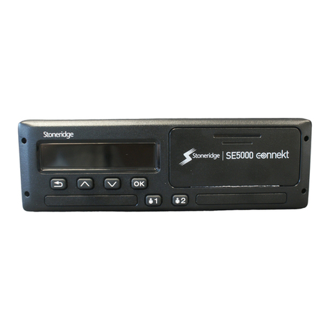
Stoneridge SE5000-8 RG User manual
Stoneridge
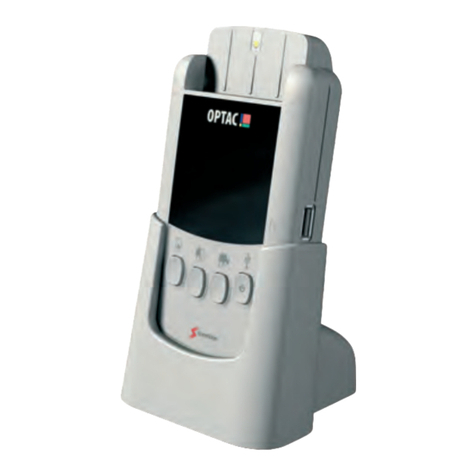
Stoneridge Optac 3 User manual
Stoneridge
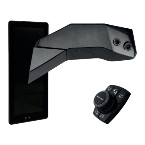
Stoneridge MirrorEye 0416100 User guide
Stoneridge
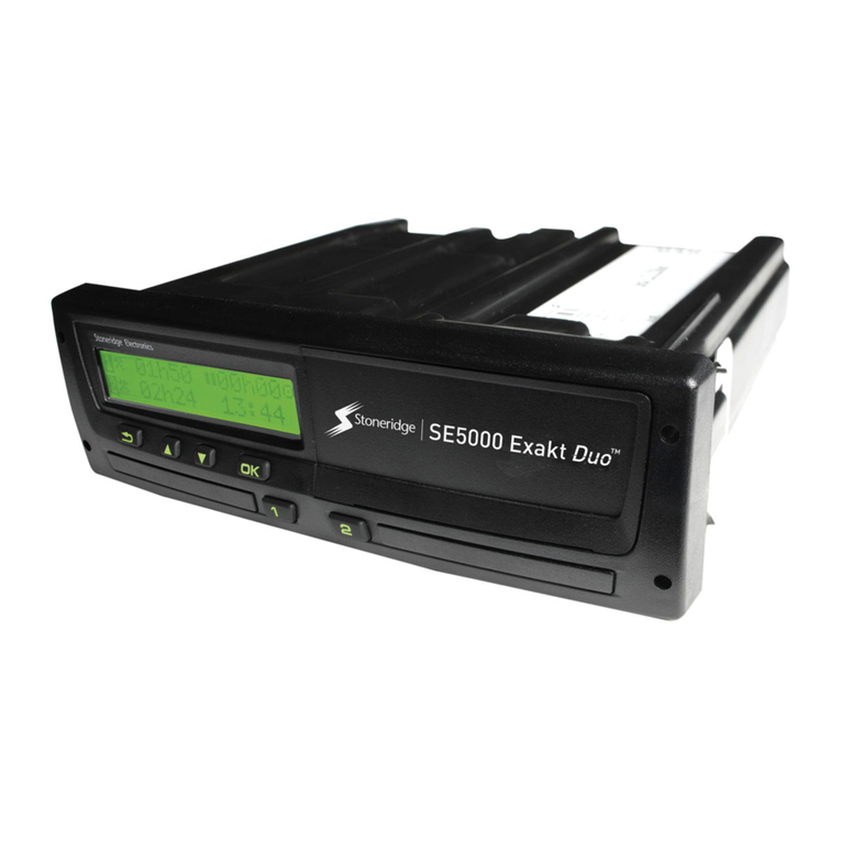
Stoneridge SE5000 User manual
Stoneridge
Stoneridge SE5000-8.1 User manual
Stoneridge
Stoneridge SE5000-8 User manual

Stoneridge
Stoneridge ELD1.0 User manual
