Stoneridge ORLACO Sets MirrorEye MP User guide

Sets MirrorEye MP
System manual
No. SM0974203 A 02
Article Number Sets: 0415000
0415010
0415020
5/2019
English

2SM0974203 A 02
System manual
Preface
Before you start installing this equipment, please read this manual
carefully and follow all instructions. This system manual
describes the functions of the equipment, outlines the
connection options and explains how to put the equipment into
operation. We recommend that you keep this manual in a safe
place for reference purposes.
If you have any questions or issues concerning the operation
of this equipment, consult the relevant section in the manual or
contact Stoneridge⎮Orlaco.
All data subject to change without notice. All dimensions are
for commercial purpose only. The camera/Monitor systems
from Stoneridge⎮Orlaco comply with the latest CE, ADR, EMC
and mirror-directive regulations, where applicable. All products
are manufactured in accordance with the ISO 9001 quality
management system, IATF 16949 quality automotive, ISO 14001
environmental management systems, where applicable.
Safety
In order to guarantee safe operation, these safety
instructions must be read before you start using this
equipment.
• Do not open the enclosure. This can cause damage, short-
circuiting or electrical shocks.
• Do not expose the equipment to extreme temperatures.
This can cause deformation of the enclosure or damage to
internal components.
• Repairs may only be undertaken by Stoneridge⎮Orlaco.
• The equipment must be assembled as shown in this manual.
• If there have been alterations or changes to this equipment that
have not been specifically approved by Stoneridge⎮Orlaco, use
of this equipment is not permitted.
• The use of this system while driving is only permitted by
persons who are (legaly) authorized to operate the vehicle and
are considerd fysical capable of driving a vehicle.
• Note that regulations must be obliged on all times.
• Check proper functioning of the system before driving.
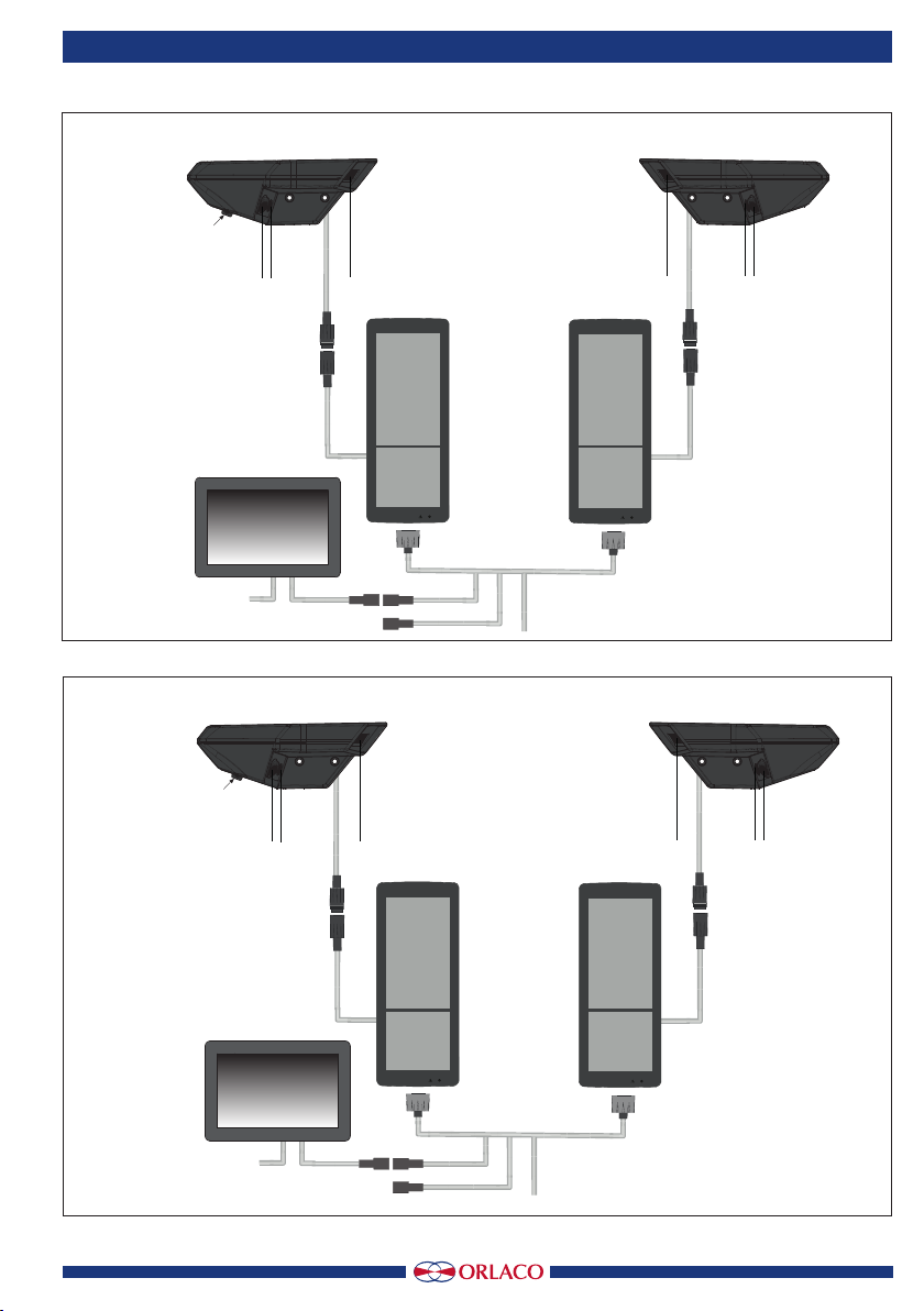
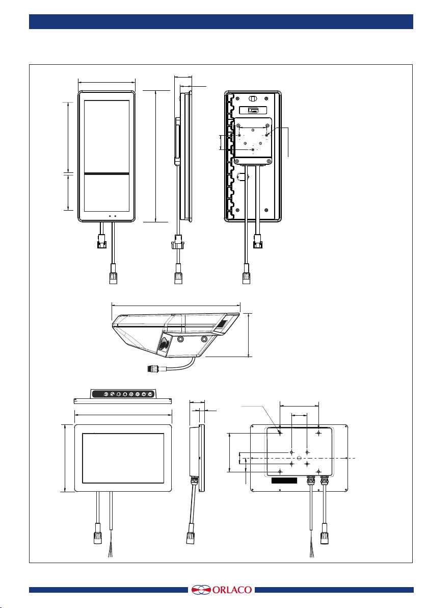
Sets MirrorEye MP
Manual No. IM0974203, A 02
Article Number sets: 0415000, 0415010, 0415020
MirrorEye sets
Also consult the following documents
Data sheet DS0965000
Data sheet DS0962201-0224000
User Manual UM0972203
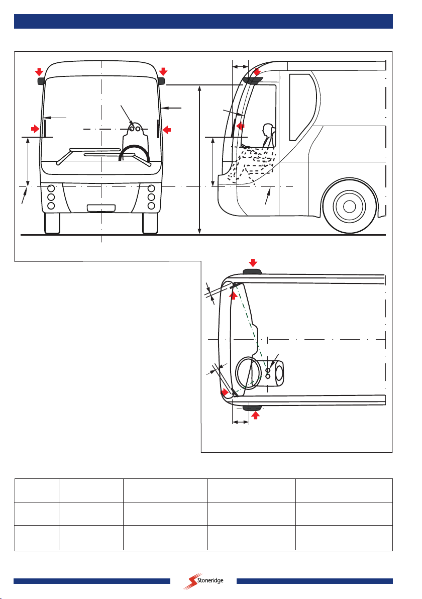
Checking Field of view
Remark:
Before driving it’s manda-
tory the driver/operator of the
vehicle checks if the legally prescribed eld
of view is displayed on the monitor.
Display of the system:
Warning:
The system is designed to meet legal requi-
rements and to provide the most accurate
representation of a situation. However, the
display is not one-to-one due to system
properties.
The operator/driver remains at all times
responsible for the safe operation of the
vehicle and the assessment of situations
during driving and maneuvering.
UN Regulation 46
Uniform provisions concerning the approval of devices for indirect
vision and of motor vehicles with regard to the installation of these
devices.

3
SM0974203 A 02
System manual
Contents Page
1. Introduction 3
2. System description 4
2.1. System view 4
2.2. Set MirrorEye Layout 6
2.3. Camera and monitor mounting positions 6
2.4. MirrorEye installation 6
3. Cables and electrical connections 8
3.1. Cabin Wire Harness 8
3.2. Cable 1m UNI Digicoax 8
4. Dimensions 9
5. Drilling template 10
6. Specifications 11
7. Possible faillures 12
7.1. Diagnostic information needed 13
7.2. Test pattern 13
8. Maintenance and cleaning 13
9. Disposal 13
10. General terms and conditions 13
11. Version details 14
1. Introduction
The MirrorEye MP system is used as a camera monitor system to
replace the conventional class II and class V rear-view mirrors, and
for on-road heavy duty application in Europe and North America
and complies with the regulations as described in R46R6.
System description
The function of the MirrorEye system is to show the legal Field of
View of class II and class V to the driver. See figure 1.
Class II
The class II field of vision for the main rear-view device according
to R46R6 shows the driver the rear vision next to the Vehicle
towards the horizon.
Class IV
The class IV field of vision for the wide-angle view device
according to R46R6 shows the driver the wide angle rear
vision next to the Vehicle.
Class V
The class V field of vision for the passenger side view de-
vice according to R46R6 shows the driver the field of vision
of a flat horizontal portion of the road along the passenger
side of the vehicle.
Driver
Ocular
Points
Driver
Ocular
Points
4m
Class IV
Class II
Class V
30m
1m
Ground level
Ground level
1m
15m
4,5m
25m
10m
1,5m
Ground level
Ground level
5m
2m
1
1,75m
3m
R=2m
4,5m
Larger Required View
Existing Class V Mirror View
Figure 1

4SM0974203 A 02
System manual
2. System description
Set MirrorEye, Art. No. 0415000
System overview
Camera MirrorEye Left side
Art. No. 0106040 Camera MirrorEye Right side
Art. No. 0106050
II II
IV IV
Class II camera
Class IV camera
IR Leds
Cabin Wire Harness
Art. No. 1002332
Open wire
Power input 12/24V/DC
Monitor 12,3”
Passenger side
Art. No. 0212500
Monitor 12,3”
Driver side
Art. No. 0212000
Not in use
Not in use
Class II camera
Class IV camera
IR Leds
2.1. System view see figure 2, 2a, 2b.
The MirrorEye system set consists of:
- 2 Camera units; each including two image sensors for class II/IV Monitor, video processor, video channel
transceiver with bidirectional communication, heating, bracket and covers. One camera unit mounted on the left
top on the outside of the Vehicle and one camera mounted on the right top on the outside of the Vehicle.
- 2 Monitor units each with a 12.3-inch Monitor for class II/IV image, video channel receiver with bidirectional
communication, Monitor processor, state machine, diagnostics, CAN communication with vehicle, MirrorEye
internal CAN communication, housing and bracket. Mounted inside the Vehicle, one mounted on the A-pillar on
the driver’s side and one mounted on the A-pillar on the passenger’s side.
- 1 Monitor unit 10” for class V image, Monitor processor, full On-Screen-Display (OSD), Auto Brightness Control
(ABC), housing and bracket. Mounted inside the Vehicle on dashboard.
- Cabin Wire Harness. The vehicle electrical connections are at the Monitor unit. The internal connections are
composed of coax, power and ground cables. The coax cable is used for both video channel and bidirectional
communication. The bidirectional communication is operational with and without active video channel.
Figure 2

5
SM0974203 A 02
System manual
Class V camera
Set MirrorEye MP RHD (Class V Left), Art. No. 0415010
System overview
Camera MirrorEye Left + V
Art. No. 0106060 Camera MirrorEye Right
Art. No. 0106050
II II
IV IV
Class II camera
Class IV camera
IR Leds
Cabin Wire Harness
Art. No. 1002332
Open wire
Power input 12/24V/DC + CAN
Monitor 12,3”
Passenger side
Art. No. 0212500
Monitor 12,3”
Driver side
Art. No. 0212000
Monitor 10”
Dashboard
Art. No. 0224000
Not in use
Class II camera
Class IV camera
IR Leds
V
Class V camera
Set MirrorEye MP LHD (Class V Right), Art. No. 0415020
System overview
Camera MirrorEye Left
Art. No. 0106040 Camera MirrorEye Right + V
Art. No. 0106070
II II
IV IV
Class II camera
Class IV camera
IR Leds
Cabin Wire Harness
Art. No. 1002332
Open wire
Power input 12/24V/DC + CAN
Monitor 12,3”
Passenger side
Art. No. 0212500
Monitor 12,3”
Driver side
Art. No. 0212000
Monitor 10”
Dashboard
Art. No. 0224000
Not in use
Class II camera
Class IV camera
IR Leds
V
Figure 2a
Figure 2b

6SM0974203 A 02
System manual
1
2
3
4
1
2
3
4
1
2
Ocular Reference Point
45
30 Ocular Reference Point
A Pillar
A Pillar
A Pillar
Dimensions in mm
200
3100
Seat rails 745
745
Seat rails
200
2.2. Set MirrorEye Layout See Figure 3
1. Camera MirrorEye Left Side; Article No. 0106040
2. MirrorEye 12.3” Monitor unit, Driver;
Article No. 0212000
3. Camera MirrorEye Right Side; Article No. 0106050
4. MirrorEye 12.3” Monitor unit, Passenger;
Article No. 0212500
2.3. Camera and monitor mounting positions
The camera position must as far to the front of the Vehicle
as possible to ensure that the class IV image can be
captured, see also figure 1, page 3. For drilling template
camera bracket see page 9.
The monitor position can be determined according to the
table below and the dimensions according to figure 3.
Optimum viewing angle while driving
Class Location Design viewing Design viewing Distance ORP
angle horizontal angle vertical to monitor
Class II driver 5° -17,5° 50 cm
Class IV driver 5° 17,5° 50 cm
Class II passenger 5° -7,1° 120 cm
Class IV passenger 5° 7,1° 120 cm
Figure 3

7
SM0974203 A 02
System manual
2.4. MirrorEye installation
Advise:
We strongly advise to contact your Stoneridge⎮Orlaco dealer for
detailed instructions regarding the installation.
The MirrorEye system is developed as a mirror replacement as
mentioned in UNECE R46 regulation.
In order to use the MirrorEye system as a mirror replacement the
installation needs to be approved by the authorized body.
Warning:
Without installation- or type approval it’s prohibited
to use the MirrorEye system without mirrors
mounted on the vehicle.
Remark:
When mirrors are replaced by the MirrorEye system;
installation approval according to R46 is required.
For legal requirements see:
https://www.unece.org/fileadmin/DAM/trans/main/wp29/wp29regs/2016/R046r6e.pdf
The positioning and placement of the cameras and monitors is
essential for a proper use of the system. Without a correct installa-
tion the installation approval is not possible.

8SM0974203 A 02
System manual
Front side 9p
Female connector
To MirrorEye
Driver side
Camera +
Monitor Class II, IV
Front side 9p
Female connector
To MirrorEye
Passenger side
Camera +
Monitor Class II, IV
4
1
3
2
Front side
4p Deutsch DT
Female connector
Not in use
456
123
1 = Power (KL30)
2 = GND
4 = Ignition (KL15)
3 = CAN H (J Stick)
6 = CAN L (J Stick)
Power (KL30)
CAN 1H
CAN 1L
GND
Ignition (KL15)
CAN 3H
CAN 3L
Open Wire
To vehicle power + CAN
1 = Power (KL30)
2 = GND
3 = CAN H (J Stick)
4 = CAN L (J Stick)
3 = Power (KL30)
1 = CAN 1H
2 = CAN 1L
4 = CAN H (J Stick)
5 = CAN L (J Stick)
7 = CAN 3H
8 = CAN 3L
6 = GND
9 = Power (KL15)
3 = Power (KL30)
1 = CAN 1H
2 = CAN 1L
4 = CAN H (J Stick)
5 = CAN L (J Stick)
7 = CAN 3H
8 = CAN 3L
6 = GND
9 = Power (KL15)
Cabin Wire Harness ME 2.4m; Art. No. 1002332
456
123
1 = Power (KL30)
2 = GND
4 = Ignition (KL15)
3 = CAN H (J Stick)
6 = CAN L (J Stick)
Front side 6p
male connector
Not in use
Front side 6p
male connector
Not in use
3
1
7
93
1
7
9
Figure 4
The Set MirrorEye MP must be connected by
trained electricians. Under no circumstances
should you make connections that are not
described in this manual.
3. Cabin Wire Harness electrical connections

9
SM0974203 A 02
System manual
Units in mm
Units in mm
Bracket Drilling template MirrorEye MP Left, SCALE 1:1
149,5
341,5
30,2
45,2
70,5
37,4
Mounting holes for bracket
3x M5
Monitor 12,3” MirrorEye
Monitor 10” HLED 1
Monitor active part
Class II
190 x 110mm
Class IV
95 x 110mm
332
Camera MirrorEye MP Left side/Right side
5p Molded male
Connector
114
62
20
27
∅9 Mounting holes for bolts M8
251
37,5
13,5
173
100
100
30
35,2
M5 (8x)
40
Class V
Figure 5
4. Dimensions

10 SM0974203 A 02
System manual
Figure 6
5. Drilling template
Units in mm
Units in mm
Bracket Drilling template MirrorEye MP Left, SCALE 1:1
149,5
341,5
30,2
45,2
70,5
37,4
Mounting holes for bracket
3x M5
Monitor 12,3” MirrorEye
Monitor 10” HLED 1
Monitor active part
Class II
190 x 110mm
Class IV
95 x 110mm
332
Camera MirrorEye MP Left side/Right side
5p Molded male
Connector
114
62
20
27
∅9 Mounting holes for bolts M8
251
37,5
13,5
173
100
100
30
35,2
M5 (8x)
40
Class V

11
SM0974203 A 02
System manual
Camera Units
Camera MirrorEye MP Left Camera Mirror Eye MP Right Camera Mirror Eye MP Left+V Camera Mirror Eye MP Right+V
Article numbers 0106040 0106050 0106060 0106070
Camera module Two image sensors for Class II/IV view, 1.4MP.
Video sensor Uncompressed over Coax cable (3Gbps).
Night Vision Active Day/Night filter + IR LED.
Ingress protection IP69K
Optic Class II H/V: 45/30 deg. Class IV H/V: 90/120 deg.
Video output Coax connection on Camera Unit.
Weight 1,66Kg/part.
Monitor 12,3” MirrorEye
Monitor driver side Monitor passenger side
Article numbers 0212000 0212500
Backlight TFT LED
Luminance Min 800cd/m2
Display module 12,3” (diagonal size), 720 x 1223 pixels for Class II image, 720 x 617 pixels for IV image, diagnostics.
Bracket Universal fastening for easy assembly to most vehicles.
Ingress protection IP54
Communication cam.-mon. High speed bi-derectional over Coax cable, operational with active video channel.
Communication vehicle CAN.
Aspect ratio Portrait 3 : 8.
Frame rate 60 fps.
Weight 1,92Kg/part. (Incl. cable)
Cabin Wire Harness ME 2.4m
Article number 1002332
Electrical connections All vehicle electrical connections are at the monitor.
The internal connection at each side is composed of CAN communication wires, coax, power and ground cables.
The coax cable is used for both video channel and bidirectional communication.
General
Mechanical tested and suitable for automotive applications.
Operating temperature -40°C - +85°C, (nighttime: +40°C with IR illumination).
Power supply 12...32V.
Power consumption Max 96W, 4A@24V. We advise to use a fuse op 10A.
Documentation User Manual UM0972203, System Manual SM0974203.
Product identication C-01:M-01:O-01:S-01:V-02
Compliance R46R6
EMC
CE certification
ISO-16750:2006-2012
ergonomic requirements
RoHS
Vibration resistance camera unit: 3G
6. Technical specications
6.1. Set MirrorEye MP; Art. No. 0415000

12 SM0974203 A 02
System manual
Camera Units
Camera MirrorEye MP Left + V Camera Mirror Eye MP Right
Article numbers 0106060 0106050
Camera module Two image sensors for Class II/IV view, 1.4MP.
Video sensor Uncompressed over Coax cable (3Gbps).
Night Vision Active Day/Night filter + IR LED.
Ingress protection IP69K
Optic Class II H/V: 45/30 deg. Class IV H/V: 90/120 deg.
Video output Coax connection on Camera Unit.
Weight 1,66Kg/part.
Monitor 12,3” MirrorEye
Monitor driver side Monitor passenger side
Article numbers 0212000 0212500
Backlight TFT LED
Luminance Min 800cd/m2
Display module 12,3” (diagonal size), 720 x 1223 pixels for Class II image, 720 x 617 pixels for IV image, diagnostics.
Bracket Universal fastening for easy assembly to most vehicles.
Ingress protection IP54
Communication cam.-mon. High speed bi-derectional over Coax cable, operational with active video channel.
Communication vehicle CAN.
Aspect ratio Portrait 3 : 8.
Frame rate 60 fps.
Weight 1,92Kg/part. (Incl. cable)]
Monitor 10” HLED 1
Article number 0224000
Specications See DS0962201
Cable 2m UNI Digicoax
Article number 0311010
Weight 0,12kg.
Connectors Molded M16 4p + Coax.
Cable Art. no. 1220180; Cable Base 6,8B - 1C50B4W
Temperature range -40°...+85°C.
Min. bending radius 7.5 O.D.
Coax Nominal impedance 50Ω
Approvals Flame: IEC 60332-2, Oil resistant; EN50363-10, Halogen free; IEC60754-1.
Cable Cabin Harness ME 2.4m
Article number 1002332
Electrical connections The coax cable is used for the video channel, bidirectional communication and providing power to the camera.
The internal connection at each side is composed of CAN communication wires, power and ground cables.
General
Mechanical tested and suitable for automotive applications.
Operating temperature -40°C - +85°C, (nighttime: +40°C with IR illumination).
Power supply 12...32V.
Power consumption Max 96W, 4A@24V. We advise to use a fuse op 10A.
Documentation User Manual UM0972205, System Manual SM0974205.
Product identication C-01:M-01:O-01:S-01:V-02
Compliance R46R6
EMC
CE certification
ISO-16750:2006-2012
ergonomic requirements
RoHS
Vibration resistance camera unit: 3G
6.2. Set MirrorEye MP RHD (Class V Left); Art. No. 0415010

13
SM0974203 A 02
System manual
Camera Units
Camera MirrorEye MP Left Camera Mirror Eye MP Right + V
Article numbers 0106040 0106070
Camera module Two image sensors for Class II/IV view, 1.4MP.
Video sensor Uncompressed over Coax cable (3Gbps).
Night Vision Active Day/Night filter + IR LED.
Ingress protection IP69K
Optic Class II H/V: 45/30 deg. Class IV H/V: 90/120 deg.
Video output Coax connection on Camera Unit.
Weight 1,66Kg/part.
Monitor 12,3” MirrorEye
Monitor driver side Monitor passenger side
Article numbers 0212000 0212500
Backlight TFT LED
Luminance Min 800cd/m2
Display module 12,3” (diagonal size), 720 x 1223 pixels for Class II image, 720 x 617 pixels for IV image, diagnostics.
Bracket Universal fastening for easy assembly to most vehicles.
Ingress protection IP54
Communication cam.-mon. High speed bi-derectional over Coax cable, operational with active video channel.
Communication vehicle CAN.
Aspect ratio Portrait 3 : 8.
Frame rate 60 fps.
Weight 1,92Kg/part. (Incl. cable)
Monitor 10” HLED 1
Article number 0224000
Specications See DS0962201
Cable 2m UNI Digicoax
Article number 0311010
Weight 0,12kg.
Connectors Molded M16 4p + Coax.
Cable Art. no. 1220180; Cable Base 6,8B - 1C50B4W
Temperature range -40°...+85°C.
Min. bending radius 7.5 O.D.
Coax Nominal impedance 50Ω
Approvals Flame: IEC 60332-2, Oil resistant; EN50363-10, Halogen free; IEC60754-1.
Cable Cabin Harness ME 2.4m
Article number 1002332
Electrical connections The coax cable is used for the video channel, bidirectional communication and providing power to the camera.
The internal connection at each side is composed of CAN communication wires, power and ground cables.
General
Mechanical tested and suitable for automotive applications.
Operating temperature -40°C - +85°C, (nighttime: +40°C with IR illumination).
Power supply 12...32V.
Power consumption Max 96W, 4A@24V. We advise to use a fuse op 10A.
Documentation User Manual UM0972205, System Manual SM0974205.
Product identication C-01:M-01:O-01:S-01:V-02
Compliance R46R6
EMC
CE certification
ISO-16750:2006-2012
ergonomic requirements
RoHS
Vibration resistance camera unit: 3G
6.3. Set MirrorEye MP LHD (Class V Right); Art. No. 0415020

14 SM0974203 A 02
System manual
Symptom Action driver
1. Black screen 1. Driver should stop the vehicle in a safe manner,
as soon as possible.
2. Blue screen 2. Driver should stop the vehicle in a safe manner,
as soon as possible.
3. Overlay menu not available 3. Driver should assess the problem and stop
vehicle if necessary.
4. Test pattern shown (image see page 14) 4. Driver should stop the vehicle in a safe manner,
as soon as possible.
5. Mirrored image 5. Driver should stop the vehicle in a safe manner,
as soon as possible.
6. Flipped image 6. Driver should stop the vehicle in a safe manner,
as soon as possible.
7. Full in screen deformation of image 7. Driver should stop the vehicle in a safe manner,
as soon as possible.
8. Partly in screen deformation of image 8. Driver should assess the problem and stop
vehicle if necessary.
9. Color representation of image wrong 9. Driver should assess the problem and stop
vehicle if necessary.
10. Incorrect image cropping and scaling 10. Driver should assess the problem and stop
vehicle if necessary.
11. Incorrect image sharpness 11. Driver should assess the problem and stop
vehicle if necessary.
12. Corrupted image stream due to Electric 12. Driver should assess the problem and stop
Magnetic Interference (EMI) vehicle if necessary
13. Wrong placement of camera views on monitor 13. Driver should assess the problem and stop
vehicle if necessary.
14. Image too bright 14. Driver should assess the problem and stop
vehicle if necessary.
15. Image too dark 15. Driver should assess the problem and stop
vehicle if necessary.
When the mentioned failures occur;
the driver must stop the Vehicle
and no further driving is allowed
before the failures are resolved.
7. Possible failures:
In the event of a failure
in the MirrorEye system;
contact your dealer.
CONTINUED NEXT PAGE

15
SM0974203 A 02
System manual
7.1. Diagnostic information needed:
• Trouble Condition – To diagnose problem and deter-
mine if it requires Scheduled Maintenance Service or it
is an Out of Service Condition.
• VIN (to identify vehicle and MirrorEye component
serial numbers).
• Asset Number.
• Location.
• Incident contact person phone number.
7.2. Test pattern (Figure 13)
See possible failure; No. 4 on page 11.
8. Maintenance and cleaning
Passive cleaning ensures that the camera lenses stay clean, using a
coating on the glass.
Heating ensures that the camera lenses stay clear of ice and fog by
automatically heating them and evaporating water in front of the
camera lenses.
Use a high quality and safe detergent and a soft cloth to remove
dirt etc. from the lenses.
Do not clean this product with aggressive chemicals or
abrasive cleaning agents.
9. Disposal
Disassembly, removal and disposal. Local regulations for dealing
with waste must be followed when disposing of disassembled
components or entire units.
10. General terms and conditions
Stoneridge⎮Orlaco Products BV is not liable for damage resulting
from inadequate servicing, incorrect usage or alterations made to
the equipment without informing the manufacturer in writing.
This installation manual has been made available by
Stoneridge⎮Orlaco.
All rights reserved. No part of this manual may be reproduced and/
or made public in printed form, in photocopy form or on microfi
lm, or in any other way, without the prior written permission of
Stoneridge⎮Orlaco. This also applies to the associated drawings
and figures.
Stoneridge⎮Orlaco reserves the right to make changes to com-
ponents at any time without informing customers beforehand or
directly. All dimensions given are for commercial purposes.
Figure 13

16 SM0974203 A 02
System manual
For information regarding repairs that is not covered in this
manual, please contact the Stoneridge⎮Orlaco Products BV service
department.
This manual has been prepared with all due care and attention.
However, Stoneridge⎮Orlaco cannot be held responsible for any
errors in this manual or any consequences thereof.
11. Version details
Version A 01. First issue May 2019.
Version A 02. Various adjustments, January 2020.

17
SM0974203 A 02
System manual

18 SM0974203 A 02
System manual

19
SM0974203 A 02
System manual

www.stoneridge.com
www.orlaco.com
ORLACO
Orlaco is a Manufacturing company that specializes in making cameras and
monitor systems for commercial vehicles, fork-lift trucks, cranes, off shore
and maritime.
Our objective is to design and produce camera systems for the professional
market that improve the drivers’ view and increase operating efficiency.
At our facility in Barneveld we locate our design, manufacturing, ware-
housing and service department.
Vision is our mission®. Orlaco therefore deploys the development, manu-
facture, supply and service of camera and Monitor systems that will improve
safety and efficiency of all vehicles, machinery and vessels.
Our systems give the end user a view on each blind spot and will create
comfort and improved working conditions. Our active approach will support
market demands and innovations and will lead to enthusiastic ambassadors
in the market; our customers.
For more information: www.Stoneridge.com and www.orlaco.com
This manual suits for next models
3
Table of contents
Other Stoneridge Automobile Accessories manuals

Stoneridge
Stoneridge MirrorEye 0416100 User guide

Stoneridge
Stoneridge SE5000-8.1 User manual

Stoneridge
Stoneridge SE5000 Use and maintenance manual

Stoneridge
Stoneridge SE5000 User manual

Stoneridge
Stoneridge ELD1.0 User manual

Stoneridge
Stoneridge SE5000-8 RG User manual

Stoneridge
Stoneridge Optac 3 User manual

Stoneridge
Stoneridge SE5000-8 User manual