Strapack RQ-8Y User manual

MODEL RQ-8Y
INSTRUCTION MANUAL
I M P O R T A N T
DO NOT DESTROY
*Read carefull
y
and understand SAFETY INSTRUCTIONS
before o
p
eratin
g
y
our Stra
p
ack machine.
*Kee
p
this instruction manual in a convenient locatio
n
for use at an
y
time.
A/E Spec.
904-1A-02002-02
Serial №
Tel: 800-821-2177/ Fax: 913-322-1729
www.MillerBevco.com


Contents
Preface ・・・・・・・・・・・・・・・・・・・・・・・・・・・・・・・・・・・・・・・・・・・・・・・・・・・・・・・・・ 1
For Safe Operation ・・・・・・・・・・・・・・・・・・・・・・・・・・・・・・・・・・・・・・・・・・・・・ 2
Location and Function of Units ・・・・・・・・・・・・・・・・・・・・・・・・・・・・・・・ 3
Safety Alert Labels ・・・・・・・・・・・・・・・・・・・・・・・・・・・・・・・・・・・・・・・・・・・・
・
4
Precautions for installation ・・・・・・・・・・・・・・・・・・・・・・・・・・・・・・・・・・・
・
5
Precautions for Operation ・・・・・・・・・・・・・・・・・・・・・・・・・・・・・・・・・・・・
・
6
Operation Switch ・・・・・・・・・・・・・・・・・・・・・・・・・・・・・・・・・・・・・・・・・・・・・・・
・
7
Threading Strap ・・・・・・・・・・・・・・・・・・・・・・・・・・・・・・・・・・・・・・・・・・・・・・・・ 9
Adjustments
Amount of Strap in Pool Box ・・・・・・・・・・・・・・・・・・・・・・・・・・・・・・・・ 11
Home Position (Cycle-Start Position) ・・・・・・・・・・・・・・・・・・・・・ 12
Feed and Reverse Mechanism ・・・・・・・・・・・・・・・・・・・・・・・・・・・・・・ 13
Limit Switches ・・・・・・・・・・・・・・・・・・・・・・・・・・・・・・・・・・・・・・・・・・・・・・・・・・ 14
Control Group ・・・・・・・・・・・・・・・・・・・・・・・・・・・・・・・・・・・・・・・・・・・・・・・・・・
・
15
LED Indicators ・・・・・・・・・・・・・・・・・・・・・・・・・・・・・・・・・・・・・・・・・・・・・・・・・ 16
Troubleshooting Guid ・・・・・・・・・・・・・・・・・・・・・・・・・・・・・・・・・・・・・・・・・・ 17
Electrical Wiring (A Spec.) ・・・・・・・・・・・・・・・・・・・・・・・・・・・・・・・・・・・・
・
18
Electrical Wiring (E Spec.) ・・・・・・・・・・・・・・・・・・・・・・・・・・・・・・・・・・・・・ 20

Preface
Thank you very much for your purchase of a STRAPACK STRAPPING MACHlNE.
We are prepared to offer extensive after sales service for our products through
our distribution network. To effectively use the strapping machine, daily maintenance
and proper handling are important.
You are requested to have a complete understanding of this instruction manual for
proper use and maintenance of the machine over a long period of time.
Also,
p
lease carefull
y
read the se
p
arate leaflet " Check that Seal ! ", to
p
revent an
y
accidents durin
g
o
p
eration.
● Standard Accessories
Description Quantity
Instruction Manual 1
Parts List 1
Check that Seal 1
Tools 1 set
-1-

For Safe Operation
This important Instruction Manual has been prepared to provide you for
safe operation, easy maintenance and safety information relating to your machine.
It is essential that you carefully read ”For Safe Operation” and understand it
before you attempt to operate your machine.
In this manual, a warning symbol is used to call attention to hazards.
Be especially careful to read the items next to this symbol.
In this manual, WARNING and CAUTION are defined as follows:
Personal Danger
WARNING indicates a potentially hazardous situation which,
if not avoided, could result in death or moderate injury.
Possible dama
g
e to e
q
ui
p
ment
CAUTION indicates a
p
otentiall
y
hazardous situation which,
if not avoided, ma
y
result in minor or moderate in
j
ur
y
.
The alert labels shown below are attached to machine:
WARNING to the electric
p
arts
Hazardous volta
g
e can use electric shock. Turn off Power Su
pp
l
y
Switch before removin
g
U
pp
er Table for servicin
g
. Do not touch
Control Box, Main Transformer, Heater Transformer and Transformer
for I.C. Board while
p
ower on.
Do not touch ex
p
osed Power Su
pp
l
y
Cord.
WARNING to Arch Unit
Do not
p
ut head, hand and an
y
p
art of bod
y
into arch.
Runnin
g
stra
p
can cause in
j
ur
y
.
WARNING to Heater in Sealing Unit
Hi
g
h Tem
p
erature (about 400℃) of Heater can burn.
Do not touch Heater.
WARNING
CAUTION
Do not put head,hand
WARNING
and any part of body
into arch.
Running strap can
cause injury.
-2-

Location and Function of Units
Fig. 1
Arch Unit
This is the arch track through
which strap forwards and
reverses.
Control Group
Contains timers, fuses,
I.C. Boards, etc.
Power Supply Switch
Electric Group
Includes motors, transformer.
switches, etc.
Reel Uni
t
Dispenses strap.
Body Unit
Comprises machine frame,
castors, upper tables, etc.
Pool Unit
Pools strap for smooth
forwarding through arch track.
Sealing Unit
This part of the mechanism
cuts and seals strap.
-3-
Tel: 800-821-2177/ Fax: 913-322-1729
www.MillerBevco.com

Safety Alert Labels
The Safety Alert Labels are attached to machine.
Location and meaning of these labels are explained below :
Read carefully Instructions on Safety Alert Labels and follow them.
Replace missing or damaged safety labels with new safety labels.
If safety labels are replaced with new labels, make sure new safety
labels are attached in the same location as the replaced labels.
Donotputhead,hand
andanypartofbody
intoarch.
Runningstrapcan
causeinjury.
WARNING
Fig. 2
-4-

Precautions for installation
WARNING
Do not lay the power supply cord across any path where vehicles or
people are likely to walk on it drive over it. The insulation might be
damaged and expose wires which can cause electrical shock.
WARNING
Position the power supply cord where nothing will damage the cord
or break the insulation, e,g., Strapping Coil. A damaged cord can
cause an electrical shock. Replace the cord if the insulation
becomes frayed or broken.
WARNING
Do not handle the power supply cord or power plug with wet hands.
You may receive an electric shock.
WARNING
Handle the polypropylene strapping with care. The sharp edges on
the straps could cut your hands.
WARNING
Lock the casters unless the machine is being moved.
WARNING
Make sure to push the machine in order to move it. Do not pull on the
machine. Pulling on the machine may cause injury.
WARNING
Do not modify the machine. Modifications lead to machine malfunctions
and may cause injuries.
WARNING
Make sure to connect the ground wire.
WARNING
Make sure to connect the power plug to a power outlet that is connected
with a leakage breaker.
CAUTION
Allowing water or oil to come into contact with the electrical wiring
inside the machine can cause a malfunction.
CAUTION
Use the specified cable for power cord.
CAUTION
Disconnect the power plug and wind the cord up when you need to
move the machine.
CAUTION
Do not move the machine b
y
p
ullin
g
on the
p
ower cord, as the
p
ower cord
ma
y
become disconnected, or broken.
CAUTION
Do not
p
erform an
y
work not s
p
ecified in this manual.
-5-

Precautions for Operation
WARNING
Do not remove an
y
safet
y
covers. Do not
p
ut
y
our hands or fin
g
ers
into the machine from the bottom. The transformer
p
roduces ver
y
hi
g
h volta
g
e
,
and can cause serious electrical shocks. Also
,
contact
with an
y
of the rotatin
g
p
arts mi
g
ht cause serious in
j
uries.
WARNING
Do not
p
ut
y
our head
,
hands or other bod
y
p
arts into the Arch while
the machine is o
p
eratin
g
. The machine o
p
erates ver
y
fast and can
cause serious in
j
uries.
WARNING
Do not o
p
erate switches on the o
p
eration
p
anel while
y
ou are holdin
g
a reel or
p
art of
y
our bod
y
or wear is touchin
g
it.
WARNING
Do not carr
y
or unload
p
acka
g
es with
p
ullin
g
stra
p
s on them. The stra
p
s
ma
y
break and the
p
acka
g
e will fall down
,
and
y
ou will be in
j
ured.
Dail
y
check the s
p
ecified
p
oints b
y
referrin
g
the check card decal Su
pp
lie
d
with the machine.
WARNING
Do not touch the Slide Table or Sealin
g
Unit Drive Section durin
g
the
o
p
eration. This can cause serious in
j
uries.
WARNING
Do not touch the V-Belt while it is runnin
g
. This can cause serious in
j
urie
s
WARNING
Do not touch the Heater Plate. Its surface tem
p
erature reaches
around 400 de
g
rees centi
g
rade and will cause serious burns.
CAUTION
Lock the sto
p
switch or turn off the main switch when the machine
will not be o
p
erated for a lon
g
p
eriod. Also
,
it is recommended that
y
ou remove the PP stra
p
from the Pool Box when the machine will
not be used for alon
g
p
eriod.
CAUTION
After the dail
y
o
p
eration of the machine is com
p
lete
,
make sure to
lock the sto
p
switch and turn off the main switch. Make sure to clean
an
y
dust or
p
articles around the sealin
g
unit.
CAUTION
It is recommended that you use the Foot Switch or the Table Ball
Switch instead of the Start Switch when
y
ou have to hold a
p
acka
g
e
in both hands.
CAUTION
If
y
ou want to chan
g
e the stra
pp
in
g
material width
,
the attachment
must also be chan
g
ed. Ask a maintenance
p
erson to chan
g
e it for
y
ou.
-6-

Operation Switch
CAUTION
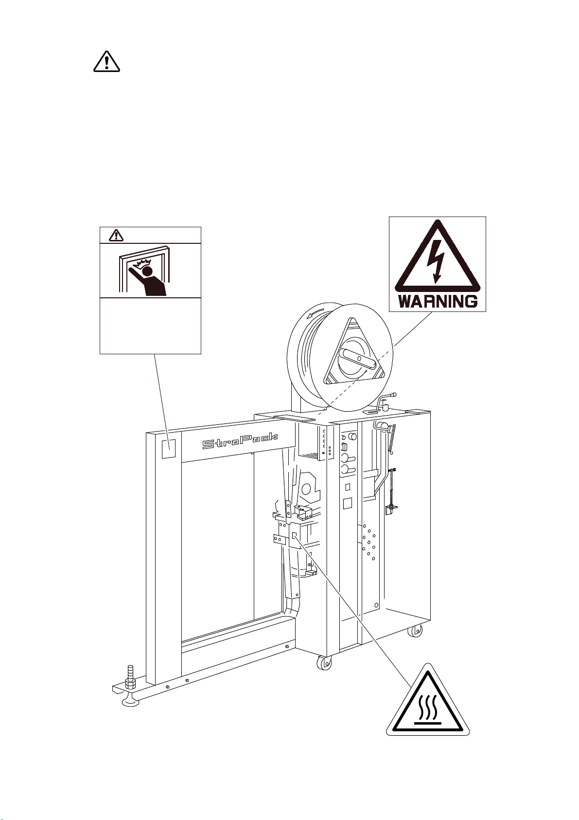
For the safety, Front Door is fixed with bolt.Turn OFF the Main Switch① when
it is opened.
①
Main Switch
Turning this switch on will supply the power to the machine.
②
O
p
eration Read
y
Switch and Power Indicator Lam
p
When the Power supply switch is turned on, the Power Indicator Lamp will
flash slowly. After the Heater Plates reaches operating temperature and
is ready to begin packaging, the lamp will flash quickly (Approximately
25 seconds after turning the machine on). Press the Operation Ready Switch
once, so that the lamp will change from flashing to a steady light.
While this indicator is blinking, the machine will not start a packaging operation,
even if you press the start button.
When the coil of strapping is completely exhausted, the Power Indicator Lamp
will start to flash slowly and the machine will come to a standstill automatically.
Remove the remaining strap from the Pool Box and mount a new coil of
strapping on the machine (refer to: How to thread the strapping material).
③
Tension Ad
j
ust Dial (T3)
The Tension Adjust Dial controls the strap tension. Although this model
has an adjustable tension stroke of 0 - 150 mm, the dial scale runs from 0
(minimum) to 10 (maximum), for the operator's convenience (for 5/6 mm
strapping, the tension stroke is 0 - 90 mm). Using this dial, set a suitable
strap tension according to the size of the package.
④
Start Switch
This step will initiate the strapping cycle. When the Start Switch is pressed,
one strapping operation cycle will start.
If no strapping operation takes place for 3 minutes, the Sealing Motor will
be shut off by an energy-saving circuit. To restart the Sealing Motor
turning, press the Start Switch. If a strapping cycle is not initiated, press
the switch again or, hold it down in order to activate The Sealing Motor and
start a strapping cycle at the same time.
⑤
Sto
p
Switch
Use the stop switch in emergency or whenever you want to stop the
strapping cycle before it is complete. When pressed, the Stop Switch will
lock. This switch will bring the machine to a complete and immediate stop.
However, unlike the Power Supply Switch, the Stop Switch does not
disconnect the Heater. Therefore, the operator can resume strapping at
any time without waiting for heater element to warm up again.
To resume operation, twist to release lock on the Stop Switch and press
the Operation Ready switch to re-start rotation of the sealing motor. The
lamp inside the Operation Ready Switch will change from flashing to a steady
light. Then the machine will be ready for strapping again. when the machine
will not be used for a period of time, Press this switch for added safety.
-7-

⑥ Forward/Reverse Switch (F/R SWITCH)
This switch provides manual control of the movement of the strap through
arch track. To move The strap forward through the arch, turn this switch
counterclockwise and hold it until the strap reaches the stopper under the
Slide Table. You can notice when the strap has reached the stopper
because a striking sound can be heard. When this switch is turned clockwise,
the strap will be reversed while it is turned.
When the daily strapping operation is complete, turn off the main power supply
and clean away any dust or waste materials around the sealing unit.
Do not touch the heater until it has cooled down completely.
Fig. 3
3
4
1
5
2
6
-8-
Tel: 800-821-2177/ Fax: 913-322-1729
www.MillerBevco.com

Threading Strap
Before loading new strapping material, make sure to press and lock
the Stop Switch and turn off the Power Supply Switch.
A safety switch is installation front door, for your safety.
When the Front Door is open, the start switch will not function.
1. Place the bound strapping coil (secured with plastic strings) on the Reel Center
Guides as shown by the direction the arrow is pointing (counterclockwise) on the
rear Reel In Circular ①. Then, put the front Reel Out Circular ② in place, and
secure it with the Reel Nut Handle ③.
2. Cut the plastic strings binding the coil.
3. Move Touch Lever ④ from position A (RUN) back to position B (LOADING) through
Lever Guide ⑤ so that the route of the loading strap is secured.
4. Thread the tip of the strap through Free Slide Roller ⑦ attached to Reel Brake Arm
⑥, and then through Free Slide Roller and Free Angle Roller ⑧. Then insert 15~25
cm of strap into the Pool Box Inlet ⑨.
5. Move the Touch Lever from position B (LOADING) to position A (RUN) through
Lever Guide.
6. Turn on the Power Supply Switch ⑩.
7. Unlock the Stop Switch ⑪ by turning it clockwise. Press the Operation Ready Switch
once, so that the strap is automatically pulled into the Pool Box and moved to the Strap
Feed Roller through the path.
Next, the strap will be inserted into the arch automatically and advanced to the specified
position.
This completes the strap intallation operation.
For details, see the “Operation Switch” on page 7.
WARNING
CAUTION
-9-

Strapping material
Operation Panel
Front Door
A
B
3
4
1
5
2
6
7
8
11
10
9
12
Fig. 4
-10-
Tel: 800-821-2177/ Fax: 913-322-1729
www.MillerBevco.com

ADJUSTMENTS
WARNING
Before servicing machine:
*Turn off Power Supply Switch
*Disconnect Power Supply Plug
● Adjustment of Strap Amount
As with other setting, the Pool Box intake of the machine was adjusted before delivery.
Some increase or decrease in strap volume, however, might later be advisable
depending on the thickness or stiffness of strap being use. If adjustment becomes
necessary, refer to illustation and proceed as follows:
●Turn off the Power Supply Switch. Open the Front
Door. Loosen the nut ③ on the Adjust Bolt ②, and
adjust the tension on Spring ④.
a. If the amount of strap contained in the Pool Box
is not lon
g
enou
g
h, lower the hei
g
ht of the
Ad
j
ust Bolt
②
.
b. If the amount of strap contained in the Pool Box
is too lon
g
, raise the hei
g
ht of the Ad
j
ust
Bolt
②
.
Tighten the Nut ③, and then close and rebolt the
Front Door.
★ LS-4 Limit Switch
⑤
When the amount of accumulated strap exceeds the
amount it is adjusted for, the Balance Bar ① moves
to right side and disengages LS-4. This stops the
Pool Motor. When the amount of accumulated straps
decreases, LS-4 is engaged, the Pool Motor will start
and more strap will be fed into the pool box.
Fig. 6
Fig. 5
Fig. 6
-11-

WARNING
Before servicing machine:
*Turn off Power Supply Switch
*Disconnect Power Supply Plug
● Ad
j
ustment of the Sealin
g
Unit to the home
p
osition
a. First press the Start Switch to run the machine for one complete strapping cycle.
Put a mark on Timing Plate ① using a marking pen or the like. Remember the
position of this mark.
b. Manually turn Magnet Brake ④ (BR1) so that
the arrow mark on it points left,
and so that the bearing center ② of the
Right Bandway Arm is aligned with the
center of the Right Bandway Cam hole ③ on
the same line.
c. The mark on the timing plate will move due
to the procedure above. Loosen screw ⑤,
and move the Timing Plate back to its
original position by referring to the mark
made on the plate. Then securely tighten
screw.
d. Turn on the Power Switch and press the
Start Switch. The machine will stop after one
cycle. After that, make sure that the arrow mark
on the Magnet approximately to the left (at 9
o'clock position or within 90 degrees).
If the arrow is within this range, the adjustment
is complete. See the drawing below.
Fig. 7
Fig. 8 Fig. 9
-12-

WARNING
Do not touch the V-belt while in operation, or your hand may be injured.
Before performing any maintenance, Lock the stop switch, turn OFF
the power switch, and disconnect the power.
● Feed and Reverse Mechanism
1. Ad
j
ustment the forward
p
ressure
a. To increase the pressure (View ”A”)
Loosen the lock nut ① and turn the reverse spring adjuster ② counterclockwise.
(Increase spring pressure ③)
b. To reduce the pressure (View ”A”)
Loosen the lock nut ① and turn the reverse spring adjuster ② clockwise.
(Decrease spring pressure ③)
2. Ad
j
ustment the reverse
p
ressure
a. To increase the pressure
Pull the pin ④ and turn the reverse spring adjuster ⑤ clockwise.
(Increase the reverse spring pressure ⑥)
b. To reduce the pressure
Pull the Pin ④ and turn the reverse spring adjuster ⑤ counterclockwise.
(Decrease the reverse spring pressure ⑥)
Fig. 10
-13-

Limit Switches
1. LS1 (Timin
g
)
This proximity switch detects the holes in the
Timing Plate and initiates the following movements;
When LS1 detects a hole, the switch is actuated and
the lamp (LS1) on the Control Box will light.
A: home position → B: reverse → C: release strap
tension when cut → D: extend the sealing time → A
2. LS2 (Home Position)
This proximity switch is activated when the
Sealing Unit Cam shaft is in the home position.
When LS1 and LS2 are in position (A), the home
position, at the same time, LS2 will send a signal
that the cycle is complete and also that the
Sealing Unit Cam shaft is in the home position.
When LS2 detects the hole on the Timing Plate,
the lamp (LS2) on the Control Box will light.
3. LS3 (End of Stra
p
)
This micro switch detects depletion of strap.
When the switch is actuated, the power
Indicator Lamp flashes and machine stops
after another one strapping is made.
Strap is not forwarded, the Sealing Motor
stops, and the Start Switch does not activate.
To resume operation, thread strap pf anew coil
according to "Loading Strap"
4. LS4 (Pool)
This micro switch detects and sends signal
that strap contained in the Pool Box is nearly
empty. When LS4 is activated, the lamp (LS4)
on the Control Box lights.
5. LS5 (Reversin
g
Pulse)
This proximity switch detects that reversing
of strap is completed and initiates tensioning.
Fig. 11
Fig. 12
Position of Limit Switch
-14-

Control Group
Adjustment of Volume
PRECAUTION; All the volume are preset at the factory, and normally should not need
adjustment.
If adjustment is necessary, follow the instruction below.
Pay attention that adjustment will be cause of trouble.
1. Heater Tem
p
erature Dial
The correct heater temperature is critical for a secure strap joint. To determine the best
setting, start with heater dial at position 3 or 4. Then, according to the results, gradually
adjust temperature until the strongest seal occurs consistently. Turn dial clockwise to
raise the temperature and counterclockwise to lower the temperature. For your safety,
we recommend to check the quality of the strap seal once a day. Factors such as
workroom temperature, strap thickness, and condition of the machine may affect the
resulting seal, but once properly set, heater temperature will rarely need adjustment.
Please carefully read the separate leaflet"CHECK THAT SEAL" in order adjust to the
heater temperature.
2. Reset Switch
When error lamp flashes or lights, depress this Reset Switch after correcting
cause of trouble.
3. Stra
p
Cast-off volume (T1)
This volume determines the timing that empty strap loop is cast off when the Start
Switch is pressed by accident without package. When tension is sometimes insufficient
to small package, turn this volume clockwise a little.
4. Forward Timer (T2)
Forward Timer controls the forwarding time of the strap. When the strap dose not reach
the stopper at the Sealing Head during continuous operation, turn this clockwise a little.
5. Fuse (5A)
The Fuse Holder is built into the top of the control box. Unscrew cap and replace fuse
when necessary. Replace only with 5 ampere fuse.
6. VR1
This timer is used to reduce noise which is occurred at cutting of strap after
tensioning. To make the noise lower, turn the volume clockwise. Note that strappings
peed will be slower as the volume is turned to right. If the volume is turned clockwise
too much, tension will become loose for hard or compressible packages.
7. VR2
This timer is used to adjust strap sealing time. If sealed straps are easily apart after
strapping, turn the volume clockwise slightly.
8. VR3
This timer adjusts time to send electric current to Heater in order to keep heater
temperature during continuous operation.
9. VR4
This is a volume of reversin
g
p
ulse to be used to detect incom
p
lete reversin
g
of stra
p
.
10. VR5
This timer controls the reverse time when incom
p
lete reversin
g
is occurred.
The timer works in connection with VR4.
-15-

LED Indicators
These indicators show the control box input/output status. (Fig. 13)
1. LS1:Timing
The LS1 counts holes in the timing plate. The LED lights each time the LS1
reads a hole.
2. LS2:Confirm zero position
The LS2 confirms the zero position.
The LED lights each time the LS2 reads a hole.
3. LS3:End of strapping material detected
The sensor detects the end of the coil of strapping material.
The LED lights when this sensor is activated.
4. LS4:Pool
The sensor detects that strapping material in the pool is almost the end.
The LED lights when this sensor is activated.
5. LS5:Reverse pulse
Lights with each count.
6. Spare
7. HEATER:Heater
The LED lights when the heater is supplied
with power.
8. M1:Sealing motor
Lights while this motor is turning.
9. M2:Pool motor
Lights while this motor is turning.
10. BR1:Sealing brake
Lights while the power is applied to the brake.
11. CL1:Sealing clutch
Lights while the power is applied to the clutch.
12. CL2:Secondary Tensioning clutch
Lights while the power is applied during the
secondary tensioning.
13. SOL1:Reverse solenoid
Lights while charged.
14. SOL2:Secondary tightening solenoid
Lights while it is operating.
15. SOL3:Forward solenoid
This LED goes out while in forward rotation.
16. SOL4:Spare
17. SFM:Smoke fan
Lights while it is turning.
18. START:Start
Lights while this button is pressed.
19. ERROR:Overload
Indicates that a motor is overloaded. Shows steady red light when the M1 motor
is overloaded. Shows a blinking red light when the M2 motor is overloaded.
20. A-LIMIT:Current limit, pool error
M1 motor overcurrent;Steady red light.
M2 motor
p
ool error;Blinkin
g
red li
g
ht.
Fig. 13
-16-

Troubleshooting Guide
WARNING Before servicing machine Turn off Power Supply Switch. Disconnect Power Supply cord.
1 No Power at outlet. 1 Check power source.
2 Fuse blown or dislodged. 2 Check Fuse. (P. 15)
Lamp Flashes 3 Quick Warm Heater circuit is activating. 3 Wait for 25 see., and press Start Switch. (P. 7)
4 Energy Saving Circuit is activating. 4 Press Start Switch once. (P. 7)
5 Motor overload. 5 Press Reset Switch.of Rear Operation Panel.
6 Stop Switch is locked. 6 Release the Stop Switch. (P. 7)
7 Poor connection at or within Start or Stop Switch. 7 Secure the connection or replace the Switch.
8 Improper threading of strap. 8 Re-shread the strap. (P. 9)
9 Insufficient or excessive strap in Pool Box. 9 Re-adjust the amount of strap poold. (P. 11)
10 Strap dust in Feed Unit. 10 Clean. (Fig. 14)
11 Tip of strap is cracked. 11 Adjust or replace Cutter Upper/Lower.
12 Strap jumps out from flaps. 12 Replace broken Arch Flap Spring.
13 Poor quality of strap. 13 Cut off the poor parts of strap,
or change strap coil.
14 Improper Home Position. 14 Readjustment of Timing Plate. (P. 12)
15 Short T2 timer setting. 15 Readjust the Feed timer. (P. 15)
16 Insufficient Feed pressure. 16 Readjust the Feed pressure. (P. 13)
Insufficient Reverse pressure. Readjust the Reverse pressure.
17 Stopper bolt is too long to transfer the reversing 17 Readjustment of Stopper Bolt.
pressure.
18 strap is folded and jammed. 18 Remove Band Guide Plate and Feed
Band Guide Plate to remove jammed
strap.
19 Heater wiring is damaged, Heater defective or 19 Replace Heater Blade, or clean
loos/disconnected at terminal. the blade when PP dregs are on
the blade.
20 Improper Heater temperature. 20 Readjust the heater temperature.
21 Strap does not reach at slide table. 21 Readjust the Home Position. (P. 12)
22 Heater Plate does not to be positioned between 22 Replace Heater Tension Spring or re-position the Heater.
straps.
23 Excessive tension for a package. 23 Readjust Tension Dial. Or, re-adjust VR2 volume. (P. 15)
24 T1 Timer is short for its setting. 24 Readjust T1 timer. (P. 15)
25 Defective T3 timer. 25 Replace T3 timer. (P. 7)
26 Improper positioning of package. 26 Re-position package.
Lamp lights.
Problem Causes Corrective Actions
Lamp does not
light.Start Button
pressed.
Machine does
not work.
PILOT LAMP;
Start Button
Pressed.
Machine Works, but
Irregular
forwarding/
reversing of
strap.
Strap
unsealed.
Improper
Tensioning
-17-
Feed Band Guide
Plate
Band Guide Plate
Fig. 14
Table of contents
Other Strapack Packaging Equipment manuals
Popular Packaging Equipment manuals by other brands

Hitech
Hitech NEL 216 Users Quick Reference

Greenbridge
Greenbridge PC1500 Operation manual & spare parts list

Fromm
Fromm AP210 Instruction and maintenance manual

Formech
Formech 450DT Installation, operating and service manual

Orgapack
Orgapack OR-H 47 operating instructions

Cushion Pack
Cushion Pack CP 320 S2i operating instructions

Martin Yale
Martin Yale Intimus PacMaster VS operating instructions

Atlantis
Atlantis TP-701 Operation manual & spare parts list

PACTUR
PACTUR Ladt Pack 45/N Instruction, use and maintenance manual

STOROpack
STOROpack AIRmove2 quick start guide

Lacor
Lacor 69430 Instructions for use and maintenance

Pregis
Pregis Quantum Pro 4068969 user manual