Extend EXS-206 Manual

SEMI-AUTOMATIC POLYPROPYLENE
STRAPPING MACHINE
OPERATION & MAINTENANCE MANUAL
All manuals and user guides at all-guides.com
all-guides.com

SAFETY INSTRUCTIONS
Read these safety instructions before operating
or servicing your strapping machine.
1. Before operating the machine , pleases fit over voltage and under voltage
protection to the machine .
2. Wear eye or face, and hand protection. Do not wear loose clothing.
3. Keep hands or otherparts of the body out of the strap chute area during operation.
4. The temperature of the heater plate is very high .Do not touch.
5. Do not insert strap while there is not a package on the operation table.
6. Do not replace any safety parts of different specifications.
7. Shut off all electric power after machine operation or servicing machine.
8. Do not use water or steam to clean the machine.
9. Keep this operation manual at your strapping machine . Refer to it often.
All manuals and user guides at all-guides.com

Specification
NO DESCRIPTION REMARKS
LENGTH 895mm
WIDTH 565mm
1-1
DIMENSION
HEIGHT 740mm
1-2 SEALING METHOD HEAT SEALED
1-3 STRAP WIDTH 5-15mm
1-4 MACHINE TENSION 5-50kg
1-5 NET WEIGHT 100kg
1-6 ACOUSTIC NOISE 65dB(A)
Operating Requirements
NO DESCRIPTION REMARKS
2-1 AMBIENT TEMPERATURE
5~40°C
2-2 RELATIVE HUMIDITY 35~85%RH
2-3 INSTALLATION ALTITUDE 1000M(MAX)
2-4 TRANSPORT/STORAGE TEMPERATURE
-25~55°/70°C
All manuals and user guides at all-guides.com

TABLE OF CONTENTS
Major components 1
Introduction 1
Exterior Machine 2
Strapping Head 3
Installation 4
Operating Instructions 5
Operating Adjustments 7
Principles of Operation 8
Service Adjustments and Clearances 14
Maintenance 16
Troubleshooting 17
Parts list and Exploded views 18
Electrical schematic 35
All manuals and user guides at all-guides.com

MAJOR COMPONENTS
In Fig 1.thru 4 the major components of the
machine and the strapping head are
shown in detail.
A detailed description of additional
systems and specific components follows.
STRAP DISPENSER:
The dispenser supplies strapping material
to the strapping head .It is located inside
the cabinet on the lower left-hand side. A
friction brake is provided to limit over-run of
strap.
1. GRIP-The grip holds the lead end of the
strap beneath the anvil while the
remainder of the strap is being tension
around the package.
2.STRAP FEED AND TENSION-Both feed
and tension are achieved by two sets of
gear rollers powered by an electric
motor by means of a drive-belt and
slip-clutch system.
An operator controlled adjustable timer
controls the duration of strap feed. When
the set time for feeding is up, the timer
stops feeding strap. If additional feed is
required beyond that determined by the
timer setting, jog feed will be facilitated
by pushing the “Jog” feed button on the
operator’s control panel.
3.WELDING AND CUT-OFF-Welding of
the strap ends and cutting of the strap
supply are facilitated in this process.
4.PACKAGE REKEASE-After a short
weld-cool period (necessary to avoid
welded ends from popping open) the
package is released.
HOT KNIFE. The “Hot Knife” is
centrally located at the front of the
strapping head Movement of the
knife is controlled by a cam.
ELECTRICAL SYSTEM, An all
electrical system using solid state
technology supplies continual power
supply to the electrical components
within the machine. Using simple to
insert circuit boards provides for
safe and fast maintenance free
operation.
OPERATOR CONTROLS. The
Electrical Control Panel consists of
the “Main Power ON-OFF Switch”
“Feed Length Timer,” “Reset Switch”
and “Feed Length Switch” (Jog
Feed).
INTRODUCTION
This manual contains safety,
operating, and maintenance
instructions for the Semiautomatic
Power Strapping Machine. This
model is designed to strap packages
with plastic strap 1/4 “to 5/8” (6mm
to 15mm) wide. The strap ends are
joined by means of “hot-knife”
welding process.
(Note:) The above mentioned functiond:1,3
and 4 are driven by a cam shaft coupled to
the drive system by means of an
electromagnetic clutch which turns one full
revolution per cycle.
-1-
All manuals and user guides at all-guides.com

EXTERIOR MACHINE
CONTROL
PANEL
STRAP
CHANNEL
TABLE TOP
PACKAGE
STOP
FIXED
CASTER
SWIVEL
CASTER
FIGURE1. MAJOR COMPONENTS, EXTERIOR
ELECTRICAL
COMPONENTS
STRAPPING
HEAD
DISPENSER
BRAKE
ASSEMBLY
DISPENSER
FLANGE
FIGURE2. MAJOR COMPONENTS, FRONT VIEW
-2-
All manuals and user guides at all-guides.com
all-guides.com

TENSION
ADJUST
KNOB
MOTOR
FAN
SLIP
CLUTCH
COIL OF
STRAP
ELECTRICAL PANEL DISPENSER BRAKE
FIGURE 3. MAJOR COMPONENTS, TOP VIEW
EXIT
GUIDE
TOP COVER
WELDING
CLAMP
END
GRIPPER FEED
WHEEL
TENSION
WHEEL
ENTRY
GUIDE
HOLDING
GRIPPER
ELECTROMAGNETIC
CLUTCH FAN
STRAP
GUIDE
FIGURE 4. MAJOR COMPONENTS, STRAPPING HEAD
TENSIONING
ARM
SOLENOID 1
ANVIL
CAM
HOLDING
GRIPPER
CAM
HOT-KNIFE
CAM
WELDING
CLAMP
CAM
END
GRIPPER
CAM
GEAR
REDUCER
STRAP
ROLLER
-3-
All manuals and user guides at all-guides.com

INSTALLATION
Installation of the machine, requires that
the machine be uncrated, placed in it’s
proper position and secured in place
once strap of the proper size is loaded
and the power cord is plugged into the
appropriate electrical outlet. Remove the
screw on the top cap of speed reducer
for ventilation.
One set of tools and spare parts is
packed with each machine for use in
making adjustments and for replacement
of parts as needed. Please compare your
supplied tools with the following list:
Micro switch, heavy(LS-1)
Tension spring, short
Tension spring, long
Brake spring
Retainer, top cover holder
TOOLS PARTS
1 Phillips screwdriver(4”)
2 8mm/10mm open end wrench
1 5mm Allen wrench
1 4mm Allen wrench
1 3mm Allen wrench
1 2.5mm Allen wrench
SPARE PARTS
1 104G001
1 2201210020
1 2201011022
1 2201213047
1 4-01000-150
A-895mm
B-740mm
F-565mm
G-400mm
H-230mm
I-110mm
FIGURE 5. INSTALLATION DIMENSIONS AND CLEARANCES
-4-
All manuals and user guides at all-guides.com

OPERATING INSTRUCTIONS
OPERATOR’S CONTROLS
Control Panel. The control panel is located on the
left-hand side of the front panel of the machine.
Refer to Figure 6.
(1) Power Switch.
Push on the button to make red light glow, which
shows that all electrical circuits and the electric motor
are energized. Then you can operate the machine.
Push down the button, power supple is cut off. If the
machine is stopped incidentally(not in “reset”
mode),push on the button, the machine resets
automatically
(2) Manual Feedback/Reset switch When the
green light is lighted, press the button, you can
feedback PP strap; When the yellow light is lighted,
press the butt ion, you can reset the machine.
(3) Manual feed
When in “reset” mode (green light is lighted), you can
press the button to feed PP strap manually.
(4) Length Adjustment knob.
Turn knob clockwisely, you can make machine feed
bond longer automatically.
FIGURE6.OPERATOR’SCONTROL PANEL
COOLING TIME ADJUSTMENT
The cooling time adjustment on your machine allows
the user to adjust the cooling time to meet his
strapping qiurement. Please refer to page 34, turn the
knob clockwise, the Cooling time is longer.
MOTOR STOP TIME DIP-SWITCHADJUSTMENT
The motor stop time adjustment on your machine allows the
user to adjust the motor stop time. Please follow the steps
below to adjust the stop time of the motor.
Attention: Before making any dip-switch changes Power must
be OFF
Motor stop time is
about 10’
Motor stop time is
about 20’
OR
Motor stop time is
about 30’
Motor stop time
LOADING STRAP IN MACHINE
Refer to Figure 7. and proceed as follow:
1. Withdraw the dispenser assembly. Place the assembly as
shown.(Fig.7,P.6)
2. Turn the reel nut hand wheel to disengage from the roll pin
that protrudes from the shaft.
3. Lift the plastic flange B from the dispenser shaft.
4. Place a coil of strap on the plastic flange A allowing the
shaft to poke through the plastic wrap. Pay-off must be from
the top of the coil if the friction brake is to operate properly,
as shown in Figure11.
-5-
All manuals and user guides at all-guides.com

5. Replace the Plastic B and reinstall the Reel nut hand
wheel.
6. At this time the securing straps can be removed from the
coil of strap.
7. Place the dispenser assembly back into the rearend of
the machine, Make sure the assembly is placed in
properly. The Reel nut hand wheel should be positioned
to the right. This can be verified by noting that the drag
arm of the friction brake contacts the Plastic flange A.
8. When installed, close the rear panel door.
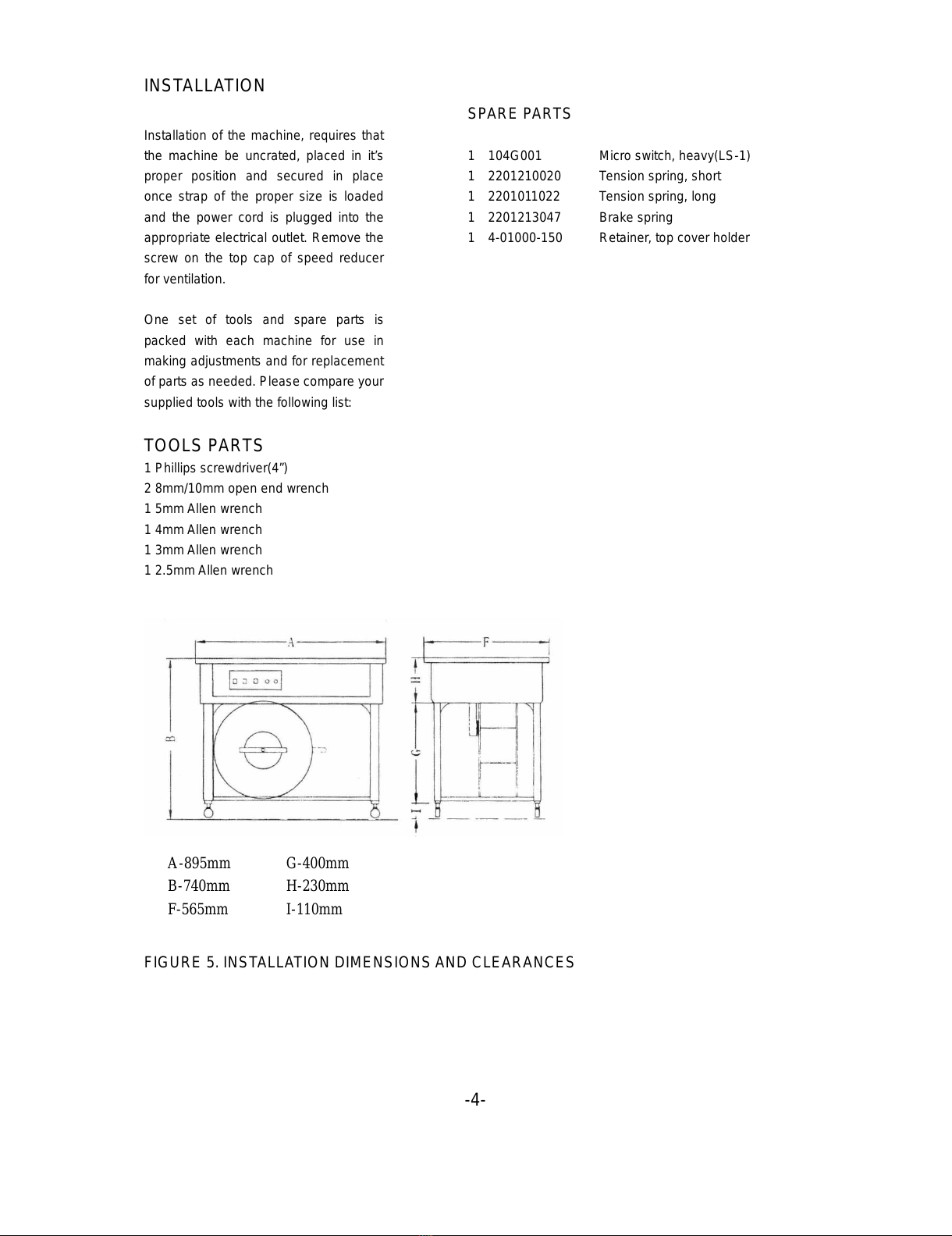
1. Open the right-hand door and pull about 3 feet (1M)of
strap from the coil.
2. Thread the strap through the looper (B), pass it under
roller (C) and allow it to exit the cabinet. Close the
right-hand door.
3. Pull up on the strap, then insert the lead-end between
the guide and roller (D).
4. Continue to push the strap through the head until it
can be seen at point (E).
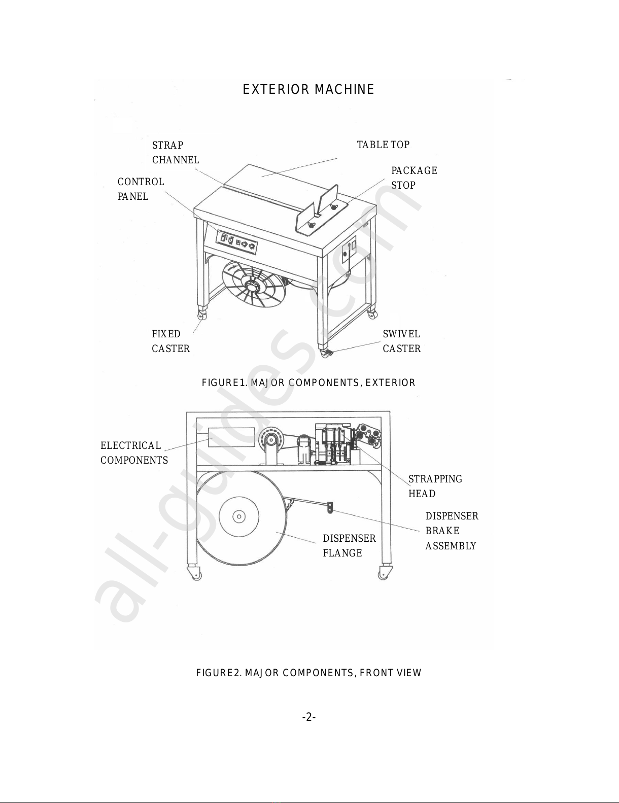
FLANGE
PLASTIC
REEL CENTER
CLAW
REEL UNT
HANDWHEEL
Y-TYPE
WASHER
FIGURE 7. DISPENSER ASSEMBLY
DISPENSER
SHAFT
PLASTIC
FLANGEA
PIN
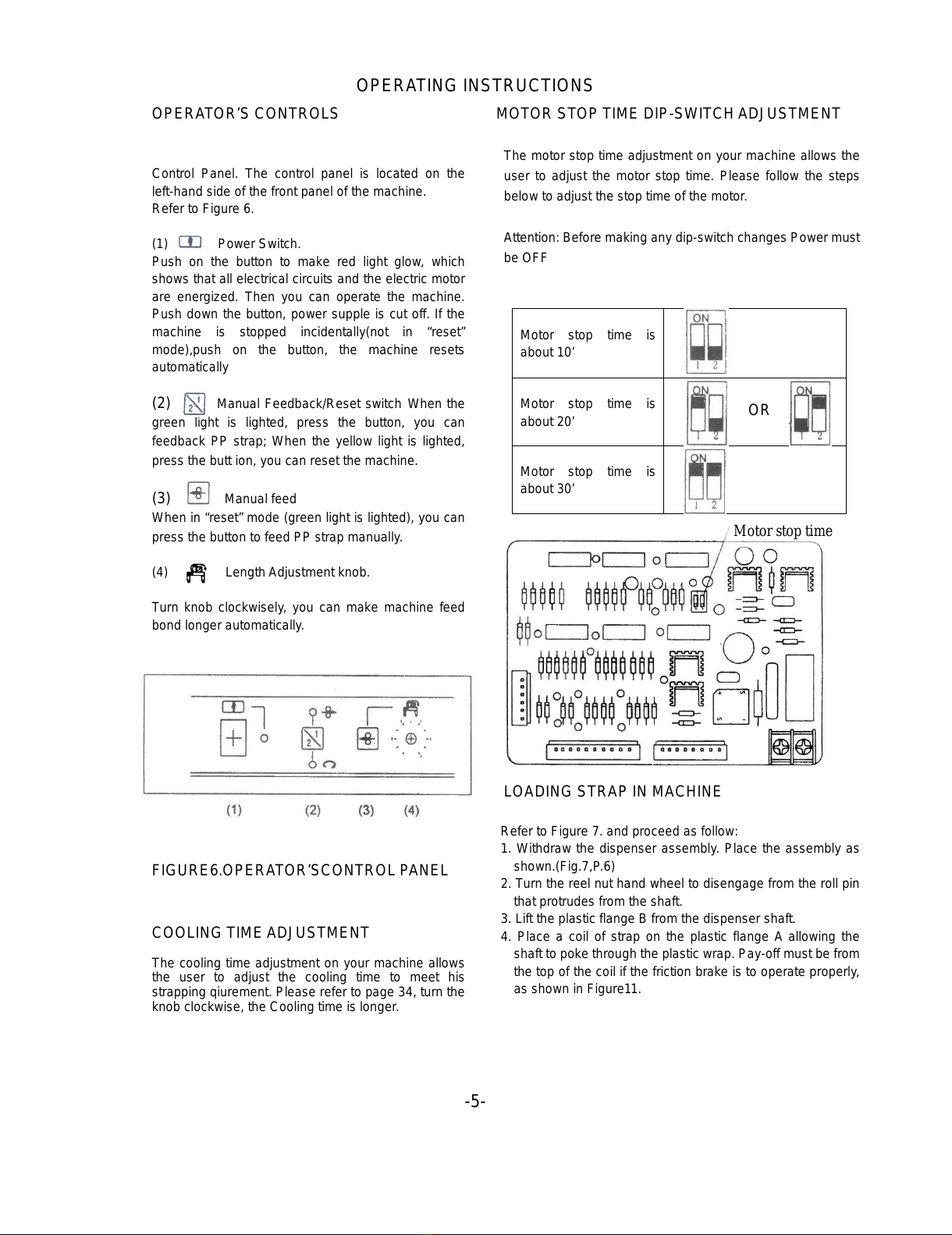
FIGURE 9. STRAP THREADING DIAGRAM
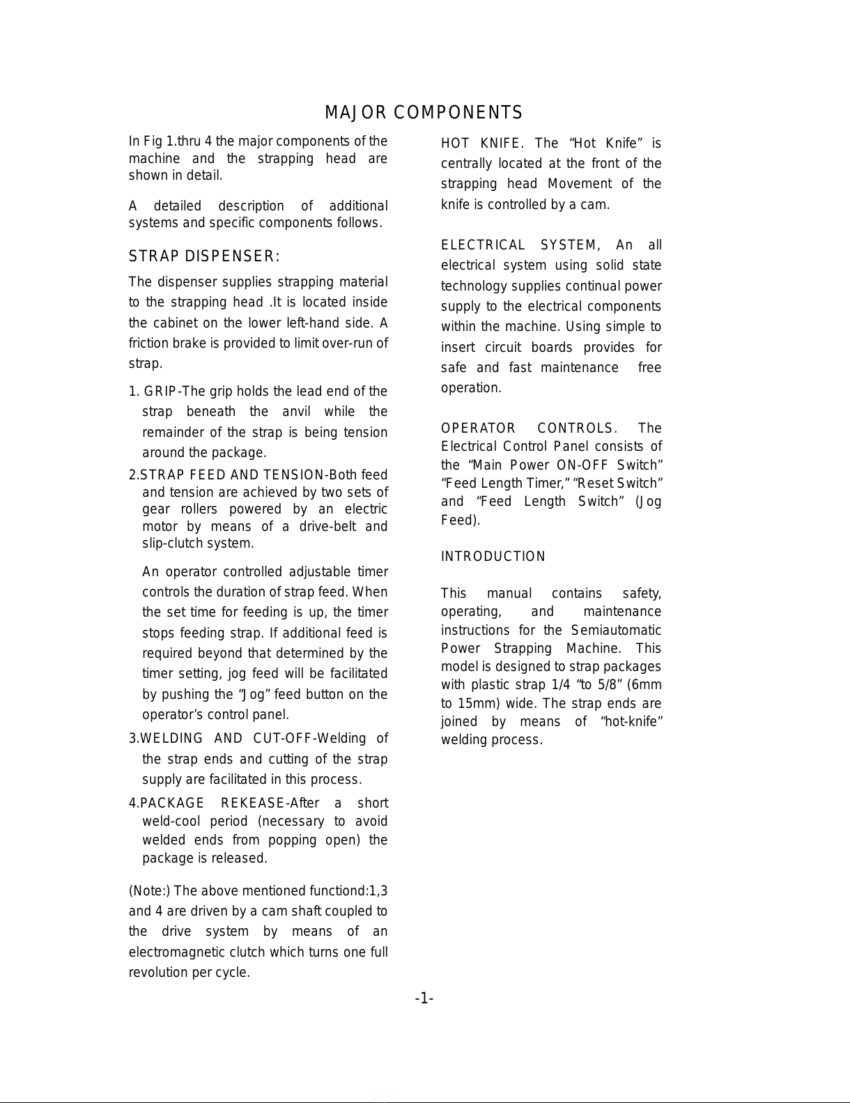
STRAPPING CYCLE
The machine is now ready for strapping a
package.
To operate the EXS-206, proceed as follow:
1. Push the power switch to the “NO” position and
allow the hot knife 5 seconds to reach operating
temperature.
2. Place a package on the table top, directly above
the sealing head. Allow the package to contact
the two package stops.
3. Grasp the strap on the left side on the package,
bring it over the package and insert the lead-end
into the strap closes LS1, the strap will be
tensioned, welded and then released, all
automatically. “CAUTION!!” Be sure to keep
fingers from beneath the strap.
Please follow instruction below to adjust the Reel center
claw (part NO. #4-07000-130) for various inner coils.
Refer to Fig. 8:
1. For 200mm inner coil diameter, position 2 holes on
the Reel center claw ( Item 6 ) to #1 and #3 holes of
the Plastic Flange A (Item 7).
2. For 230mm inner coil diameter, position 2 holes on
the Reel center claw ( Item 6 ) to #2 and #4 holes of
the Plastic Flange A (Item 7).
3. For 280mm inner coil diameter, position 2 holes on
the Reel center claw ( Item 6 ) to #3 and #5 holes of
the Plastic Flange A (Item 7).
FIGURE 8. THREADING STRAP THROUGH MACHINE
4. Remove the strapped package and note the
length of the strap fed out for the next cycle.
Adjust the time as needed.
5. Note the condition of the weld and the tension of
the tie on the package, If the condition of the weld
or the level of tension is unsatisfactory, adjust the
hot knife temperature or the tension level as
needed. Ref: Operating Adjustments.
The threading procedure involves routing strap from the
dispenser and up through the strapping head.
Refer to Figure 9 and proceed as follows: -6-
All manuals and user guides at all-guides.com

OPERATING ADJUSTMENTS
ADJUSTING TENSION
If tension adjustment is required, proceed as follows:
1. Loosen the locking knob at the right hand end of the
machine.
2. Turn the knurled knob, located at the rear of the machine,
clockwise to increase tension, counterclockwise to
decrease tension.
3. When set to the desired tension level, tighten the locking
knob.
ADJUSTING HOT-KNIFE TEMPERATURE FIGURE 10. EXIT GUIDE
If the weld appears to be only minimal, it may be that the
temperature is improperly set. Make all corrections, in
small increments, according to the following condition.
RASING HOT-KNIFE TEMPERATURE
If the weld appears to have insufficient heating, turn the
hot-knife rheostat (item 19 on the PC board), in a
clockwise direction.
LOWERING HOT-KNIFE TEMPERATURE FIGURE 11. ENTRY GUIDE
If the condition of the weld appears to have been over
heated, turn the rheostat counter clockwise.
STRAP GUIDE ADJUSTMENT TO VARIOUS
WIDTH OF P.P. STRAP
1. Strap Guide Adjustment
Loosen the Socket head cap screws (item #1 #2) and put
the upper Strap Guide against the side of Main body
block (item #8). Place p.p. strap between upper Strap
Guide (item #3 ) and lower Strap Guide (item #4) properly.
Screw those 2 Socket head cap (item #1& #2) screws
real tight.
2. Strap Guide Adjustment
Loosen the Socket head cap screws (item #1 & #2).
Place p.p. strap between strap Guide (item #5) and
Adjusting strap (item #9). Adjust item #9 to a proper room
for the p.p. strap then tighten the Socket head cap screws
(item #6 & #7).
FIGURE 12. GUIDE LOCATION
-7-
All manuals and user guides at all-guides.com
all-guides.com

PRINCIPLES OF OPERATION
GENERL 1. NEUTRAL POSITION. When the strap is
initially threaded through the machine. It
enters the head under the strap guide and
over roller D. between two sets of feed and
tension rollers and on through a slot in the
end gripper. It then passes beneath the
anvil. Over the welding clamp and holding
gripper and out into the strap channel on the
left-hand access to it,
The strapping cycle can be divided into three
distinct operations:
a. Grip and tension.
b. Weld, cut, and release.
c. Feed.
The following descriptions refer to Figures 13
through 18. Note that both the mechanical
and the control function of the micro switches
are described.
HOLDING
GRIPPER
WELDING
CLAMP END
GRIPPER
ANVIL
FEED
ROLLERS TENSION
ROLLERS
PACKAGE
STRAP
GUIDE
HOME
ROLLERD
SHAFT
ROTATION
STRAP
AT REST
FIGURE 13. NEUTRAL POSITION
-8-
All manuals and user guides at all-guides.com

2. ENCIRCLING PACKAGE; TRIPPING LS1.
Grip and tension is initiated by the operator
who encircles the package with the strap and
inserts the strap end into the slot of the upper
strap guide on the right-hand end of the
machine. In doing so, the strap is guided
between the gripper portion of the end gripper
and anvil then into a slot in the anvil where it
makes contact with the start switch detector
lever. As the lever moves to the left, it trips the
cycle start switch, LS1.
START SWITCH (LS1)
DETECTION LEVER END
GRIPPER
ANVIL UPPER
STRAP
GUIDE
PACKAGE
HOME
STRAP
AT REST
SHAFT
ROTATION
FIGURE 14. ENCIRCLING PACKAGE; TRIPPING LS1
-9-
All manuals and user guides at all-guides.com

3. TENSION. When LS1 is closed,
the electromagnetic clutch energizes and
the cam shaft rotates approximately 45
degrees. This small amount of shaft
rotation is controlled by LS3, mounted at
the right-hand end of the cam shaft.
When LS3 closes it de-energizes the
electromagnetic clutch and the end
gripper will have been moved upward to
contain the upper strap beneath the
anvil.
The tension lever pivots and closes
the tension rollers. The tension rollers
close against the strap, drawing it back
through the head, thus tensioning it
around the package. When full tension
detector reacts at same time, the
electromagnetic clutch energizes again.
LS1 DETECTION
LEVER
END
GRIPPER
TENSION
ROLLERS
TENSION
LEVERPACKAGE
ELECTROMAGNETIC
CLUTCH
END
GRIPPER
CLOSED
HOME
SHAFT
ROTATION
CAM SURFACE
LS3
CAM SURFACE
LS5
CAM SHAFT
FIGURE 15. TENSION
-10-
All manuals and user guides at all-guides.com

4. HOLDING GRIPPER RISES; HOT-KNIFE
MOVES INWARD. Momentarily electron
tension detector energizes the control circuit to
energize the electromagnetic clutch and turn
the cam shaft. As the cam shaft turns, the
holding gripper rises to contain the other end
of the strap beneath the anvil. The tension
lever is lowered to release tension and the
welding clamp begins to rise.
It’s important to note that all tension to the
strap must be released before the strap is cut,
otherwise the strap-end could be damaged
and feeding reliability will be affected. The
hot-knife moves in between the two layers of
strap.
NOTE: TENSION ROLLERS
ARE RELEASED AND STRAP
IS AT REST.
ANVIL
HOLDING
GRIPPER
HOT
KNIFE
TENSION
LEVER
WELDING
CLAMP
TENSION
ROLLERS
PACKAGE
ELECTROMAGNETIC
CLUTCH
HOME
120°
HOLDING
GRIPPER
SHAFT
ROTATION
FIGURE 16. HOLDING GRIPPER AND HOT-KNIFE
-11-
All manuals and user guides at all-guides.com

5. STRAP IS CUT; WELD IS MADE. The
welding clamp cuts the strap during it’s
upward movement then pushes the
upper surface of the lower strap
against the lower surface of the
hot-knife. It then pushes the hot-knife
the lower surface of the upper strap.
PACKAGE
WELDING
CLAMP
HOT KNIFE
HOME
135°
STRAP CUT
SHAFT
ROTATION
210°
WELD
PUSE
FIGURE 17. STRAP IS CUT & WELD IS MADE
-12-
All manuals and user guides at all-guides.com
all-guides.com

6. WELD IS RELEASED; HEAD RETURNS
TO HOME POSITION.
The hot-knife retracts and the welding clamp
pushes the two molten surfaces together,
welding the strap.
After this short delay to ensure that the strap
fuses properly, the cam shaft again turns and
the holding gripper retract to the neutral
position.
The anvil then retracts and welded strap is
released to the lower side of the package.
The cam shaft returns to the home
position and closes LS3 and LS5.
The electromagnetic clutch is
de-energized by LS3 while LS5
energizes SOL1. As the solenoid
pulls down on the tensioning lever,
the feed rollers close against the
strap, pushing it through the head
and out into the strap channel. The
feed timer de-energizes and sol1 is
released.
Strap feed stops and the machine is
ready for the next cycle.
NOTE: SOL1 ENERGIZES TO CLOSE
FEED ROLLERS AND FEED STRAP
AFTER THE CAM SHAFT REACHES
HOME POSITION.
HOLDING GRIPPER
END GRIPPER
WELDING GRIPPER
FEEDING ROLLER
ANVIL
-13-
GEAR REDUCER
SHAFT ROTATION
FIGURE 18. WELDING STRAP IS RELEASED;
HEAD IS IN HOME POSITION; STRAP FEEDS
All manuals and user guides at all-guides.com

ADJUSTMENTS CLEARANCES
Anvil to ensure that anvil operates
smoothly a minimum clearance between
the anvil and the left and right guides
must be maintained. To adjust, proceed
as follows:
VERTICAL
LOCATION OF
KEY ESTABLISHES
HEAD IN HOME
POSITION
1. Make sure the right-hand guide is
securely mounted.
2. Loosen the left-hand guide mounting
screws.
3. Insert a shim, .002” (0.50mm) thick
0..118” (3mm) wide by 5” (130mm)
long between the shoulder of the
anvil and the left guide.
4. Push the left guide against the anvil
and tighten the left guide mounting
screws.
5. Remove the shim and check to make
sure the anvil moves smoothly.
LS5
SWITCH
CLOSED
FIGURE 20. LS5
3. Position LS3 as shown in Figure 24.
When set, tighten the mounting
screws.
As the cam rotating clockwise, the
touching point of micro switch with
cam changes from B to A, then the
cooling time starts.
SWITCH CAM: The outer cam actuates
RIGHT-HAND
GUIDE
WHEN SET
CLEARANCE
.001”(0.02mm)
ON EACH SIDE
LS3. To make sure the cams are set
properly, proceed as follows:
1. Make sure the machine is in the
neutral or home position.
2. If the micro-switches need adjusting,
loosen the mounting screws and LS5
as seen in Figure 20. When properly
set, tighten the mounting screws.
WELDING CLAMP AND END GRIPPER.
To adjust the clearance between the
welding clapper and the gripper, refer to
Figure 22 and proceed as follows:
1. Remove the anvil.
2. Loosen the two socket head cap
screws that secure the “L” shaped
adjustment bracket to the casting.
ANVIL
INSERT
SHIM AT
THIS SIDE FIGURE 19. ANVIL CLEARANCE FIGURE 21.LS3
3. Push the block left or right to adjust the
clearance secure the “L” shaped
adjustment bracket to the casting.
4. When set, securely tighten the
mounting screw.
-14-
All manuals and user guides at all-guides.com

4. If there is clearance at any point,
loosen locknuts (1) and (2) and adjust all
clearance out at points A, B and C.
5. When set, tighten the locknuts.
WELDING
CLAMP
ADJUSTMENT
BRACKET
HOLDING
GRIPPER
END
GRIPPER
FEED AND TENSION ROLLERS. When
the machine is in the neutral position.
The feed and tension rollers should not
come into contact with the strap. The
clearance between the rollers should
be .040” (1.0mm). To adjust the feed
rollers away from the strap proceed as
follows:
PAETS SEEN FROM REAR SIDE HEAD
FIGURE 22. WELDING CLAMPAND GRIPPER
CLEARANCE
1. Loosen the locknuts and turn all 4
nuts upward. Make all adjustments in
very small increments. When set.
Insert a 0.202” (0.5mm) shim
between the angle plate and locknut
B and tighten locknut A against
locknut B
Note: If the cutting surface of the welding
clamp has become dull, the welding
clamp can be turned 180 degrees, thus
doubling the life of the part.
TENSION LEVER. Before making any
adjustments to the tension lever, check
to see if the tension lever is in a lever
condition. To check and adjust if need be
proceed as follows:
2. Remove the shim and press down on
the angle plate. Tighten the locknuts
C and D.
1. Manually turn the rotor of the
electromagnetic clutch until the key,
seen at the end of the end of the cam
shaft is positioned as shown in Figure
23.
To adjust the tension rollers away from
the strap reverse the above procedure.
2. Make sure the tension lever bearing is
in contact with the surface of the cam.
3. If there is no clearance at point A, B
and C then the tension lever is
considered lever..
-15-
TENSION
LEVER LOCKNUTS 1
BEARING
LOCKNUT B
LOCKNUT C
LOCKNUT D
ANGLE
PLATE
LOCKNUT A
NOTE
POSITION
OF KEY
FEED ROLLER
TENSION
RPLLER
LOCKNUTS 2
FIGURE 23. ADJUSTING TENSION LEVER
CLEARANCE BETWEEN
ROLLERS SHOULD BE
.040” (1.0mm)
FIGURE 24. ADJUSTING FEED AND TENSION
ROLLERS
INSERT .020”
(0.5mm)SHIM
AT THIS POINT
All manuals and user guides at all-guides.com

-16-
MAINTENANCE GENERAL. Periodic checks of all drive belts for
replacement should be made to prevent worn cut or
stretched belts which will affect tension.
LUBRICATION. Make sure the machine is clean
before applying lubricants to the points shown in the
figure below. Note: Use a brush or compressed air
to dispose of debris.
TENSION TRIP ARM ASSEMBLY SLEEVES.
Apply a few drops of light machine oil to the edge of
the sleeve so that the oil can penetrate to the
shoulder of the screw.
TOP SLIDE, GUIDE PLATES, WELDING CLAMP,
END GRIPPER, AND HOLDING GRIPPER.
Apply light machine oil to these parts at the point
indicated in Figure 25.
REAR REDUCE. Replace the oil in the gear
reducer once a year in the following manner:
1. Remove the lower plug and allow the oil to drain
from the gearing.
2. Reinstall the lower plug and fill with gear oil.
3. Reinstall the upper plug
FIGURE 25. LUBRICTION POINTS
WARNING
BEFORE SERVICING MACHINE
Wear safety glasses with
side shields which conform
to ANS Standard Z87.1
Failure to wear safety
glasses could result in
severe personal injury
or blindness.
PROTECT YOUR EYES
READ GENERAL SAFETY
INSTRUCTION, PAGE 2 OF
THIS MANUAL
● only trained personnel should
service machine.
● Unless specified, shut off and
disconnect all electrical power.
● Follow all service instructions.
● Make sure the hot-knife blade
is cool before servicing.
● Use the correct tools.
● Never adjust, repair or oil
moving machinery.
Note: The following parts should NEVER be
lubricated:
1. Electromagnetic clutch
2. Roller assemblies
3. Belts and pulleys
4. Clutch disc
Note: When you move the machine, you
should push it slowly.
All manuals and user guides at all-guides.com
Other manuals for EXS-206
1
Table of contents
Other Extend Packaging Equipment manuals