Stratus SAE-UT12000 Guide

Model No. SAE-UT12000
Full Rise Ultra Thin
Scissor Lift
Lifting Capacity 12000 lbs
Installation & Operation &
Maintenance Instructions
Important Note
1. This equipment can not be installed, operated or repaired without reading instructions.
2. Electricity must be hooked up by certified electrician.
3. Do not use this equipment beyond its rated capacity.


3
12000LBS Ultra-thin Scissor Lift
Contents
Chapter 1 Safety Precautions.................................................4
Chapter 2 Product and Parameters............................................5
Chapter 3 Preparation for Installation..........................................9
Chapter 4 Commissioning....................................................18
Chapter 5 Maintenance......................................................20
Chapter 6 Exploded views....................................................24

4
SAE-UT12000
Chapter 1 Safety Precautions
1. Make sure that you have read the User’s Manual completely including relevant
instructions on installation, operation and safety before operating the lift.
2. Do not use the lift if any abnormality is found in the lift.
3. Do not overload the lift beyond its rated load 3000KG.
4. The lift can be operated by trained personnel only. The vehicle customer or the
inexperienced person is prohibited from operating the lift at will.
5. The rubber pad of the small scissor lift must have contact with the support point
of the vehicle, otherwise the vehicle chassis may be damaged. (It is recommended
to consult the vehicle manufacturer by telephone if the location of the support
point is not clear.)
6. Be sure to perform mechanical locking after the vehicle is lifted. It is forbidden to
work under the vehicle before mechanical locking is performed.
7. Keep the area around the lift clean and tidy as any oil stain or obstacle may pose
a safety risk.
8. Never lift the vehicle with people in it.
9. Make sure there is no obstacle under the vehicle before lowering it.
10. It is prohibited to remove any hydraulic component when the hydraulic system
is under pressure.
11. Do not put hands at any dangerous place, such as the space between tool arms.
12. It is prohibited to use the product outdoors as it is only suitable for indoor use.
13. Press and hold the Down button while lowering, so the platforms ascend a little
automatically to open the safety lock, and then descend automatically.
14. Always wear safety shoes during operation.
15. It is forbidden to lift the vehicle when someone is in the vehicle.
16. Cut off the power supply after the use of lift.
17. When a vehicle is being loaded onto or unloaded from the lift, no person is
allowed to stand in the vehicle passage.
18. Ensure that the platforms of main and sub lifts are lowered to the lowest
positions before the vehicle departs from/leaves the lift.
19. Use wedge blocks to lock the vehicle so that the vehicle cannot move.
20. Read the operation warning label carefully and thoroughly

5
12000LBS Ultra-thin Scissor Lift
Chapter 2 Product Features and Parameters
2.1 Product features
Movable ramp which can be used as extension board
Monolithic base-plate without splice
Stable and reliable control system
Aluminum alloy motor with low noise and fast heat dissipation
2.2 Technical parameters
Rated lifting capacity
12000LBS (5500KG)
Initial height
5 4/8”(140mm)
Lifting height
74 13/16”(1900mm)
Platform length
61 7/16”--85 1/16”(1560-2160mm)
Platform width
29 4/8”(750mm)
Motor
parameters
50CBL
1PH,220VAC,3KW
Type of hydraulic oil
IS0 46#
Air pressure
0.6-0.8MPa

6
SAE-UT12000
Diagram of product:

7
12000LBS Ultra-thin Scissor Lift
Electrical diagram
8
SAE-UT12000
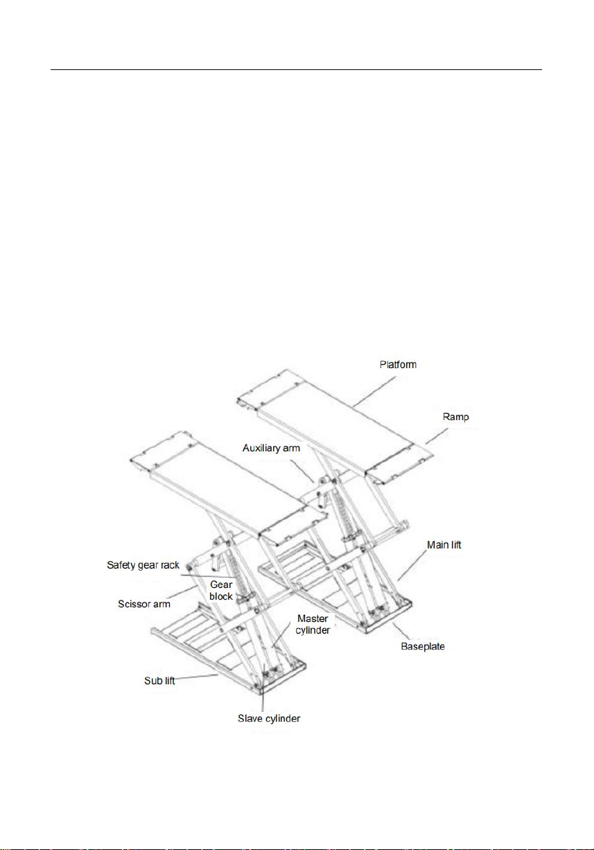
2.3 Schematic diagram for main components
Working platform: For lifting the vehicle by contacting the chassis.
Safety gear rack: Safety mechanism for mechanical locking.
Gear block: Blocking safety gear rack.
Ramp: Can be pulled up and used as extension board to bear load.
Auxiliary arm: Providing help at the start of lowering and raising.
Control cabinet: Control unit, providing the power takeoff.
Master cylinder: Actuator, pushing the platform to rise, with two oil pipes.
Slave cylinder: Actuator, pushing the platform to rise, with one oil pipe.
Scissor arm: Main lifting structure.
9
12000LBS Ultra-thin Scissor Lift
Chapter 3 Preparation for Installation
3.1 Unpacking
All packing, loading/unloading, transportation and unpacking operations must be
performed by
professional personnel.
Transportation:
The scissor lift shall be loaded/unloaded and moved by a lifting machine and
forklift with capacity over 3
tons. To prevent the scissor lift falling off, one person shall pay attention to the
scissor lift during the
lifting operation for fear of accidents. The scissor lift shall be transported by an
automobile or ship.
The scissor lift shall be inspected for completeness when it arrives, for fear of
damage or loss during
transportation.
If the packing box is broken during transportation, inspect the broken box
according to the Packing List,
confirm the damaged articles and lost components, and at the same time, inform
the carrier
immediately.
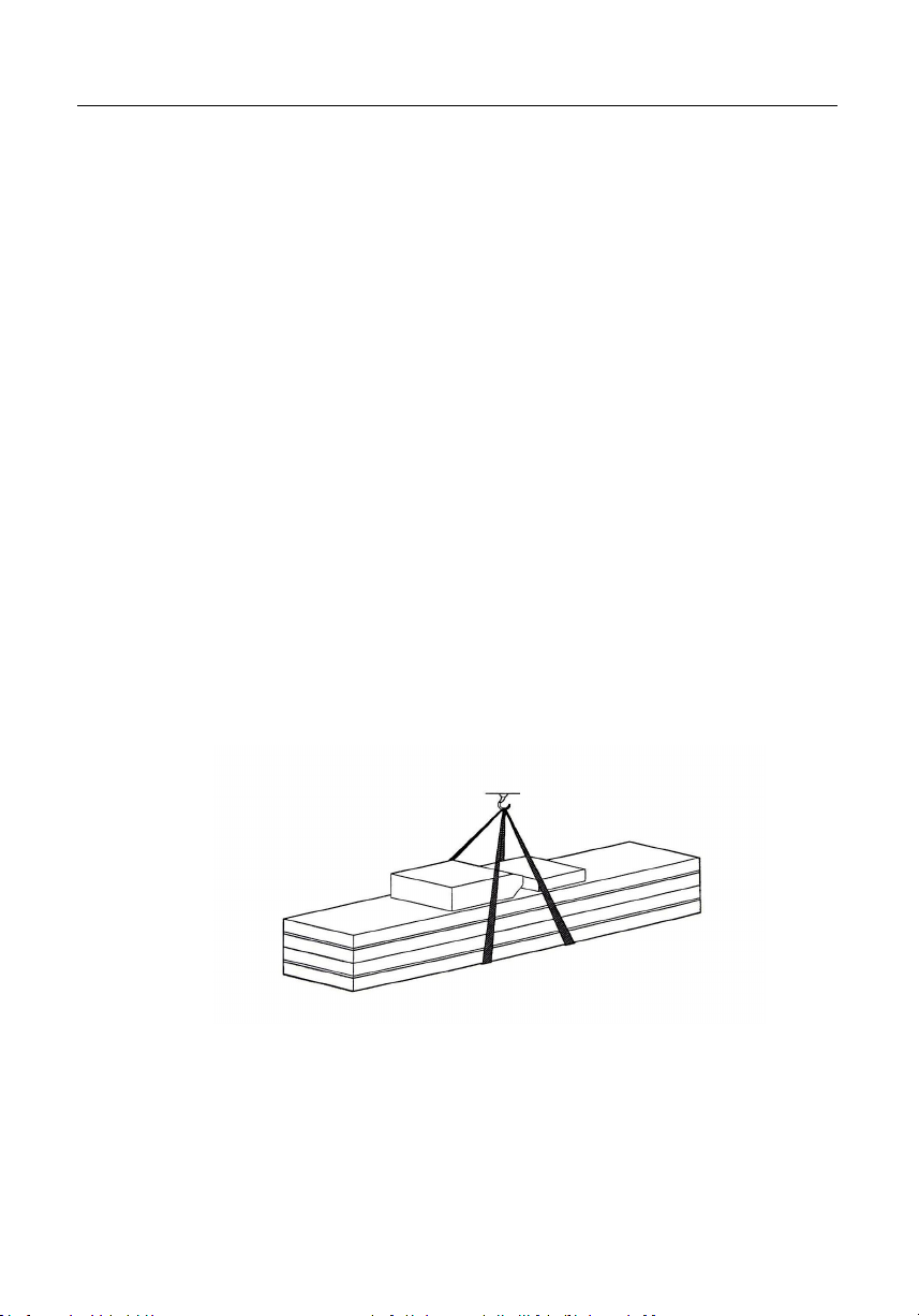
The lift is heavy! Therefore, manpower loading/unloading and handling are
forbidden. Safety is of much
importance. In addition, the hoisting of scissor lift during loading/unloading shall
be operated as
illustrated.
Storage:
Machinery equipment shall be stored in an indoor warehouse, and waterproof
treatment shall be
adopted in case of outdoor storage. A van truck shall be used for highway
transportation, and a
container for waterway transport. The control cabinet must be placed upright
during transportation, and
be protected from squeezing by other goods.

10
SAE-UT12000
3.1 Preparation for installation
Installation scheme

11
12000LBS Ultra-thin Scissor Lift
Volta
ge
Power
Start
current
Operating
current
Wire size
Air switch
Applicable to
220V
3KW
60A
21A-25A
≥4mm²
C63
Scissor lift
220V
2.2KW
60A
20A-22A
≥4mm²
C63
Two posts,four
posts
12
SAE-UT12000
3.3 Installation:
•Only professionals are allowed to conduct the installation
work. Moreover, they shall read and follow the operation
instructions below carefully to prevent machine damage or
injuries.
•Only authorized technicians are allowed to install the lift.
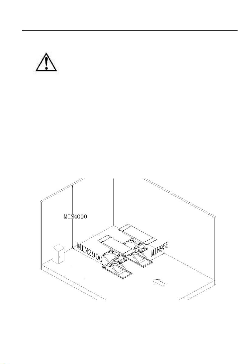
3.3.1 Installation requirements:
The lift must be installed in accordance with the specified safe distances from
walls, columns and other
equipment (as shown in Fig. 8), including the minimum distance
2000mm-2900mm from walls.
The ceiling height cannot be less than 4000mm. It is recommend to install the
lift in a pit, and construct the foundation as required in Fig. 8.
Nevertheless, the lift can be installed on any indoor floor, provided that the
floor meets the leveling requirements and has enough bearing capacity
(≧25MPa).
Fig. 8
The arrived goods shall be inspected for completeness before installation of
scissor lift.
The movement and installation of the lift shall be carried out by the
professionals.

13
For the transportation and storage of the machine, refer to the“Transportation
and Storage” on page 11.
14
12000LBS Ultra-thin Scissor Lift
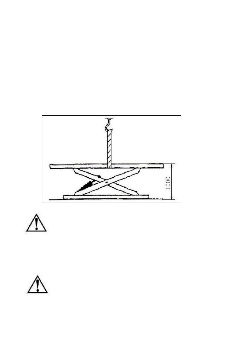
3.3.2 Installation of lifting platforms
Determine the installation direction of the lift according to the arrows
on the lift package. When the lift is
installed in the pit or on the ground, insert adjusting sizing blocks
under the platform, lift the lifting
platform with a forklift or other lifting equipment (Fig. 9) to about
1000MM, so as to ensure that the
mechanical safety device is activated and locked.
Fig.9
• To avoid the failure of the mechanical safety device, a wood block can
be inserted at the middle of the connecting rod. When the hydraulic
system is not fully filled with hydraulic oil and has the lifting and
lowering actions, do not work under the lift. Move the lifting platforms,
adjust the distance between two platforms to make them parallel, and
connect the electric circuit, oil circuit and pneumatic circuit as
specified in the Electrical Diagram and Oil Circuit Connection Diagram.
• Only after the hydraulic system connection is completed, the
pneumatic circuit connection can be conducted.
• Oil pipes, electric wires and air pipes shall not be damaged.
• Connection of electrical circuit: Connect the electrical circuit according
to the wire diameter and wire size specified in the Electrical Diagram.


14
SAE-UT12000
Only the professionals qualified for electrical operation are allowed to conduct the
electrical installation
•Open the upper cover of the control cabinet first
•Connection of power line: Connect the 380V three-phase four-wire power line
(cable of 3×2.5MM2+1×1.5 MM2) to the control cabinet interfaces U, V, W and
input terminal, and connect the PE grounding wire to the labeled grounding bolt
firstly and then to the labeled grounding bolts at the bottom of the two platforms
(Fig. 10, 11)
Fig. 10 Fig. 11
15
12000LBS Ultra-thin Scissor Lift
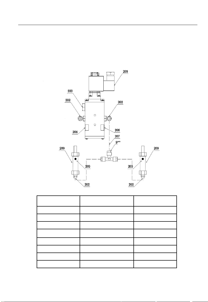
Connection schematic diagram of air pipe joint:
S/N
Part No.
Quantity
203
Muffle
3
204
Plug 1/8
1
205
Solenoid valve
1
206
Plug 1/4
1
207
Air pipe
PU0604
1
208
T-joint APE
1
209
Small cylinder
2
211
Air pipe
PU0806

16
SAE-UT12000
Schematic diagram of oil pipe joint:
Note: Adjustment is only necessary in case of imbalance of both platforms

17

18
12000LBS Ultra-thin Scissor Lift
Hydraulic schematic diagram:
Table of contents
Other Stratus Scissor Lift manuals

Popular Scissor Lift manuals by other brands


Airo
Airo X Series Use and maintenance manual

JLG
JLG 530LRT Service and maintenance manual

Custom Equipment
Custom Equipment Hy-Brid Lifts PUSH-AROUND Maintenance and troubleshooting manual

Oshkosh Corporation
Oshkosh Corporation JLG 400RTS Operation & safety manual

DINGLI
DINGLI JCPT2212DC operators manual with maintenance information

Atlas Equipment
Atlas Equipment 12ASL Installation & operation manual