1 MA_VTD410EV_A2_181015_en
Mechanics instruction
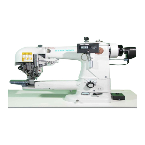
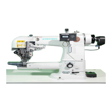
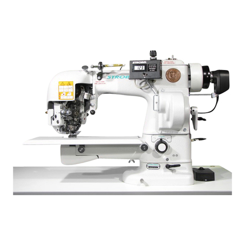
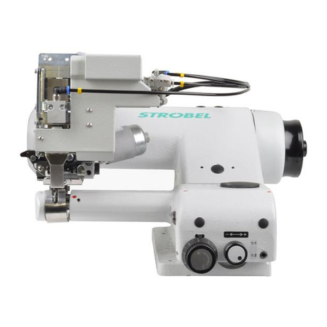
STROBEL-Class VTD410EV
Contents
1General notes on safety............................................................................................5
2General .....................................................................................................................7
2.1 Operating instructions.....................................................................................7
2.2 Class identification, serial number and orientation of the machine.................7
2.3 Range of application and intended use..........................................................7
2.4 Technical data................................................................................................8
2.5 Brief setting instructions .................................................................................9
3Hints for repair and settings ....................................................................................10
3.1 Pre-assembly................................................................................................10
3.2 Main shaft assembly.....................................................................................11
3.2.1 Removing the main shaft .................................................................11
3.2.2 Remounting the main shaft..............................................................12
3.2.3Assembly of stitch regulating eccentric............................................13
3.3 Needle bar....................................................................................................15
3.3.1 Needle adjustment...........................................................................15
3.3.2 Needle height adjustment (Fig. 5)....................................................15
3.3.3 How to adjust needle and feed motion.............................................16
3.4 Loop stroke...................................................................................................16
3.4.1 Setting the loop stroke .....................................................................16
3.5 Looper ..........................................................................................................17
3.5.1 Exchanging the looper (Fig. 6).........................................................17
3.5.2 How to set the looper shaft ..............................................................18
3.5.3 How to set looper connecting rod (Fig. 8)........................................18
3.5.4 How to mount front bearing block (Fig. 9)........................................19
3.5.5 How to mount rear bearing block.....................................................21
3.5.6 How to set the looper motion (Fig. 10).............................................22
3.5.7 How to set the looper in its front position to the rear feed cup.........23
3.5.8 Adjustment of curves (Fig. 13).........................................................23
3.6 Feed cup.......................................................................................................25
3.6.1 Removing the feed cup (Fig. 14, Fig. 15 and Fig. 16)......................25
3.6.2 Remounting the feed cup (Fig. 17)...................................................26
3.6.2.1 Chain tension...................................................................27
3.6.2.2 Mounting of pneumatically controlled shaft......................28
3.6.2.3 Front cup assembly..........................................................29
3.6.3 Height adjustment of feed cups .......................................................29
218.05.10


