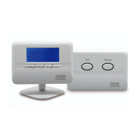
Strom SSRTEL08 User manual

STROM-
LIMITED
www.stromltd.com
RF LCD ROOM THERMOSTAT
SSRTEL08
www.stromltd.com
STROM LIMITED 2017

2DELIVERING THE POWER
STROM LIMITED
CONTENTS
USER GUIDE CONTENTS
SECTIONS PAGE
What Is A Thermostat 4
How To Use The Thermostat 5
Thermostat Button Layout 6
Thermostat Display Layout 8
Setting The Temperature 10
Locking The Temperature 10
Turning The Thermostat O (Cooling Mode Only) 10
Product Guarantee 11

3
WWW.STROMLTD.COM
STROM LIMITED
CONTENTS
INSTALLATION GUIDE CONTENTS
SECTIONS PAGE
Installation Guide 12
Thermostat & Receiver Specication 12
Read Before Installation 14
Maintenance 15
Thermostat Positioning 16
Wireless Receiver Installation 18
Wiring Diagram & Specication 20
Thermostat Commissioning & Wireless Indicator 22
Engineers Mode & Settings 24
Re-Pairing The Thermostat 28

4DELIVERING THE POWER
STROM LIMITED
WHAT IS A THERMOSTAT?
USER GUIDE
An explanation for householders:
A room thermostat is a basic mechanical or electrical switch that controls
the heating or cooling in a property. By sensing the air temperature around
it the thermostat can decide whether it should activate the heating or
cooling device that it is connected, once the requested temperature is
reached the thermostat will turn o its connected device. It is common for
a thermostat to be connected to a programmer this allows a timed pattern
to be set for the thermostat.

5
WWW.STROMLTD.COM
STROM LIMITED
HOW TO USE THE THERMOSTAT
Your thermostat does not control how quickly your home heats up
or cools down, it only controls the temperature of the property. It is
therefore recommended that after installation you set the thermostat at
a comfortable temperature and leave it set at this temperature with only
minor modication up or down throughout the year,
Increasing the temperature of the thermostat will not decrease the amount
of time required to heat the home, and will ultimately only increase fuel
costs, the same is true of cooling systems.
Normal heating systems are set usually between 18 and 21oC.
Normal cooling systems are set between 15 and 18oC.
USER GUIDE

6DELIVERING THE POWER
STROM LIMITED
THERMOSTAT BUTTON LAYOUT
USER GUIDE
Thermostat
Thermostat Display
Function Button
Battery Compartment
1
2
3
4
Selector Dial
5

7
WWW.STROMLTD.COM
STROM LIMITED
1 2
3 5
USER GUIDE
4

8DELIVERING THE POWER
STROM LIMITED
THERMOSTAT DISPLAY LAYOUT
RF Signal Indicator
Heating Or Cooling Mode (Active Mode Is Lit)
Current Room Temperature
User Set Room Temperature
Celsius Mode (Active When Lit)
Temperature Lock (Active When Lit)
Heating / Cooling Active (Active When Lit)
TPI Mode (Active When Lit)
DS Mode (Active When Lit)
Battery Life Indicator
Fahrenheit Mode (Active When Lit)
6
7
8
9
10
11
12
13
14
15
16
USER GUIDE

9
WWW.STROMLTD.COM
STROM LIMITED
6 7 8910
12 15 16
13 14
USER GUIDE
HEAT
COOL
TPI DS
11

10 DELIVERING THE POWER
STROM LIMITED
SETTING THE TEMPERATURE
Your new Strom Thermostat is extremely simple to operate. To set the
temperature simply rotate the selector dial taking note of the new set
temperature on the display .
5
9
LOCKING THE TEMPERATURE
To lock the temperature of your thermostat to prevent tampering simply
press the function button 3 times within a 2 second period, to unlock
simply repeat.
3
TURNING THE THERMOSTAT OFF - COOLING MODE ONLY
When in cooling mode your thermostat can be turned o. To turn the
thermostat o simply press and hold the function button for 5 seconds,
to turn the thermostat on simply repeat.
3
USER GUIDE

11
WWW.STROMLTD.COM
STROM LIMITED
PRODUCT GUARANTEE
USER GUIDE
Your Strom Thermostat is guaranteed by default for a period of 12 months
from the date of purchase, to redeem the parts only 3 year guarantee the
end user will need to register their unit within 45 days of purchase on our
website. The registration page can be found at :
www.stromltd.com/guarantee
The unit is only guaranteed for the 3 years if the product has been installed
and maintained in accordance with these instructions, and original proof
of purchase has been retained. We recommend keeping the installation
invoice or electricians installation certicate to prove if necessary that the
product was installed by a qualied electrician. This guarantee is a parts
only guarantee.
This guarantee specically excludes:
Damage caused by the incorrect installation or by power surges,
consequential losses - including labour charges and damages to ttings,
and any product that has not been maintained and installed in accordance
with this manual.

12 DELIVERING THE POWER
STROM LIMITED
INSTALLATION GUIDE
INSTALLATION GUIDE
The contents of this section are meant only for qualied electricians and
service engineers. Using this section of the manual without proper training
may damage your product or cause you personal injury.
Improper use of this section may render your product warrenty null and
void.
THERMOSTAT SPECIFICATION
Power Supply 2 x 1.5V AA Type Lithium Batteries
Temperature Range 10 - 30oC
Material Thermoplastic
Dimensions (HxWxD) 85mm x 88mm x 36mm

13
WWW.STROMLTD.COM
STROM LIMITED
INSTALLATION GUIDE
RECEIVER SPECIFICATION
Power Supply 90-260VAC 50/60Hz
Switch Capacity 230VAC, 6(2)A SPDT (Volt Free Contacts)
Wireless Range Approximately 30m Unobstructed
RF Frequency 868MHz
Dimensions (HxWxD) 88mm x 135mm x 35mm

14 DELIVERING THE POWER
STROM LIMITED
Instructions beyond this point are designed for qualied electricians
only, and should not be attempted by the user. Should you require any
adjustments of your controls please contact a suitable electrician.
• This unit should only be installed by a competent electrician in
accordance with all local and national regulations in force at that
time and in line with the latest IEE wiring regulations.
• This unit is for xed wiring only.
• This system must be appropriately fused using a fuse rated at no
more than 6 amps.
• Must incorperate a “Class A” switch having seperation of at least
3mm in all poles.
WARNING
IT IS ESSENTIAL THAT BEFORE ANY INSTALLATION OR
MAINTAINENCE IS CARRIED OUT THAT THE AC MAINS SUPPLY HAS
BEEN ISOLATED, FAILURE TO DO SO MAY RESULT IN DEATH.
INSTALLATION GUIDE

15
WWW.STROMLTD.COM
STROM LIMITED
Maintenance should be carried out by a qualied heating and electrical
engineer on every part of the heating and hot water system every 12
months from date of installation.
Maintenance should only be carried out after carefully reading these
instructions, and the mains AC supply disconnected before maintenance
begins.
MAINTENANCE
• We recommend a cable size of between 1.0mm2and 1.5mm2 must
be used.
• Where mounting to a metal surface, always ensure that the metal
is earthed.
• This product is not suitable for mounting on a back box.
INSTALLATION GUIDE

16 DELIVERING THE POWER
STROM LIMITED
INSTALLATION GUIDE
THERMOSTAT POSITIONING
When it comes to thermostat placement there are a few key rules to
follow to ensure your product works eciently and keeps your home warm
without wasting energy.
Do not place your thermostat next to external
doors or other sources of drafts.
Do not place your thermostat on
external walls or unusually cold
surfaces.

17
WWW.STROMLTD.COM
STROM LIMITED
INSTALLATION GUIDE
Do not place your thermostat above or immediately
next to a heat source.
1.5m Above Floor Level
Try to place your thermostat
approximately 1.5m above
ground level to get the best
reading.

18 DELIVERING THE POWER
STROM LIMITED
INSTALLATION GUIDE
WIRELESS RECEIVER INSTALLATION
1. Ensure all mains
supplies relating to the
installation are isolated.
2. Prepare the area for
the installation of the
new backplate, with
the required minimum
clearances all the way
around the backplate
and the entry point for
the wiring through the
middle of the backplate
as shown below:
100mm
100mm
40mm40mm
Cable Entry
To install your Strom Wireless Receiver simply follow the installation
procedure:

19
WWW.STROMLTD.COM
STROM LIMITED
INSTALLATION GUIDE
40mm
3. Ensure that in the suitable position that the back of the controller
once axed to the backplate is not exposed, and that the surface
is ideally non-metalic, and suitable for wall xings that will rmly
support the control and prevent accidental removal.
4. Once the suitable position has been found using a pencil mark
the xing positions on the wall, and use a suitably sized drill bit for
the wall plugs (care should be taken to ensure you are not drilling
through any utilities such as gas, water, or electric. Once drilled and
plugged secure the wall plate in position with the supplied screws.
5. Wire the backplate in accordance with the wiring diagram supplied.
6. Follow the thermostat commissioning procedure.

20 DELIVERING THE POWER
STROM LIMITED
INSTALLATION GUIDE
WIRING DIAGRAM
1 2 3N L
Neutral Live
Fused 6A
Max
COM NO NC
When wiring your backplate up, or performing maintenace on the backplate
please ensure that all the mains AC supply has been isolated.
We recommend that all wiring is done with 1.0mm2or 1.5mm2cabling, and
that care is taken to ensure good connection with the terminals.
Electrical wiring schematic
Table of contents
Other Strom Thermostat manuals
Popular Thermostat manuals by other brands
Johnson Controls
Johnson Controls T8200-TB20-9JS0/9JR0 series installation instructions
First
First DTC 200 installation instructions
oventrop
oventrop i-Tronic TFC Installation and operating instructions
Peco
Peco Performance pro T12000 quick start guide

Lennox
Lennox ComfortSense L5711U owner's guide
Continal
Continal 39003-tsrf Linking/Deleting Instructions
