Salus HTRP230V User manual

HTRP230V(50) THERMOSTAT - FULL USER MANUAL


TABLE OF CONTENTS
1. Introduction...............................................................................................................................................................4
1.1 Product Compliance ......................................................................................................................................................................4
1.2 Safety Informations.......................................................................................................................................................................4
1.3 Product Overview..........................................................................................................................................................................5
2. Montage ....................................................................................................................................................................6
2.1 Package content............................................................................................................................................................................6
2.2 Proper thermostat location ...........................................................................................................................................................6
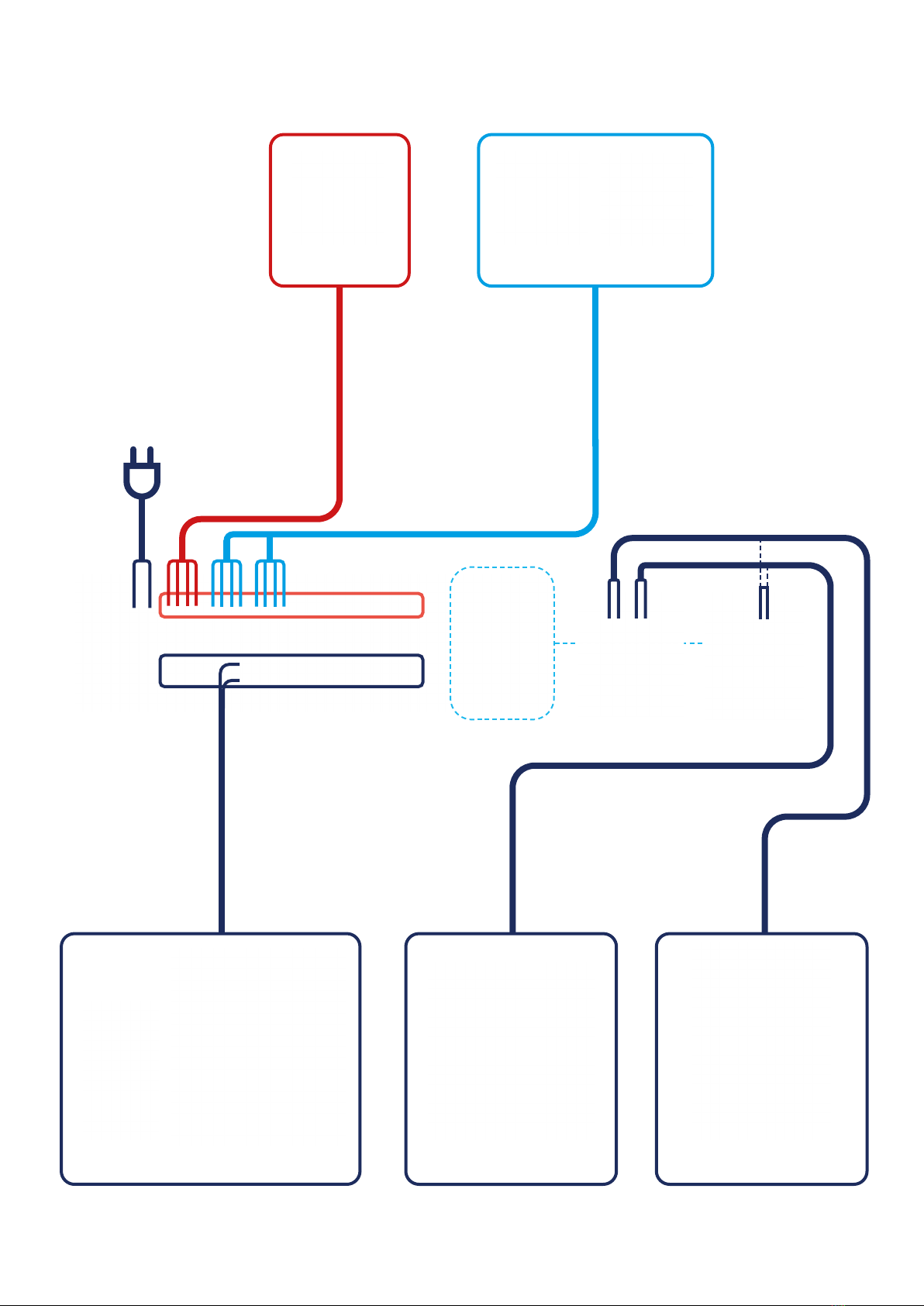
2.3 Connection description..................................................................................................................................................................7
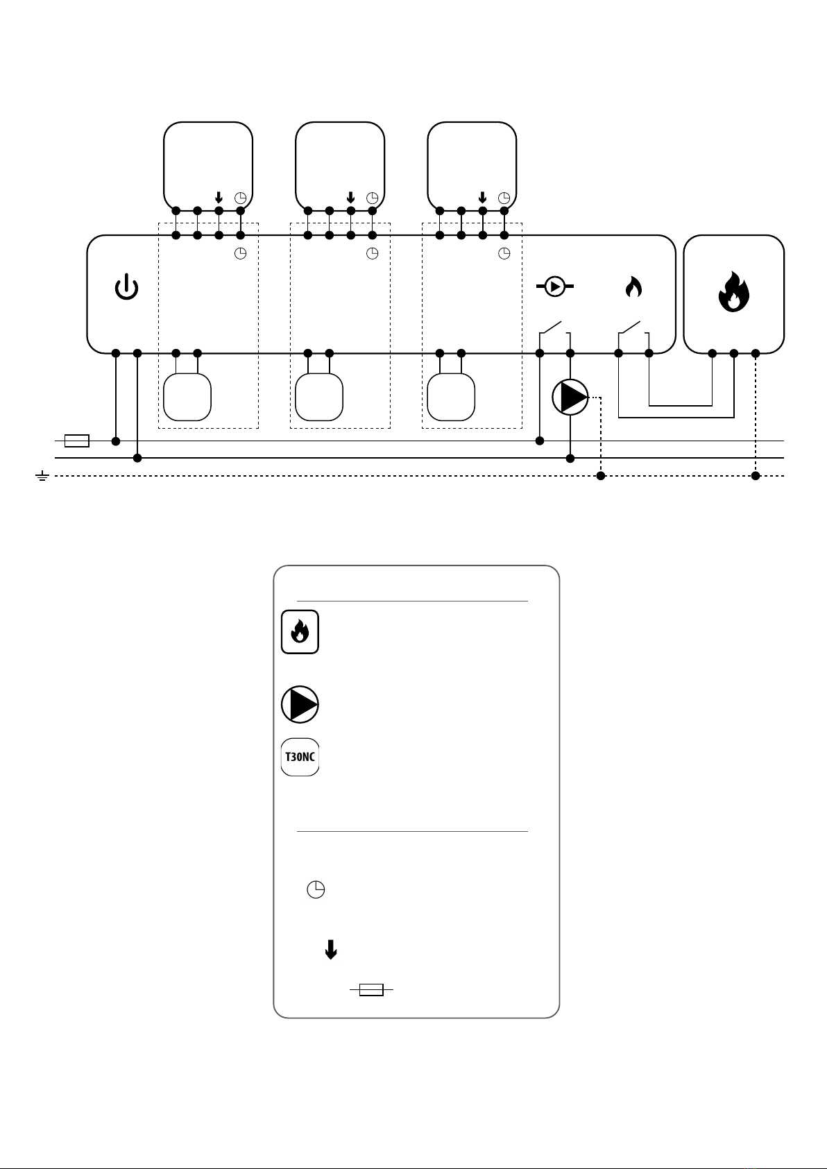
I A - 4 wire installation with KL08NSB wiring centre.............................................................................................................8
I B - 4 wire installation with KL06 wiring centre.................................................................................................................10
II - 3 wire installation with KL08NSB wiring centre ............................................................................................................12
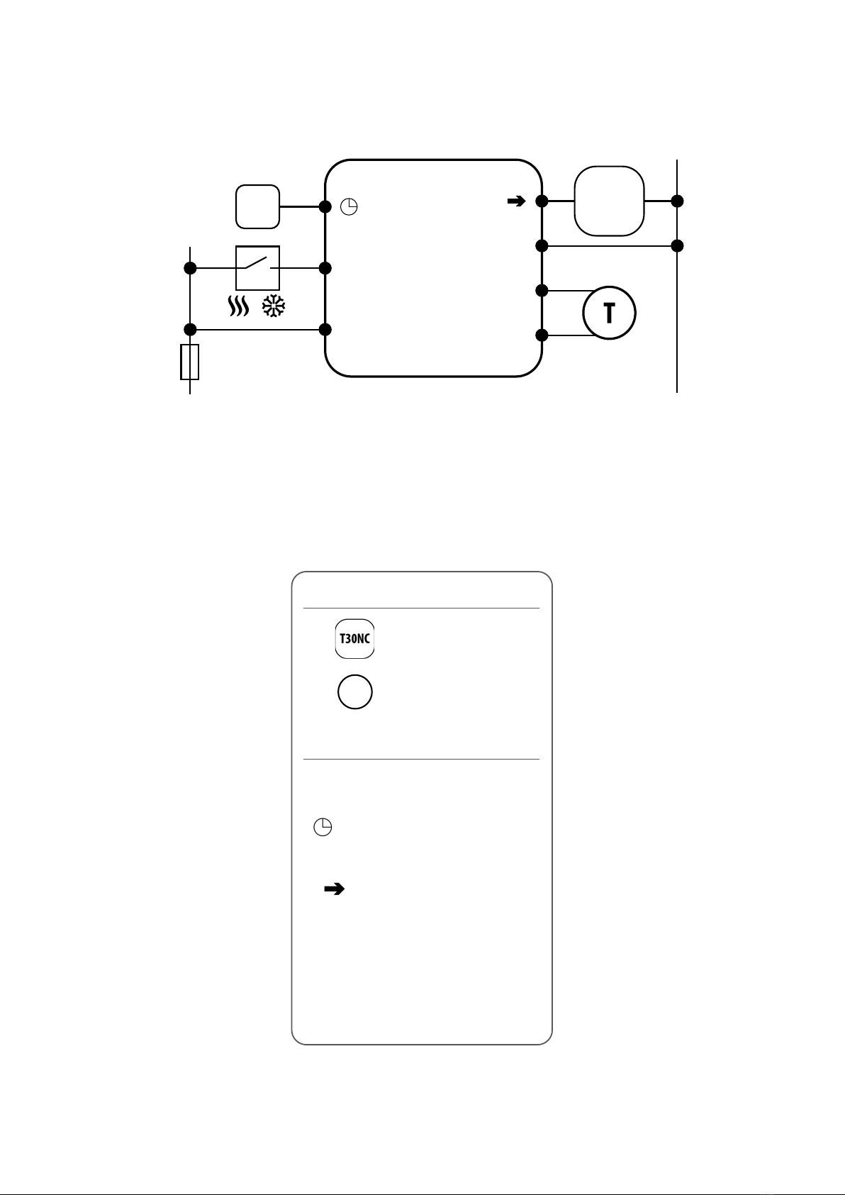
III A - work with RM-16A relay module - volt-free heating source control..........................................................................14
III B - work with RM-16A relay module - connecting an electrical device with a higher power..........................................15
3. Before you start (rst power up) ................................................................................................................................16
3.1 LCD icon description ....................................................................................................................................................................16
3.2 Button description.......................................................................................................................................................................16
3.3 First power up sequence..............................................................................................................................................................17
4. Work modes..............................................................................................................................................................18
5. User settings (basic settings) .....................................................................................................................................19
5.1 Schedule mode - programming schedule....................................................................................................................................19
5.2Time/Date ...................................................................................................................................................................................22
5.3 Thermostat calibration ................................................................................................................................................................23
5.4 Heat/cool mode change..............................................................................................................................................................24
6. Installer parameters .................................................................................................................................................25
7. Factory Reset............................................................................................................................................................27
8. Cleaning and Maintenance ........................................................................................................................................28
9. Technical Informations..............................................................................................................................................28
10. Warranty................................................................................................................................................................28

4
This product complies with the essential requirements and other relevant provisions of Directives 2014/53/EU and 2011/65/EU. The full text of the EU
Declaration of Conformity is available at the following internet address: www.saluslegal.com.
• Before starting installation work and before using the product, read the entire manual.
•The information contained in the instructions is essential for proper functioning.
•To avoid accidents resulting in personal injury and material damage, please follow all safety precautions, specied in this manual.
• The device should not be used by people with limited mental, sensory or mental abilities, without experience, of insucient knowledge as well as
children.
• Do not use an unassembled device (eg without a cover).
•The device may only be opened by a qualied person.
• Keep electrical devices out of the reach of children and ensure that they do not play with it. Children should not be left unattended. If necessary,
disconnect the control system for the entire room.
• Do not leave the packaging, cabinet, or any loose parts of the device unattended, as they pose a risk to children.
WARNING!
• Installation must be carried out by a qualied person with appropriate electrical qualications in accordance with standards and regulations in force in
the given country and in the EU.
• Never try to connect the device other than as described in the manual.
• Before assembly, repair or maintenance as well as during any connection works it is absolutely necessary disconnect the mains supply and make sure
that the terminals and electric wires are not live.
•The device may not be exposed to extreme temperatures, strong vibrations or subjected to mechanical shock.
• The device should not be used in unfavorable environmental conditions or in rooms where there is a concentration of ammable gases, fumes or dust.
WARNING!
•There may be additional protection requirements for the entire installation that the installer is responsible for maintaining.
1. Introduction
1.1 Product Compliance
1.2 Safety Informations
Care for the natural environment is of paramount importance to us.The awareness that we manufacture electronic devices obliges us
to dispose of used electronic components and devices safely.Therefore the company has received a registration number issued by the
ChiefInspectorfor EnvironmentalProtection.The crossed out symbolthe trashcan onthe product meansthat the product must notbe
disposed of with ordinary waste containers. Sorting waste for recycling helps to protect the environment. It is the user’s responsibility
to surrender used equipment to a designated collection point for recycling waste from electrical and electronic equipment.

5
The HTRP230V(50) from SALUS Controls is a stylish and accurate 5/2 or 24h programmable electronic thermostat with a large, easy to read Liquid Crystal
Display (LCD). It is surface-mounted temperature controller dedicated for surface heating / cooling, characterized by high thermal inertia. It is connected
to the wired wiring centre KL08NSB. Thermostat has the function of creating your own schedules. It can control group (SLAVE) thermostats - via wiring
centre it sends them an NSB (nighttime temperature reduction) signal and switches them to economic temperature. The time schedule is common to all
thermostats (according to weekly (MASTER) thermostat), but temperatures are set individually on each thermostat.
The programmable room thermostat HTRP230V(50) is both a programmer and a room thermostat. A programmer allows you to set‘ON’and‘OFF’time
periodsto suit yourownlifestyle.A room thermostatworksbysensing the airtemperature,switching on theheatingwhen theair temperature fallsbelow
the thermostat setting and switching it o once this set temperature has been reached.
So, a programmable room thermostat lets you choose what times you want the heating to be on, and what temperature it should reach while it is on.
It will allow you to select dierent temperatures in your home at dierent times of the day (and days of the week) to meet your particular needs.
Turning a programmable room thermostat to a higher setting will not make the room heat up any faster. How quickly the room heats up depends on the
design of the heating system, for example, the size of boiler. Neither does the setting aect how quickly the room cools down. Turning a programmable
room thermostat to a lower setting will result in the room being controlled at a lower temperature, and saves energy.
The way to set and use your programmable room thermostat is to nd the lowest temperature settings that you are comfortable with at the dierent
times you have chosen, and then leave it alone to do its job.The best way to do this is to set low temperatures rst, say 18°C, and then turn them up by one
degree each day until you are comfortable with the temperatures.You won’t have to adjust the thermostat further. Any adjustments above these settings
will waste energy and cost you more money.
PRODUCT ADVANTAGES:
• absolutely silent operation (TRIAC)
• has a PWM control algorithm
• protection against too high or too low temperature using an additional FS300 oor sensor
• protection of thermostatic valves against stagnation (VP)
• an input for the additional temperature sensor
• has frost protection mode
1.3 Product Overview

6
2. Montage
2.1 Package content
1) HTRP230V(50) thermostat
2) Short instruction
3) Mounting screws
2.2 Proper thermostat location
Please note:
Wall mounting
Mounting: to mount thermostat you can use accesories included with the set (mounting screws). Remove back cover to mount the plate to the wall.
Now please insert the batteries inside the thermostat. After this just attach thermostat to the plate right into designed holes in the plate.
The ideal position to thermostat mounting is about 1,5m under oor level far from heating or cooling sources.
Thermostat can’t be exposed to sunlight or any extreme conditions like for example draft.
Because of re and explosion risk there is not allowed to use thermostat in atmosphere of explosive gases and ammable liquids (eg coal dust). In case
if any of listed dangers occur you have to use additional protection measures – anti-dust and explosive gases (tight cover) or prevent their formation.
Furthermore, thermostat can’t be used in condensation of water vapor conditions and be exposed to water action.
12
3
Open the housing with a screwdriver - as shown in the pictures above.
Without an additional
temperature sensor.
With an additional
temperature sensor.

7
L, N - power supply 230V
- NSB - Night temperature reduction
(230V output)
-SL - 230V AC output signal
CO - Switching jumper between heating and
cooling (input 230V AC)
S1, N - additional temperature sensor
eg. FS300
2.3 Connection description
HTRP 230 KL08 NSB
L
S1
N
N
CO
L
SL
N
HTRP 230
Wejście NSB
w regulatorze SLAVE
L
N
S1
N
CO
L
AC 230V
N
T30NC
Wyjście NSB
/
NSB input in
SLAVE thermostat
NSB output
Legend:
Thermal actuator
Temperature sensor
Symbols explanation:
T

8
THB23030 PUMP (optional)T30NC230 BOILER
4 wires x 0.75 mm
4 wires x 0.75 mm
Power Supply
230V AC
Actuators wires
2 x 0.75 mm Pump control wires
2 x 1 mm Boiler control wires
2 x 1 mm
KL08NSB KL04NSB (optional)
SLAVEMASTER
HTRP230(50) HTRS230(30) HTR230(20)
I A - 4 wire installation with KL08NSB wiring centre
When HTRP230V(50) thermostat works as a MASTER (group controller) it means it takes control of SLAVE thermostats e.g. HTRS230V(30), HTR230V(20).
MASTER thermostat controls SLAVE thermostat only when SLAVE thermostat is in AUTO mode. Comfort (SUN) and economy (MOON) setpoint
temperatures are set individually on each thermostat but switching between those temperature is based on time schedule taken from HTRP230(50)
thermostat which works like a group controller. Functions such as: setpoint temperature change, holiday mode, party mode or frost protection mode are
not managed by MASTER thermostat.

9
SLAVEMASTER
L
AC 230V
L
N
N
1 - 8 Strefy 1 - 8 Strefy 1 - 8 Strefy
KL08NSB
Pump BoilerPower
L N
SL
T30NC
L N
SL
T30NC
L N
SL
T30NC
lu ub
VS30 RT200 RT520
L L L
L
or or
L
1 2 BOILER CONNECTION*
1-8 Zones1-8 Zones1-8 Zones
3 4
N N N
N N
N
L
max 6
per zone max 6
per zone max 6
per zone
HTRP230V(50) HTRS230V(30) HTR230V(20)
L, N - power supply 230V
- NSB - Night temperature reduction
(230V output)
-SL - 230V AC output signal
- fuse
Legend:
Symbols explanation:
Thermal actuator
Pump
Boiler - Boiler connection* - Boiler’s
contacts for ON/OFF thermostat
(according to the boiler’s instructions)

10
I B - 4 wire installation with KL06 wiring centre
THB23030T30NC230
Power Supply
230V AC
Actuators wires
2 x 0.75 mm Pump control wires
2 x 1 mm Boiler control wires
2 x 1 mm
KL06 PL07 PL06
PUMP (optional) BOILER
4 wires x 0.75 mm
4 wires x 0.75 mm
SLAVEMASTER
HTRP230(50) HTRS230(30) HTR230(20)

11
L, N - power supply 230V
- NSB - night temperature reduction
(230V output)
-SL - 230V AC output signal
NC, NO - voltage-free output
- fuse
Legend:
Symbols explanation:
Thermal actuator
Pump logic module (for KL06) connection diagram
Pump and boiler logic module (for KL06) connection diagram
Pump
Boiler - Boiler connection* - Boiler’s
contacts for ON/OFF thermostat
(according to the boiler’s instructions)
PL07
PODŁĄCZENIE KOTŁA*
L
1
2
3
4
AC 230V lub 24V
N
MAX
5 (2) A
or
BOILER CONNECTION*
NC
NO
PL06
PODŁĄCZENIE KOTŁA*
NC
NO
PL06
L N
MAX
5 (2) A
AC 230V lub 24V
or
BOILER CONNECTION*
L
AC 230V
L
N
N
1 - 6 Strefy
KL06-M
Power
L N
L N
T30NC max 6
na strefę
RT10 // RT20
Np. Np.
L N
1 - 6 Strefy
PL06
L N
L N
T30NC max 6
na strefę
RT520
COM NO
lub
NC
NO
PODŁĄCZENIE KOTŁA*
L
AC 230V
L
N
N
1 - 6 Strefy
KL06-M
Power
L N
L N
T30NC max 6
na strefę
RT10 // RT20
Np. Np.
L N
1 - 6 Strefy PL06
L N
L N
T30NC max 6
na strefę
RT520
COM NO
lub
NC
NO
L N
MAX
5 (2) A
AC 230V lub 24V
L
AC 230V
L
N
N
1 - 6 Strefy
KL06-M
Power
L N
L N
T30NC max 6
na strefę
RT10 // RT20
Np.
Np.
L N
1 - 6 Strefy PL06
L N
L N
T30NC max 6
na strefę
RT520
COM NO
lub
NC
NO
PODŁĄCZENIE KOTŁA*
L
AC 230V
L
N
N
1 - 6 Strefy
KL06-M
Power
L N
L N
T30NC max 6
na strefę
RT10 // RT20
Np. Np.
L N
1 - 6 Strefy PL06
L N
L N
T30NC max 6
na strefę
RT520
COM NO
lub
NC
NO
L N
MAX
5 (2) A
AC 230V lub 24V
or or
BOILER CONNECTION*
1-8 Zones1-8 Zones1-8 Zones
max 6
per zone max 6
per zone max 6
per zone
HTRP230V(50) HTRS230V(30) HTR230V(20)
L L LN N N
SLAVEMASTER

12
II - 3 wire installation with KL08NSB wiring centre
3 wire installation with KL08NSB wiring center. Description of the operation rules:
- HTRP230V(50) thermostat’s functionality is limited because of 3 wire installation. NSB function is disabled and HTRP230V(50) thermostat doesnt work
as a MASTER thermostat - no eect on other thermostats like HTRS230V(30) or HTR230V(20)
- schedules can be set individually on each HTRP230V(50) thermostats if system is equipped with more than one HTRP230V(50) thermostat
PLEASE NOTE!
The same operating rules apply to wiring center KL06.
THB23030 PUMP (optional)T30NC230 BOILER
3 wires x 0.75 mm
3 wires x 0.75 mm
Power Supply
230V AC
Actuators wires
2 x 0.75 mm Pump control wires
2 x 1 mm Boiler control wires
2 x 1 mm
KL08NSB KL04NSB (optional)
HTRP230(50) HTRP230(50) HTRP230(50)

13
L
AC 230V
L
N
N
1 - 8 Strefy 1 - 8 Strefy 1 - 8 Strefy
KL08NSB
Pump BoilerPower
L N
SL
T30NC
L N
SL
T30NC
L N
SL
T30NC
lu ub
VS30 RT200 RT520
L L L
L
or or
L
1 2 BOILER CONNECTION*
1-8 Zones1-8 Zones1-8 Zones
3 4
N N N
N N
N
L
max 6
per zone max 6
per zone max 6
per zone
HTRP230V(50) HTRP230V(50) HTRP230V(50)
L, N - power supply 230V
- NSB - Night temperature reduction
(230V output)
-SL - 230V AC output signal
- fuse
Legend:
Symbols explanation:
Thermal actuator
Pump
Boiler - Boiler connection* - Boiler’s
contacts for ON/OFF thermostat
(according to the boiler’s instructions)

14
III A - work with RM-16A relay module - volt-free heating source control
RM-16A
L
AC 230V
N
L
AC 230V
N
L
AC 230V
N
L
AC 230V
N
NO
NO
COM
COM
(wejście)
(wejście)
(wejście)
(wejście)
NOCOM
NOCOM
NC
SL
L N SL
N
L
PODŁĄCZENIE KOTŁA*
VS30
Np.
RT520
Np.
RM-16A
MAX
16 (5) A
RM-16A
NO
NO
COM
COM
NC
SL
L N SL
N
L
VS30
Np.
NOCOM
091FL
Np.
NO
COM
NC
SL
N
L
PODŁĄCZENIE KOTŁA*
STAŁOPALNEGO
T30NC T30NC
RM-16A
NO
NO
COM
COM
NC
SL
N
L
L N
1 - 8 Strefy
KL08NSB
Power
L N
L N SL
MAX
16 (5) A
Connection of a 230V AC voltage thermostat to a boiler
(or other device) with an ON - OFF contact.
HTRP230V(50)
BOILER CONNECTION*
(input)
L, N - power supply 230V
-SL - 230V AC output signal
NO, COM, NC - voltage-free output
- fuse
Legend:
Symbols explanation:
Boiler - Boiler connection* - Boiler’s
contacts for ON/OFF thermostat
(according to the boiler’s instructions)

15
RM-16A
L
AC 230V
N
L
AC 230V
N
L
AC 230V
N
L
AC 230V
N
NO
NO
COM
COM
(wejście)
(wejście)
(wejście)
(wejście)
NOCOM
NOCOM
NC
SL
L N SL
N
L
PODŁĄCZENIE KOTŁA*
VS30
Np.
RT520
Np.
RM-16A
MAX
16 (5) A
RM-16A
NO
NO
COM
COM
NC
SL
L N SL
N
L
VS30
Np.
NOCOM
091FL
Np.
NO
COM
NC
SL
N
L
PODŁĄCZENIE KOTŁA*
STAŁOPALNEGO
T30NC T30NC
RM-16A
NO
NO
COM
COM
NC
SL
N
L
L N
1 - 8 Strefy
KL08NSB
Power
L N
L N SL
MAX
16 (5) A
(input)
HTRP230V(50)
III B - work with RM-16A relay module - connecting an electrical device with a higher power than the thermostat relay allows
PLEASE NOTE! The maximum current consumption of an electrical device should not exceed 16A.
L, N - power supply 230V
-SL - 230V AC output signal
NO, COM, NC - voltage-free output
- fuse
Legend:
Symbols explanation:
Pump
Valve actuator
Heating mat

16
OR
1. Increase or decrease setpoint temperature.
2. Increase or decrease Day, Clock,Timer, Party and Holiday.
3. Select installer parameter value.
1. Long press to return to home display without saving.
2. Short press to return to the previous screen when it is in user/installer
setting mode.
Mode selection.
1. OK key: Short press to conrm selection.
2. Long press to save and exit.
3.When Main Screen – long press to enter the user settings.
+
Hold down these buttons for 3 SECONDS to enter installer parameter settings.
Button Function
3. Before you start (rst power up)
Button Description
3.2 Button description
3.1 LCD icon description
1. Comfort temperature
2. Economic temperature
3. Automatic mode
4. PARTY mode
5. Holiday mode
6. Frost protection mode
7.Temperature unit
8. Heating mode ON
9. Cooling mode ON
10. External temperature sensor
11. Manual mode / override temp.
12. Current / set temperature
13. AM / PM
14. Day indicator
15. Clock
16. Program number
16
15
11121314
7
8
9
10
1 2 3 4 5 6
PLEASE NOTE!The LCD screen can be activated by using any button.
OR

17
3.3 First power up sequence
After that, thermostat will automatically power
up and start boot sequence and it will display
all icons...
Conrm by button.
Set date (year, month and day) using
„ ” or „ ”buttons.
Conrm by button.
After all, the main screen will be
displayed.
Set time format „ ” or „ ”buttons.
Conrm by button.
Set time (hours and minutes) using
„ ” or „ ”buttons.
Conrm by button.
...then thermostat will display the
software version.
Remove the protection foil, remove back
cover by using at-blade screwdriver.
Connect the thermostat to 230V power
supply, referring to the connection
description in chapter 2.3.
2
1
4 5 6
3
7 8

18
4. Work modes
Use or buttons to switch
between work modes .
1 2
43
Use or buttons set
temperature setpoint.
Conrm by button. Thermostat will go back to the main
screen after saving the settings.
HTRP230V(50) oers 6 work modes. Frame on a given icon indicates which mode is currently active. In manual mode only one temperature level is
maintained (2 types of pre-dened setpoint temperature for manual mode ).Thermostat follows programmed schedule when AUTO mode is active („A”
icon). Party mode is an hour extension of the comfort temperature mode. Holiday mode activates frost protection mode for a given number of days. Last
mode is Frost Protection (snowake icon) - setpoint temperature of the frost protection mode can be changed only in the Installer parameters (please
look at the chapter 6, parameter D08).
- Frame - means that the work mode is active (the icon of the work mode must be in the center of the frame). For example:
- means that comfort temperature mode is active
- means that comfort temperature mode is inactive
Example - comfort temperature mode setpoint editing:
- Comfort temperature mode - pre-dened setpoint temperature. Usually set when we are indoors. The highest maintained temperature in
heating mode or the lowest if thermostat works in the cooling system. Acting alone works as a manual mode. Temperature range: from 5°C to 35°C.
- Economic temperature mode - pre-dened setpoint temperature. Usually set at night or when we are out of the house. Acting alone works as a
manual mode.Temperature range: from 5°C to 35°C.
- Automatic mode temperature (schedule) - follows programmed schedule. Schedule can be temporarily override with new setpoint
temperature (temporary override mode will be active to the next change forced by schedule, hand icon will be displayed).
- Party mode - this mode sets the comfort temperature for a user-dened time (maximum 9 hours 50 minutes).
- Holiday mode - this mode sets the frost protection mode for a user-dened time (maximum 99 days).
- Frost protection mode - usually used during extended periods of absence or during the holidays (only available in heating mode). Temperature
range: from 5°C to 17°C.
3

19
5. User settings (basic settings)
5.1 Schedule mode - programming schedule
To program schedule, please follow steps below:
There are 4 possible schedule variants. Use and buttons to select schedule variant and conrm by button:
Separate schedule for WORKING DAYS. Separate schedule for WEEKENDS.
One schedule for
WHOLE WEEK
Seven separate schedules for
SINGLE DAYS
1 2
3
Enter into the schedule settings.
Hold button for 3 seconds to
enter the menu.
3 sec.

20
Select schedule variant by
button. Use or buttons to set hour.
Conrm by button.
Use or buttons to set
minutes. Conrm by button.
Repeat steps 5 and 9 for the next time periods
in the schedule to set whole program for
selected variant. No time --:-- on the display
means given program is skipped.There are
6 programs/time periods in the schedule.
Hold button for 3 seconds to save and exit
schedule editing.
To run the schedule (activate thermostat’s automatic mode), use and buttons to move the frame to the„A”icon.
Schedule programming example for the WORKING DAYS variant:
10
45 6
8 97
Use and buttons to choose
comfort or economic setpoint
temperature.
Schedule editing will jump to the
next program’s time setting.
Set time for selected mode using
or buttons again.
Conrm by button.
Conrm by button.
1 2
3
3
This manual suits for next models
1
Table of contents
Other Salus Thermostat manuals

Salus
Salus Optima S User manual

Salus
Salus SOLO ST920WF User manual

Salus
Salus RT200 User manual

Salus
Salus Quantum WQ610 User manual

Salus
Salus QUANTUM SQ610RF User manual

Salus
Salus RT510LG5V User manual

Salus
Salus HTRP230 User guide

Salus
Salus HTRS-RF (30) User manual

Salus
Salus AWRT10RF User manual

Salus
Salus VS05 User manual
Popular Thermostat manuals by other brands

Smeco
Smeco CoolSentry Quick reference guide

Atag
Atag One zone WIT-AAONEW0Z manual

Bryant
Bryant PREFERRED T6-PRH owner's manual

1 Source
1 Source S1-TBEU22P7S installation instructions

meitav-tec
meitav-tec ETN24-SUPER-SH-F Owner's manual & technnician settings

White Rodgers
White Rodgers 1F97W-51 installation instructions