manuals.online logo
Brands
  1. Home
  2. •
  3. Brands
  4. •
  5. Stromberg Carlson Products
  6. •
  7. Ladder
  8. •
  9. Stromberg Carlson Products LA-401 User manual

Stromberg Carlson Products LA-401 User manual

StrombergCarlson.com • 231.947.8600
11"
7"
12"
8.5"
12"
12" Safest Design
can add 15"
additional length,
however, not
recommended.
12"
12"
12"
12"
Roof Mount
92.5"
5"
CL to CL
INS-LA401LA401BA 11.20.2020
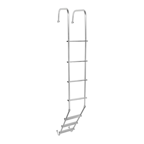
Universal Exterior RV Ladder
Model: LA-401, LA-401BA
Universal Exterior RV Ladder LA-401, LA-401BA
Thank you for purchasing the Stromberg Carlson Universal Exterior
RV Ladder.
Read these directions thoroughly before assembly. When assembled
and used properly, this ladder will provide many years of trouble
free service. This kit contains components and hardware for one
complete exterior ladder. Complete the following easy steps and
you will be ready to use your new ladder.
Tools Needed for Installation
#2 Phillips screwdriver
Hack saw or tube cutter
Drill
3/16” and 1/4” drill bit
Masking tape or pencil
Adjustable wrench or pliers
6
1
Carton Contents and Assembly Diagram
PART # MODEL # DESCRIPTION QTY
1LA-401-A1 Top U-Shape Ladder Section 2
(1LA-401BA-A1)
1LA-401-A2 Middle Straight Ladder Section 1
(1LA-401BA-A2)
1LA-401-A3 Bottom J-Shape Ladder Section 1
(1LA-401BA-A3)
8535 5” Standoff Assemblies 4
(8535-B)
8525-BK Swivel Castings (hinges) 2
8521-BK Roof Mount Brackets 2
(8521-BK-B)
1LA-401-B #10 Sheet Metal Screws 28
#10-24 x 30 mm Bolts and Nuts 6
#10-24 x 37 mm Bolts and Nuts 2
1
2
3
4
5
7
6
2
3
4
5
4
CAUTION: All screws connecting the ladder to the RV must
be fastened to the RV’s blocking or sub frame. If you are
unsure about the structure location, contact your trailer
manufacturer. It is unsafe to use a ladder that is not connected
to the RV’s blocking or sub frame. Maintain safe contact with
your new ladder at all times while ascending or descending.
Be sure to use an outdoor type sealant at all points where holes
are drilled into your RV.
Maximum weight capacity – 250 lb when properly installed.
Universal Exterior RV Ladder LA-401, LA-401BA
StrombergCarlson.com • 231.947.8600
5. Attach (2) Roof Mount Brackets (Part 6) through the holes at
the end of the upright tubes, using (2) #10-24 x 37 mm bolts
(Part 7).
6. Attach the Roof Mount Brackets to the roof of your RV, using
(4) #10 Sheet Metal Screws (Part 7). Be sure to anchor them
into backing/framing.
7. Attach the top (2) 5” Standoff Assemblies (Part 4) to your RV,
using (8) #10 Sheet Metal Screws (Part 7). Be sure to attach
where your RV ladder and the backing/framing locations
coincide. You can turn the standoff mounting plate to best
align with the structural backing in your RV. These standoffs
should meet your ladder uprights between the top two
treads.
8. Mark your ladder uprights where the standoffs meet. Drill
1/4” holes through your ladder uprights and attach the
standoffs, using the bolts that were stored in the cap of the
standoff.
9. Place the rectangular mounting plates from the Bottom
J-Shape Ladder Section (Part 3) against your RV (where
backing/framing exists), approximately 6” to 12” above your
bumper, in line with the ladder sections already installed.
FIGURE 1
5"
Trim as
necessary
10. Keeping 5” spacing between the ladder and the rear wall of
your RV, mark the ladder tubing where the Bottom J-Shape
and Middle Straight Ladder Sections meet. Trim excess
ladder tubing, using a hacksaw or tube cutter. See Figure 2
FIGURE 2
Trim at
intersection
1. Determine backing/framing locations in the rear wall and
roof of your RV and mark with masking tape or a pencil.
This will help you determine standoff placement later in
the installation. If you are unable to locate backing/framing
with a stud finder or other method, you can call your RV
manufacturer for a blueprint or contact an RV service center.
2. Insert the (2) Top U-Shape Ladder Sections (Part 1) into the
Middle Straight Ladder Section (Part 2). Bolt them together
using (2) #10-24 x 30 mm bolts (Part 7).
3. Keeping the Middle Straight Ladder Section parallel with
the back wall of your RV, place the ends of the Top U-Shape
Ladder Sections on the roof of your RV. Be sure to maintain
5” spacing between the vertical tube and back wall of your
RV for installation of the standoffs in later steps.
4. Trim the roof mount ends of the Top U-Shape Ladder Section
vertical tubes so the ladder will mount flush to the roof
(trimming may not be necessary). If you trim off the pre-
drilled holes, you will need to drill 3/16” holes, 1/2” up from
the bottom of the newly cut tube. See Figure 1 11. For RVs with a flat rear wall, turn the (2) Swivel Castings
(Part 5) so they swivel left and right when facing the ladder
and insert them in the Middle Straight and Bottom J-Shape
Ladder Sections. Inserting the Swivel Castings like this will
keep the ladder from flexing toward or away from your
RV. Drill a 3/16” hole through the ladder tubing and Swivel
Casting 1/2” above and 1/2” below the trimmed ladder
end. Connect the ladder tubing and Swivel Castings using
(4) #10-24 x 30 mm bolts (Part 7).
12. For RVs with a curved rear wall, turn the (2) Swivel Castings
(Part 5) so they swivel toward and away from you when
facing the ladder and insert them in the Middle Straight
and Bottom J-Shape Ladder Sections. Inserting the Swivel
Castings like this will allow the ladder to follow the curve
of your RV. Drill a 3/16” hole through the ladder tubing and
Swivel Casting 1/2” above and 1/2” below the trimmed
ladder end. Connect the ladder tubing and Swivel Castings
using (4) #10-24 x 30 mm bolts (Part 7).
13. Use (8) #10 Sheet Metal Screws (Part 7) to attach the Bottom
J-Shape Ladder Section brackets to your RV backing.
14. Attach the bottom (2) 5” Standoff Assemblies (Part 4) to
your RV, using (8) #10 Sheet Metal Screws (Part 7). Be sure
to attach where your RV ladder and the backing/framing
locations coincide. You can turn the standoff mounting plate
to best align with the structural backing in your RV. These
standoffs should meet your ladder uprights 8”-10” below
your Swivel Castings.
15. Mark your ladder uprights where the standoffs meet. Drill
1/4” holes through your ladder uprights and attach the
standoffs, using the bolts that were stored in the cap of the
standoff.
16. Make sure all hardware is tight and the ladder is secured
through structural backing/framing prior to use. For safety
purposes, check ladder integrity prior to each use.

This manual suits for next models

7

Other Stromberg Carlson Products Ladder manuals

Stromberg Carlson Products LA-2021460 User manual

Stromberg Carlson Products

Stromberg Carlson Products LA-2021460 User manual

Stromberg Carlson Products LA-460 User manual

Stromberg Carlson Products

Stromberg Carlson Products LA-460 User manual

Stromberg Carlson Products LA-401 User manual

Stromberg Carlson Products

Stromberg Carlson Products LA-401 User manual

Stromberg Carlson Products LA-2022152 User manual

Stromberg Carlson Products

Stromberg Carlson Products LA-2022152 User manual

Stromberg Carlson Products LA-401 User manual

Stromberg Carlson Products

Stromberg Carlson Products LA-401 User manual

Popular Ladder manuals by other brands

POP UP MI TOWER STAIRS Assembly guide

POP UP

POP UP MI TOWER STAIRS Assembly guide

AGI Westeel Wide-Corr Installation and Storage Instructions

AGI

AGI Westeel Wide-Corr Installation and Storage Instructions

Draper TL11/A instructions

Draper

Draper TL11/A instructions

Marchetti CLASS02 quick start guide

Marchetti

Marchetti CLASS02 quick start guide

wibe 808030 Assembly instruction

wibe

wibe 808030 Assembly instruction

Euro Towers THE PODFATHER Assembly instructions

Euro Towers

Euro Towers THE PODFATHER Assembly instructions

Würth Scale instructions

Würth

Würth Scale instructions

Realtree RTLS-503 Instruction & safety manual

Realtree

Realtree RTLS-503 Instruction & safety manual

zarges Z200 Assembly and use instructions

zarges

zarges Z200 Assembly and use instructions

zarges Skymaste Industrial Z600 manual

zarges

zarges Skymaste Industrial Z600 manual

Fiamma DELUXE SPRINTER Installation and usage instructions

Fiamma

Fiamma DELUXE SPRINTER Installation and usage instructions

Xtend+Climb HOME 750P PLUS Operational and care instructions

Xtend+Climb

Xtend+Climb HOME 750P PLUS Operational and care instructions

HOMCOM B72-035 manual

HOMCOM

HOMCOM B72-035 manual

SSC MidMade LUX A1120 Assembly instructions

SSC

SSC MidMade LUX A1120 Assembly instructions

Alice's Garden Vega manual

Alice's Garden

Alice's Garden Vega manual

Confer Plastics CCX-IG Assembly and installation manual

Confer Plastics

Confer Plastics CCX-IG Assembly and installation manual

Roto Columbus installation manual

Roto

Roto Columbus installation manual

Power Gear Kwikee Troubleshooting Flowchart

Power Gear

Power Gear Kwikee Troubleshooting Flowchart

manuals.online logo
manuals.online logoBrands
  • About & Mission
  • Contact us
  • Privacy Policy
  • Terms and Conditions

Copyright 2025 Manuals.Online. All Rights Reserved.