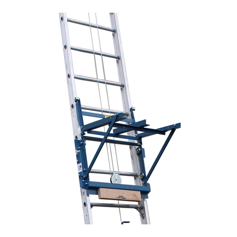
Little Giant Ladder 13 Assembly instructions

3
Little Giant Ladder System®Manual
TABLE OF CONTENTS
Little Giant Ladder System
Description - Little Giant Ladder System® . . . . . . . . . . . . . . . . . . . . . . . . 4
Operating and Adjusting Ladders . . . . . . . . . . . . . . . . . . . . . . . . . . . . . . . 5
The Hinge . . . . . . . . . . . . . . . . . . . . . . . . . . . . . . . . . . . . . . . . . . . . . . 5
The Lock Tab Assemblies . . . . . . . . . . . . . . . . . . . . . . . . . . . . . . . . . . . 6
The A-frame Position . . . . . . . . . . . . . . . . . . . . . . . . . . . . . . . . . . . . . . 7
The Extension Position . . . . . . . . . . . . . . . . . . . . . . . . . . . . . . . . . . . . . 8
The Staircase Position . . . . . . . . . . . . . . . . . . . . . . . . . . . . . . . . . . . . . 8
Scaffolding Trestle Operation Instructions . . . . . . . . . . . . . . . . . . . . . . . 9
Work Platform Operation Instructions . . . . . . . . . . . . . . . . . . . . . . . . . 10
The Wheels . . . . . . . . . . . . . . . . . . . . . . . . . . . . . . . . . . . . . . . . . . . . . 12
Final Cautions and Warnings . . . . . . . . . . . . . . . . . . . . . . . . . . . . . . . . 12
Maintenance . . . . . . . . . . . . . . . . . . . . . . . . . . . . . . . . . . . . . . . . . . . . . . . 14
Replacement Parts . . . . . . . . . . . . . . . . . . . . . . . . . . . . . . . . . . . . . . . . . . 15
Family Safety
Family Safety Bulletin . . . . . . . . . . . . . . . . . . . . . . . . . . . . . . . . . . . . . . . . 17
Little Giant SkyScraper
Description - Little Giant SkyScraper . . . . . . . . . . . . . . . . . . . . . . . . . . . . 22
Operating and Adjusting the ladder . . . . . . . . . . . . . . . . . . . . . . . . . . . . . . 23
The Hinge . . . . . . . . . . . . . . . . . . . . . . . . . . . . . . . . . . . . . . . . . . . . . . 24
The Lock Assembly . . . . . . . . . . . . . . . . . . . . . . . . . . . . . . . . . . . . . . . 24
Adjusting the A-frame ladder . . . . . . . . . . . . . . . . . . . . . . . . . . . . . . . . 25
Adjusting the staircase ladder . . . . . . . . . . . . . . . . . . . . . . . . . . . . . . . 26
Other Little Giant Products
The Little Giant® Accessories . . . . . . . . . . . . . . . . . . . . . . . . . . . . . . . . . . 27
The Little Jumbo® Safety Step . . . . . . . . . . . . . . . . . . . . . . . . . . . . . . . . . 29
The Little Giant® Ultra Step . . . . . . . . . . . . . . . . . . . . . . . . . . . . . . . . . . 30
Warranty Statement . . . . . . . . . . . . . . . . . . . . . . . . . . . . . . . . . . . . . . . . . 31
LITTLE GIANT LADDER SYSTEMS®one ladder does it all!™ www.littlegiantladders.com

4
I. Description - Little Giant Ladder System®
A. Multifunctional Ladder Unit - comprised of three basic components - an inner
ladder unit assembly and two outer unit assemblies which telescope over the inner.
1. The inner ladder assembly has 2 locking center hinges which allow the entire
ladder system to be used in the following configurations:
a. A-frame
b. Extension
c. Stairwell
d. Scaffolding trestles
e. Storage
2. Locking mechanisms on the two outer assemblies of the ladder permit the
outer telescoping sections of the ladder to be adjusted in length. This lock tab
assembly fits in any rung of the inner ladder, allowing foot-by-foot adjustment
on either end of the ladder.
B. Model Specification Table
C. The inner and outer side rails are made of aircraft grade aluminum.
1. There are slip-resistant aluminum rungs on both inner and outer assemblies.
2. Both inner and outer assemblies are finished with slip-resistant feet.
Model
Model 13
Model 17
Model 22
Model 26
Storage
3’7”
4’7”
5’7”
6’7”
A-Frame
3’0” to 5’0”
4’0” to 7’0”
5’0” to 9’0”
6’0” to 11’0”
Extension
7’0” to 11’0”
9’0” to 15’0”
11’0” to 19’0”
13’0” to 23’0”
Operating Instructions for Little Giant Ladder System®
CAUTION: SCAFFOLDING TRESTLE CONFIGURATION ONLY TO BE
USED WITH OPTIONAL WORK PLATFORM SPREADER ATTACHMENT.
WARNING: INSPECT UPON RECEIPT AND BEFORE EACH USE. NEVER
USE A DAMAGED OR BROKEN LADDER.

CAUTION: In all applications, except for transporting the ladder, the
wheels must not have contact with the ground. Do Not use wheels as step.
II. Operating and Adjusting The Ladder
A. The Hinge - located at the top of the ladder when it is in storage position, per-
mits you to alter the shape of the ladder. The hinge locks in the following positions
(See Figures A-1, A-2, and A-3).
1. Unlock the hinge by pushing straight in on the Palm Button until it stays in
the open (unlocked) position on both hinges (See Figures A-4 and A-5).
a. NOTE - If there is pressure on hinge lock pins it will be difficult to
unlock the hinge. To relieve pressure, simply adjust one half of the ladder
back and forth until hinge lock pins move without force.
5
Figure A-4
LOCKED
Figure A-5
UNLOCKED
Palm
Button
Hinge
Lock
Pins
Figure A-1 Figure A-2 Figure A-3
IF EQUIPPED WITH WHEELS

6
b. NOTE - DO NOT FORCE HINGE
LOCK in or out with any tools as it will
cause permanent damage to the hinge
mechanism. It should never require
more than light pressure to unlock the
hinge if the holes are properly aligned.
2. You may now open the ladder to the
A-frame position by pulling the two ladder
halves apart until both hinge lock pins snap
into the A-frame locked position.
3. Now place the ladder into the extension
position by again pushing straight in on
the palm buttons of both hinges (See Figures
A-4 and A-5).
Rotate either side of the ladder until the
hinge locks snap into their locked position.
To restore the ladder to the storage position,
reverse the above procedure. The hinge
lock will lock automatically at the A-frame
configuration to prevent damage to the
ladder or injury to the user.
Use caution and do not let the full weight
of the ladder fall on the hinge lock as the
ladder folds from extension to A-frame
configuration. Disengage the hinge locks in
the A-frame position and return the ladder
to its storage position.
B. The Lock Tab Assemblies- The second
mechanical component of the ladder system is
the LOCK TAB ASSEMBLY. There are four of
these on each ladder. These permit you to change
the height of the ladder (See figure B-1 and C-1).
Hinge
Figure C-1
Figure B-1
Lock Tab Assemblies
CAUTION: HEED THE WARNING IMPRINTED
ON THE HINGE! “HINGE LOCK MUST BE
FULLY IN BEFORE USING, FAILURE TO DO
SO MAY RESULT IN INJURY”

7
C. Adjusting the height of the ladder for use in the A-frame position.
1. Unlock both hinge locks (See figures A-4 & A-5).
2. With the ladder in the storage position and while holding the inner ladder
assembly firmly in place, pull the four Lock Tab Assemblies out of the rung holes
of the inner ladder and rest them on the side of the outer ladder rail (See
figures C-1).
3. Raise the inner ladder up to the desired height.
4. At the desired height align the outer holes with the nearest rung hole of the
inner ladder assembly.
5. Holding the inner and outer ladder at the aligned height with one hand, rein-
sert the opposite Lock Tab Assemblies into the rung holes with the other hand.
6. Alternate hands and perform the same operation with the other Lock Tab
Assemblies (See figure C-2).
7. Open the ladder to the A-frame configuration by pulling the ladder halves
apart until the hinges lock into place (See figure A-2 and A-4).
8. To return the ladder to the storage position, reverse the procedures and posi-
tion as seen in Figure A-1.
Figure C-2
WARNING: LOCK TAB ASSEMBLIES MUST BE INSERTED INTO AN
INNER LADDER ASSEMBLY RUNG HOLE. FAILURE TO DO SO MAY
RESULT IN INJURY.
CAUTION: HEED THE WARNING ABOVE EACH LOCK ASSEMBLY
WARNING: DO NOT PULL OUT ALL FOUR
LOCK TAB ASSEMBLIES UNLESS THE
INNER LADDER ASSEMBLY IS PREVENTED
FROM SLIDING DOWN.
WARNING: WHEN TELESCOPING THE
INNER LADDER WITHIN THE OUTER BASES,
NEVER ALLOW CLOTHING OR BODY PARTS
TO BE PLACED BETWEEN THE RUNGS.
ALWAYS HOLD THE LADDER WITH BOTH
HANDS ON THE VERTICAL UPPER RAILS
OR HINGES OF THE LADDER WHILE TELE-
SCOPING UP OR DOWN.

8
D. Adjusting the height of the ladder in its exten-
sion ladder position.
1. From its stored position, unlock hinge (as indi-
cated in figures A-4 & A-5) and rotate to exten-
sion position until both hinges lock into place.
NOTE: Hinge will first lock in A-frame position,
repeat unlocking hinge to rotate its extension
position.
2. If equipped with wheels, wheels must be
at the top of the ladder while in the extention
position. Unlock Lock Tab Assemblies on upper
half of the ladder. Grasp the outer ladder, walk
backward, allowing the ladder to telescope to the
desired height. If more height is desired, extend
the lower half of the ladder (see figure D-1).
3. To store the ladder from its extension posi-
tion, reverse the above sequence starting with the
lower half of the ladder.
E. Staircase Position.
1. Adjust ladder to desired height (review sec-
tion concerning adjusting the height of the ladder
for use in the A-frame position.) If equipped
with wheels, the wheels should be placed on the
bottom of the long side, not against the stairs.
2. Then adjust the side desired for proper
alignment to fit the staircase (see figure E-1).
WARNING: DO NOT REMOVE LOCK TAB
ASSEMBLIES FROM LOWER HALF OF THE
LADDER WITHOUT HAVING A SECURE HOLD
ON THE INNER SECTION.
Figure E-1
WARNING: WHEN TELESCOPING THE
INNER LADDER WITHIN THE OUTER BASES,
NEVER ALLOW CLOTHING OR BODY PARTS
TO BE PLACED BETWEEN THE RUNGS.
ALWAYS HOLD THE LADDER WITH BOTH
HANDS ON THE VERTICAL UPPER RAILS
OR HINGES OF THE LADDER WHILE TELE-
SCOPING UP OR DOWN.
Figure D-1A
DO NOT
Figure D-1
WHEELS
AT TOP
WHEELS
AT
BOTTOM

Figure F-5
Close
9
F. Scaffolding Trestle Operating Instructions
(Does not apply to Little Giant® Fiberglass ladder)
1. Pull the inner ladder assembly completely
out of the outer ladder bases (see figure F-1).
2. Open the inner ladder assembly to the
A-frame position until both hinges lock (See
figures A-4 and A-5). This is the first of two
trestles needed for the scaffolding function
(see figure F-2).
3. Grasp both outer ladder bases (see
figure F-3).
4. If equipped with wheels, turn ladder with-
out wheels 180º and insert lock assemblies of
that base into the adjacent holes of the oppo-
site outer base (see figure F-4). Wheels should
be facing out (see figure F-5).
5. Grasp the outer ladder base with the unused
lock assemblies and lower 1/2 inch, then spread
the opposite outer ladder base to form a second
A-frame trestle (see figure F-5 and F-5 Close).
6. Rotate forked ears on work platform
to position indicated in figure F-6.
7. Insert work platform between outer ladder
bases on the third rung down of each base. The
wire-formed end of the work platform should
surround the outer rung turned to the inside of
the outer ladder A-frame trestle
(see figure F-7).
Figure F-5
CAUTION: SCAFFOLDING TRESTLE
CONFIGURATION ONLY TO BE USED WITH
OPTIONAL WORK PLATFORM SPREADER
ATTACHMENT.
Wheels should
not be on inside
of trestle
Figure F-1
Figure F-2
Figure F-3
Figure F-4
Figure F-7
Figure F-6
Doing this step
incorrectly may
cause damage
to ladder.

8. Press down on top of work platform until it locks in a horizontal position. Outer
ladder A-frame trestle is now ready for use as second trestle (see figure F-8).
9. Space the two trestles and place an appropriate scaffolding plank on the set of
rungs at the desired working height (see figure F-9).
G. Work Platform Operating Instructions
1. Tighten or loosen bolts until brackets move stiffly (see figure G-1).
2. Adjust to fit ladder rung (see figure G-2).
3. Place platform at desired height (see figure G-3).
4. Push platform forward and step up through the rung above platform
(see figure G-4).
10
Figure F-8 Figure F-9
WARNING: MAKE CERTAIN WORK PLATFORM IS
LOCKED INTO POSITION BEFORE CLIMBING, WING
ENTERPRISES INC. ASSUMES NO LIABILITY FOR
DAMAGE OR INJURY WHICH MAY RESULT BY FAILING
TO FOLLOW ALL INSTRUCTIONS CORRECTLY.
CAUTION: HEED THE WARNING LABEL PLACED ON THE OUTER
LADDER HALF REGARDING THE USE OF THE WORK PLATFORM AS A
SPREADER ATTACHMENT.

11
Figure G-3 Figure G-4 Figure G-5
Figure G-6 Figure G-7 Figure G-8
5. Push platform back with toe (see figure G-5) until the forward tip of the
platform rests against the rung.
6. Check to ensure platform is securely in place before putting full weight on it
(see figure G-6).
7. When through, step to rung above work platform and push work platform
forward with toe. Step down through work platform (see figure G-7).
8. The above instructions apply to the A-frame ladder also. The platform may
also be used as a utility shelf (see figure G-8).
CAUTION: HEED THE
WARNING LABEL
PLACED ON THE WORK
PLATFORM.

12
H. Wheels
1. Hold ladder with wheels
towards you. Tip ladder onto
wheels. Hold the top rung and
pull the ladder behind you.
I. Final Cautions And Warning
1. When adjusting hinges or
Lock Tab Assemblies, keep
body parts and clothing out of the working mechanisms. These mechanisms are
constructed of heavy duty materials and can pinch if carelessly adjusted.
2. When telescoping the inner ladder within the outer bases, never allow clothing
or body parts to be placed between the rungs. Always hold the ladder with both
hands on the vertical upper rails or hinges of the ladder while telescoping up or
down.
3. When using ladders around electricity or on projects involving any type of
electrical work, use caution and ensure that the ladder does not come in contact
with electrical circuits.
4. When using ladders, be sure to:
a. Set all four feet on firm level surface
b. Keep steps dry and clean
c. Wear slip-resistant shoes
d. Keep body centered between both siderails
e. Read additional instructions on the ladder
5. When using extension ladder, the proper working angle requires that the
distance from ladder base to the base of the support wall must be 1/4 the
working length of the ladder, ie: 1 foot out from wall for every four feet in height.
This will make sure the foot doesn’t slip.
6. The Little Giant® Ladders are offered in different duty ratings* in accordance
with applicable ANSI and OSHA standards. Do not exceed safe working limits
(See table below).
7. The rungs of the Little Giant Ladder System® are constructed so that the
surface of the rungs is parallel to the surface upon which the ladder stands
when in proper use.
CAUTION: NEVER CLIMB THE BACK OF THE LADDER IN THE
EXTENSION POSITION AS INDICATED ON WARNING LABEL PLACED ON
THE INSIDE OF THE INNER LADDER ASSEMBLY.
Figure H-1 Figure H-2
TYPE DUTY RATING WORKING LOAD
Type IAA Special Duty 375 LBS.
Type IA Industrial - Extra Heavy 300 LBS.
Type I Industrial - Heavy 250 LBS.

14
Maintenance
1. To ensure smooth operation, lubricate the hinge mechanism and lock tab
assemblies at least every six months and prior to long term storage. This should
be performed more often as use dictates, and under extreme weather conditions.
Lubricants may include: a silicone spray lubricant, a high-performance lubricant,
a dry lubricant, a white lithium grease, a light machine oil. If you need further
assistance, please call customer service at 1-800-453-1192
2. Always store the ladder in a dry location out of the weather. This will help to
ensure that your Little Giant will provide you a lifetime of service.
3. Keep rails clean so that ladder will slide easily.
4. Keep hinge mechanism free of dirt, salt spray, or other contaminates that could
prevent proper operation.
5. Replace inner and outer feet as required to ensure safety.
6. Check all components to be sure they operate correctly.
7. Replace labels with label kit when labels become obscure, defaced, missing or
difficult to read.
WARNING: Keep all ladder rungs, ladder feet, and all standing and gripping
surfaces free from all lubricants.

15
1 ....... Inner Ladder Assembly
2 ....... Inner Ladder Half
3 ....... Hinge Lock Assembly Kit w/Palm Button
4 ....... Hinge Lock Assembly Kit w/o Palm Button
5 ....... Palm Button
6 ....... Snap Ring, Palm Button
7 ....... Snap Ring, Hinge Lock
8 ....... Inner Foot
REPLACEMENT PARTS one ladder does it all!™ www.littlegiantladders.com

18
• Use a sound ladder with safety feet.
• Make sure it is firm and steady
with no defective rungs, braces or
side rails.
• Get help in carrying and setting up
heavy extension ladders.
• On a step ladder, never climb or stand
on the top two steps.
• Make sure the ladder is long enough.
• On straight ladders, don’t stand on
the top four rungs.
• Do NOT over-reach.
• Set the ladder up on level ground.
Ladders can’t adjust to a side slop-
ing surface and there’s a good chance
that a ladder set on a slant will tip
over side ways.
• A ladder “STABILIZER,” which fits
on the top of a straight ladder, lessens
chances of tipping and allows better
working space.

19
• On soft ground use a wide
board (6 inches width or
more) to keep the ladder
legs from sinking into the
ground and slipping.
• Set the ladder at the proper
angle; when a ladder is too
far out it may slip out at
the bottom.
• A ladder placed too close may tip
over backward. Place the bottom
one foot out for each four feet
of height.
• Tying the ladder to a firm support
near the top will help to prevent
slipping or tipping.

21
1) Use a sound ladder, long enough for the job.
2) If possible, use a ladder with safety feet.
3) Get help with a heavy ladder.
4) Set the ladder up on the level so it won’t shift or sway.
5) Use a wide board under the feet if the ground is soft.
6) Set a straight ladder at the proper angle (4 to 1 ratio).
7) Open a stepladder fully to engage the side hinges.
8) Avoid working around power lines with a ladder or your body.
9) Make sure ladder rungs and shoe soles are not slippery.
10) Face the ladder when you climb.
11) Stand well below the top of the ladder.
12) Tie the ladder at the top, if possible.
13) Never overreach. Move the ladder!
14) Always hold the ladder with one hand.
15) Haul tools up on a line rather than carrying them.
16) Be as careful on a short stepladder as on a 30 foot extension ladder.
17) False security can lead to carelessness and falls which can cause
painful injuries.
BEFORE YOU OR YOUR FAMILY MEMBERS USE A LADDER,
REVIEW THESE TIPS, USE THEM!
SOUND LADDER
RIGHT LENGTH
SET FIRM & LEVEL
4 TO 1 ANGLE
USE RIGHT WAY
This manual suits for next models
3
Table of contents
Other Little Giant Ladder Ladder manuals

Little Giant Ladder
Little Giant Ladder 31408 User manual

Little Giant Ladder
Little Giant Ladder ALTA-ONE Series User manual

Little Giant Ladder
Little Giant Ladder CLIMB ON MIGHTYLITE M8 User manual

Little Giant Ladder
Little Giant Ladder WingSpan Wall Stand Off User manual

Little Giant Ladder
Little Giant Ladder KIT 31006 User manual