Strong 575 User manual

STRONG INTERNATIONAL
a division of Ballantyne of Omaha, Inc.
4350 McKinley Street
Omaha, Nebraska 68112 USA
Tel 402/453-4444 • Fax 402/453-7238
STRONG “575”
Follow Spotlight
Type 41000
Rev. April 2001


PREFACE
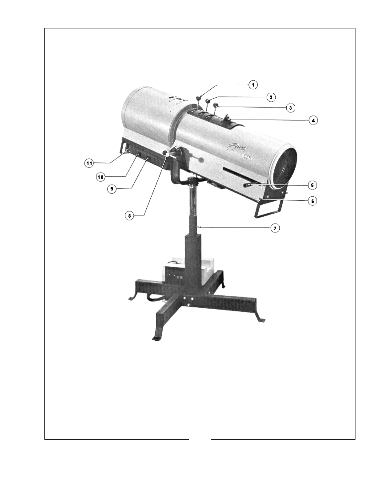
THE STRONG “575” FOLLOW SPOTLIGHT Model 41000 is an AC follow spot
complete with lamphouse, igniter, power supply, optical system, and color boomerang. It is designed
for use with the 575 watt metal halide bulb, Strong part number 41102.
THE “575” LAMPHOUSE has a deep ellipse cold-coated metal reflector designed to
operate in a fixed position, with the bulb mounted horizontally in the lamphouse. The bulb is adjustable
in relation to the reflector to permit positioning on the reflector optical center line. The igniter is
contained in the base of the lamphousing.
THE SEPARATE POWER SUPPLY comes equipped with a three-wire AC line cord
terminating in a 125 volt (±10 volt), 60 Hz. plug that can be connected to an AC outlet, and draws
approximately 7 amperes from the line. The power supply also has two switches and a toggle type
circuit breaker. The circuit breaker must be in the “ON” or “RESET” position to energize the power
supply. The two switches are an “ON” switch and “OFF” switch. The lamp may be turned on or off by
use of the appropriate switch at the power supply or at the lamphouse.
THE IGNITER in the lamphouse requires a 237 V.AC open circuit pulse, provided by a
step-uptransformerinthepowersupply,toignitethebulb. Afterignition,thepowersupplyautomatically
drops the voltage to the value required to maintain the arc.
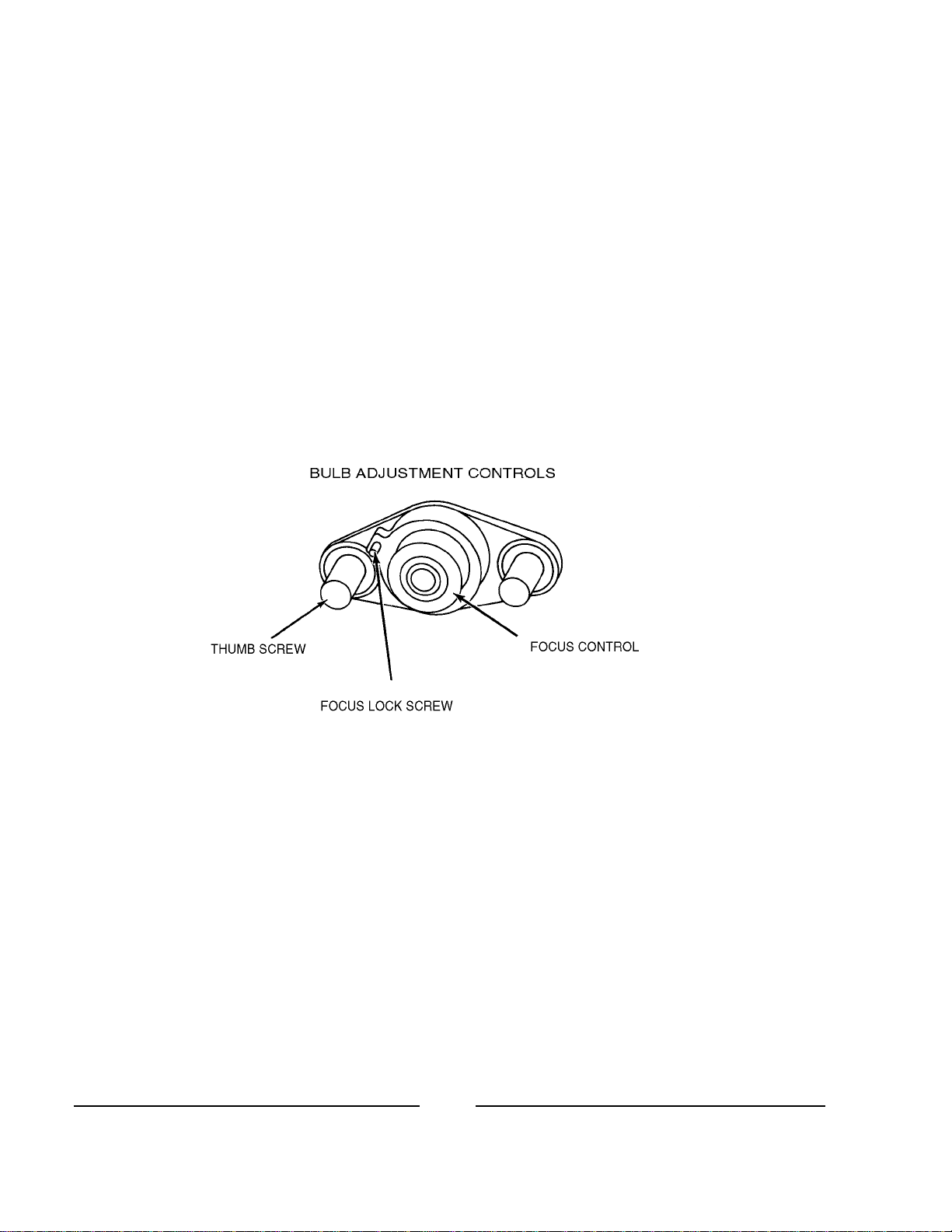
THE ADJUSTMENT CONTROL for positioning the metal halide bulb is located behind
the cover panel at the rear of the lamphouse. This control mechanism permits focus adjustment of the
bulb in relation to the reflector and also allows the bulb to be centered both vertically and horizontally on
the optical center of the reflector.
THE LAMPHOUSE has a running time meter to indicate the number of hours the bulb
has been used. It also has two switches for the “ON” and “OFF” control at the lamphouse. The lamp
can be controlled from either the power supply or the lamphouse. To break the AC supply at the power
supply and lamphouse, open the circuit breaker on the rear of the power supply.
THE POWER SUPPLY is attached to the lamphouse by a cable assembly approximately
13 feet long, terminating in an MS connector for easy attachment to the lamphouse. This cable assembly
contains all the control wires for the operation of the lamphouse and power supply.
TWO BLOWERS are used in the follow spot system and operate from the 115 volt AC
supply only while the bulb is ignited. One blower is used to cool the lamphouse and bulb; the other, in
the lens mechanism, cools the color gels and lens system.
575/001

A HOUSING INTERLOCK SAFETY SWITCH inside the lamphouse on the rear of the
lamp base pan opens the AC circuit in the lamphouse and prevents ignition of the bulb if the housing is
not in the closed position.
COLOR TEMPERATURE REDUCTION filters, required for use with television and
videotape, are available from theatrical supply dealers.
575/002
PREFACE(continued)

1. Fadeout Mechanism Control Lever 7. Height Location Pin
2. Masking Shutter Lever 8. Vertical Tilt Locking Lever
3. Iris Control Lever 9. Lamp “OFF” Switch
4. Color Boomerang 10. Lamp “ON” Switch
5. Spot Size Control Handle 11. Elapsed Time Meter
6. Spot Focus Control Knob Leveling Feet not shown
575/003

SETTING UP SPOTLIGHT
THE “575” FOLLOW SPOT is shipped in sections which must be assembled.
ASSEMBLE the four base legs to the square section of the center tube, using the 3/8-16
by 2-3/4 inch hex head cap screws and 3/8 inch split ring lockwashers to secure each leg. Insert a
leveling foot and locknut in each of the four legs.
THE INNER TUBE and support yoke has four holes on four-inch centers and will allow
an optical center height of approximately 46-1/2 inches, 50-1/2 inches, 54-1/2 inches and 58-1/2 inches
above floor level to the optical center of the lamphouse and lens system. The leveling feet may be
adjusted through a two inch range. Insert the height location pin through the hole in the outer tube and
one of the holes in the inner tube so the retaining ball on the pin extends beyond the outer tube.
THE VERTICAL TILT locking lever is on the right hand (operating) side of the yoke
assembly. Tighten this locking device securely before attempting to place the lamphouse and lens
mechanism on the support yoke.
PLACE THE LAMPHOUSE and lens mechanism on the yoke assembly, with the lens
control knob to the right hand (operator’s side); the same as the locking lever on the yoke. Line up the
four mounting holes in the bottom of the lamphouse and optical system support pan with four slotted
holes in the support saddle and secure with the four 5/16-18 wing screws. Release the vertical tilt
locking lever, move the lamphouse and optical system forward or back in the slots until the system is
balanced. Then tighten the four wing screws to hold the system in balance.
CONNECT THE CABLE ASSEMBLY from the power supply to the mating receptacle
on the bottom of the lamphouse and tighten firmly. The connector and receptacle are keyed to prevent
misalignment of the pins. Do not connect the power supply to the AC supply at this time.
THE FOUR ANGLE BRACKETS on the base legs are designed as hold-down brackets
for the spotlight. These brackets should be bolted to the floor or platform for safety purposes. The
casters are provided only for ease of movement to the operating location and must be removed from the
base legs to ensure stability during use of the follow spot.
WHEN TRANSPORTING or hoisting the follow spot, DO NOT ATTEMPT TO LIFT
the complete system, including the stand, by raising the lamphouse and lens mechanism. The most
simple procedure is to release the tilt locking lever, and the hex head screw and nut on the opposite side,
just enough to permit lifting the lamphouse and support saddle from the yoke on the stand. Then
transport as two separate assemblies.
575/004

BULB INSTALLATION AND OPERATION
REMOVE THE REAR COVER PLATE by pulling on the center section of the three
retaining pins to release the plate. This will provide an opening to grasp when removing the lamp
housing. Tighten securely the vertical tilt locking lever on the yoke. Remove the six screws attaching
the housing to the base and loosen the one at top and front of the house. Slide the housing back and off
the base for easy access to the bulb support.
ASSEMBLE THE BULB before installing it in the lamphouse. Keep fingers off quartz
envelope. Remove the two knurled nuts from both ends of the bulb. Screw the front bulb extension
(Part No. 41116) on the end of the bulb which has the evacuation or seal tip. This will place the seal
away from the reflector and towards the front of the lamphouse. The best light is obtained with the
envelope seal tip to the front of the lamphouse. Place the terminal on the end of the front bulb lead (with
the banana plug) against the end of the bulb extension #41116. Use one of the knurled nuts to secure the
lead to the extension. Make sure the connections are tight, being careful not to put any strain or finger
prints on the bulb envelope. The other knurled nut is not required; keep it for future use if needed.
PLACE THE END of the bulb without the lead through the center hole in the reflector,
into the rear support collet. Loosen the small allen head screw in the collet so the metal end cap of the
bulbcan be fully inserted intothecollet. Tighten thesetscrewfirmly against the bulb’s endcaptoensure
a good electrical contact.
THE OTHER END of the bulb (with the extension and lead) must be positioned so it will
seat at the bottom and center of the “Y” in the front support yoke. Insert the banana plug into the
receptacle on the air duct.
SLIDE THE HOUSING back onto the base; note the sides of the housing should be
inserted into the slots on the base. Do not replace the rear cover plate until the bulb alignment procedure
(following) has been completed. Slide the cover under the top screw and replace the six screws along
the bottom of the housing.
PLUG THE AC LEAD CORD from the power supply into any grounded three-wire, 15
ampere, 120 volt outlet. Set the circuit breaker on the rear of the power supply case to the “ON” or
“RESET” position. Press the green “ON” switch at either the power supply or at the lamphouse and the
bulbwill ignite.
ALLOW THE BULB to heat up for two or three minutes to reach full brightness, then
proceed with the following instructions for alignment of the bulb with the reflector.
575/005

THE CENTER SECTION of the control is a threaded member that focuses the bulb in
relation to the reflector. Turning this adjustment moves the bulb along the optical centerline of the
reflector. Turning this section clockwise moves the bulb away from the reflector. The small knurled
screw to the left of this section can be tightened to lock the focusing mechanism, after the following
procedures have been completed.
THE THUMB SCREWS on either side of the focusing control lock the horizontal and
vertical adjustment mechanism in position.
TO FOCUS THE METAL HALIDE BULB and obtain the best light on the stage the
method outlined below is the most suitable.
MOVETHESPOTSIZECONTROLhandleonthelargelenscarriage all the way forward
to project the smallest spot possible, with the iris, the masking shutter and the dimming control or
douser in the full open position. Project the spot to a wall or similar flat perpendicular area opposite the
follow spot.
TURN THE CENTER FOCUSING SECTION of the bulb position control clockwise
until a brown color with a hot spot is projected on the wall.
LOOSEN THE TWO THUMB SCREWS, one on either side of the center focusing
section, just enough to permit manual movement of the complete assembly. The bulb adjustment control
will now move around these two spring-loaded thumb screws.
575/006
BULB INSTALLATION AND OPERATION(continued)

MOVE THIS CONTROL SECTION around the two screws until the hot spot is centered
in the brown circle of the reflector. After the hot spot is centered, tighten the two thumb screws to lock
this adjustment section and turn the center focus control section counterclockwise to obtain the brightest
light with the best light distrubution. Rotate the lens spot focus control knob, located on the front of the
lens mechanism, to obtain the sharpest edge possible on the projected spot.
REPLACE THE REAR COVER PLATE over the bulb adjustment control mechanism.
Secure using the push-type fasteners.
THEFOLLOWSPOT may be turned offat the lamphouse or the power supply, whichever
is most convenient to the operator. It is recommended that the circuit breaker on the rear of the power
supply be placed in the “OFF” position, to function as a line switch, when the spot is off for any extended
period of time.
WHEN TRANSPORTING, or if the bulb may be subjected to a hard shock when moving
to another location, remove the assembled metal halide bulb from the lamphouse by reversing the
installation procedures. If the control section of the bulb adjustment is not changed, the bulb should be
able to be replaced without any necessity to repeat the aligning procedures.
THE METAL HALIDE BULB ignites better when cold. After extinguishing the bulb,
allow at least one minute cooling before attempting re-ignition.
EXPECTED BULB LIFE is 750 hours, but because of manufacturing tolerances, some
bulbs may lose color quality before this period.
BULB LIFE can be maximized by avoiding repeated ignitions. Allow the lamp to burn
throughout the spotlight’s use cycle, dousing out with the masking shutter blades or fadeout mechanism
as required.
RECORD the elapsed time meter reading when replacing a bulb.
575/007
BULB INSTALLATION AND OPERATION (continued)

OPERATION OF OPTICAL SYSTEM
THE IRIS CONTROL is the front lever which projects through the top of the optical
system housing. When this lever is to the left, looking at the spotlamp from the rear, the largest aperture
is provided. Smaller apertures are obtained as the lever is moved to the right.
THE SPOT SIZE CONTROL HANDLE is located on the right side of the optical system
just above the base pan. A variation of spot sizes from full flood to a small spot can be obtained by
moving the spot size control from one extreme to the other. Beam intensity is increased by this optical
system when reducing from flood to spot and maximum intensity is reached when the spot size control
is in the extreme forward position.
THE MAXIMUM FLOOD SPOT is obtained with the iris control lever to the left (away
from operating side) for the large aperture and with the spot size control handle moved as far as possible
toward the rear.
SMALLERSIZED SPOTS are porjected as the spot size control handleismovedforward.
Most of the spot sizes needed wiill be produced with the iris in its maximum open position.
FOR A “HEAD SPOT,” or any spot size smaller than can be obtained with the spot size
control handle in its extreme forward position, shift the iris control lever to the right (toward operating
side) for a smaller aperture. The iris control lever should always be returned to its extreme left position
before the spot size control handle is again moved to obtain larger spots.
THE MASKING SHUTTER LEVER is the middle lever projecting through the top of
the optical system housing. The masking shutter blades are operated by this lever to shape the projected
spot to a rectangle, strip spot, or dousing.
THE DISENGAGED POSITION of the masking shutter lever is to the extreme right
(toward operating side) and varying degrees of masking to complete cutoff are obtained by moving the
lever to the left (away from operating side).
CAUTION
ULTRAVIOLET RADIATION is emitted when the bulb is ignited. Wear
protective clothing and goggles or glasses when adjusting the shutter
bladesorperforminganyservicewith theopticalsystem housingremoved.
575/008

THEANGLE OF THE MASKING SHUTTER BLADES can be adjusted tocompensate
for the horizontal projection angle. Remove large lens shaft handle and knobs. Remove the optical
system housing, and loosen (with an angle screwdriver) the screws holding each of the masking shutter
blades just enough to allow adjustment. Ignite the bulb and adjust the angle of the bottom blade by
tapping with a screwdriver so its projected edge lies parallel to the footlights; tighten the mounting
screw in the bottom blade.
OPERATE THE MASKING SHUTTER LEVER to close the blades. Adjust the upper
blade to close in line with the bottom blade. Tighten the screw to secure the upper blade.
THEFADEOUT MECHANISM AND DOUSER CONTROL is the rear lever projecting
through the top of the optical system housing. This lever controls the intensity of light from complete
fadeout when the lever is to the left, to full intensity when the lever is to the right.
THE LENS FOCUSING KNOB is located on the operating side of the optical system
base pan (forward end) and is used to adjust the optical system for the length of throw. When making an
adjustment rotate the spot focusing knob until the sharpest edge is obtained on the projected spot.
Moving the large lens to its center of travel and then adjusting for a sharp edge should give satisfactory
results for the full movement of the lens system.
575/009
OPERATION OF OPTICAL SYSTEM (continued)

HANDLING THE SPOTLIGHT
GENERALLY THE BEST POSITION for the operator to stand is near the center of the
spotlight, on the right hand side, although the angle of tilt and the size of porthole may alter the position
for the most convenient operation.
EACH OPERATOR will, after a few minutes of operation, generally develop his own
system and preferred position for operating the follow spot.
THE VERTICAL TILT LOCK LEVER located on the base assembly can be set to give
the required amount of friction on the spotlight to suit the individual operator.
THE LENS CARRIAGE FRICTION BRAKE is located on the outrider of the large lens
carriage and is preset at the factory for the most satisfactory operation. Individual requirements vary
and the brake can be adjusted to suit the operator. Remove the color boomerang, reach through the
color gel opening and loosen the locknut. Then adjust the screw on the friction brake until the desired
tension is applied to the large lens carriage. Tighten the locknut and replace the color boomerang.
OPERATION OF COLOR BOOMERANG
THE COLOR BOOMERANG is equipped with six color filter discs containing the
following colors in order from rear to front:: (1) Amber, (2) Flesh Pink, (3) Daylight Blue, (4) Light Sky
Blue, (5) Primary Blue, (6) Light Red. Keep the darkest or most dense colors to the front of the
boomerang. A heat filter is mounted in a fixed position behind the boomerang to protect the gels.
THE SIX COLOR DISC LEVERS are mounted in the cover plate casting directly in
front of the aperture selector lever. To insert a color disc in the light beam, move the proper color disc
lever to the left as far as possible. To release a color disc, move the lever to the extreme right. Be sure
that the lever is always fully returned to the limit of its movement.
TO REMOVE A COLOR DISC ASSEMBLY, remove the knobs from the aperture
selector, masking shutter and fadeout levers. Remove the two end screws from the cover plate casting
and lift off the complete boomerang assembly. The two split rivets holding the color disc assembly can
now be removed and a new color disc assembly installed. Only the six above-mentioned color discs are
supplied with the boomerang; additional colors are available from theatrical supply dealers.
575/010

MAINTENANCE
TO CLEAN THE SMALL LENS, remove the color boomerang assembly and using a
good grade of alcohol and piece of lens tissue (facial tissue can be used as a substitute), gently wipe both
sides of the lens until the surface is clean.
THE BACK SURFACE OF THE LARGE LENS can readily be cleaned by using the
same access hole as above with the large lens carriage in the rear position.
TO CLEAN THE FRONT SURFACE of the large lens, slide the lens carriage to the full
forward position. The front surface is now readily accessible through the front of the housing.
THE REFLECTOR should be cleaned periodically with a clean, soft lint-free cloth to
remove any dust from the reflecting surface.
THE NEGATIVE LENS, mounted on the support for the fade-out mechanism, must be
removed for cleaning. Use the same materials for cleaning this lens as recommended for both the small
and large lens. The negative lens must be replaced with the curved surface facing towards the reflector
and metal halide bulb.
THE INSIDE of the lamphouse and lens mechanism and the blowers should be cleaned
periodically, depending on the dust conditions at each installation. The blower blades need cleaning to
remove the dust build-up that accumulates over a period of time.
THE FOLLOW SPOT does not require any lubrication.
575/011

575/012
LAMPHOUSE SCHEMATIC DIAGRAM

575/013
PARTS LIST, SCHEMATIC DIAGRAM
Ref.
Desig. Part No. Description
- 41976 Igniter & Leads Assembly
- 41104 Igniter (220 V.AC, 50/60 Hz.)
- 41975 Igniter High Voltage Wire (2)
B1 61-98002 Blower, Lamphouse (115 V.AC, 50/60 Hz.)
- 81272 Blower, Lamphouse (230 V.AC, 50/60 Hz.)
- 41970 Blower Lead, Lamphouse
B2 61-98002 Blower, Lens Mechanism (115 V.AC, 50/60 Hz.)
- 81272 Blower, Lens Mechanism (230 V.AC, 50/60 Hz.)
- 41971 Blower Lead, Lens Mechanism
DS1 41193 Lamp & Switch (“ON” S1; 115 V.AC)
- 41193 Lamp & Switch (“ON” S1; 230 V.AC)
DS2 41189 Lamp & Switch (“OFF” S2; 115 V.AC)
- 41194 Lamp & Switch (“OFF” S2; 230 V.AC)
DS3 41102 HMI Bulb (575 Watt, Double-Ended)
- 41956 Lead Wire (TB1 to Duct) Assembly
- 41974 High Voltage Lead & Banana Plug (1)
J1 41983 Power Supply Cable Assembly
P1 41969 MS Receptacle, Wired Assembly
- 41110 MS Receptacle
S1 41967 “ON” Switch & Leads Assembly (DS1; 115 V.AC)
- 41188 “ON” Switch (115 V.AC)
- 41953 “ON” Switch & Leads Assembly (DS1; 230 V.AC)
- 41193 “ON” Switch (230 V.AC)
S2 41968 “OFF” Switch & Leads Assembly (DS2; 115 V.AC)
- 41189 “OFF” Switch (115 V.AC)
- 41954 “OFF” Switch & Leads Assembly (DS2; 230 V.AC)
- 41194 “OFF” Switch (230 V.AC)
S3 41973 Interlock Switch & Leads (115/230 V.AC)
- 80168 Interlock Switch, Housing (S3; 115/230 V.AC)
T1 41966 Elapsed Time Meter (115 V.AC, 60 Hz.)
- 41964 Elapsed Time Meter (230 V.AC, 50 Hz.)

575/014
Lamphouse & Lens Mechanism
FIGURE 1

575/015
Item Part No. Description
1 00254 Screw, 8-32 x ¼" Fillister Head
- 00891A Lockwasher, #8 Shakeproof (Bronze)
2 41152 Retaining Ring, LargeLens
3 41101 Lens, 9-1/2" Diameter, 20” F.L.
4 51509 Handle, Large Lens
- 41185 Shaft, Large Lens Handle
5 00381 Screw, 10-24 x 3/8" Fillister Head
- 00894 Lockwasher, #10 Split Ring
6 41134 Rod, Lens Carriage Slide
7 41958 Ribbon Assembly, Focus Adjusting
- 00179 Screw, 6-32 x ¼" Fillister Head
- 00884 Lockwasher, #6 Split
- 00919 Cotter Pin, 1/16" x ½"
8 45224 Stud, Lens Focus Adjusting
- 00687 Screw, ¼-20 x ½" Hex Head
- 00876 Lockwasher, ¼" Split Ring
9 51168 Knob, Focus Adjusting
- 51202 Set Screw, Focus Adjusting Knob
- 41136 Threaded Rod, Focus Adjusting
- 00835 Washer, ¼" Flat
10 41135 Block, Lens Focus
11 00687 Screw, ¼-20 x ½" Hex Head
- 00876 Lockwasher, ¼" Split Ring
12 41173 Handle, Base Pan
13 51158 Pulley, Small
- 51160 Stud, Pulley
14 41994 Pan Assembly, Base
15 49361 Bracket, Handle (Used in early models only)
- 01525 Thumbscrew, 5/16-18 x ¾"
- 01502 Lockwasher, 5/16" Shakeproof
- 00853 Washer 5/16" Flat
- 49362 Grip, Vinyl Handle
16 61-98002 Blower, Lens Housing (125 V.AC, 50/60 Hz.)
- 81272 Blower, Lens Housing (230 V.AC, 50/60 Hz.)
- 93131 Guard, Blower
PARTS LIST
Figure 1

575/016
Item Part No. Description
- 48316 Bushing, Nylon Snap
- 00192 Screw, 6-32 x 2" Fillister Head
- 00892 Lockwasher, #6 Shakeproof
- 41971 Cord & Plug, Lens Blower
17 51162 Spring, Tension (Lens Carriage)
18 51120 Clip, Spring & Ribbon
- 01742 Screw, 8-32 x ¼" Pan Head
- 00891A Lockwasher, #8 Shakeproof
19 91219 “E” Ring, External (Flat)
20 51114 Collar, Stop
- 00720 Set Screw, 10-32 x 1/16" Cup Point, Allen Socket
21 01345 Screw, 10-32 x ½" Pan Head
- 01344 Lockwasher, #10 Shakeproof
22 41995 Welded Assembly, Instrument Case
- 00541 Screw, ¼-20 x ½" Pan Head
23 41139 Insulator, Air Duct
24 61-98002 Blower, Lamphouse (115 V.AC, 50/60 Hz.)
- 81272 Blower, Lamphouse (230 V.AC, 50/60 Hz.)
- 83131 Guard, Blower
- 41970 Cord & Plug, Lamphouse Blower
- 01763 Screw, 6-32 x 1" Pan Head
- 61127 Clip, Blower Mounting
25 41969 MS Receptacle & Wires
- 41110 Receptacle, MS (less wires)
- 01726 Screw, 4-40 x 5/16" Fillister Head
- 01620 Nut, 4-40 Hex
- 01621 Lockwasher, #4 Shakeproof
26 41968 “OFF” Switch & Wires (115 V.AC)
- 41189 “OFF” Switch (115 V.AC)
- 41954 “OFF” Switch & Wires (230 V.AC)
- 41194 “OFF” Switch (230 V.AC)
27 81283 Block, Terminal
- 41142 Insulation Strip, Terminal Block
- 00259 Screw, 8-32 x 5/8" Fillister Head
- 00795 Nut, 8-32 Hex
- 00886 Lockwasher, #8 Split Ring
PARTS LIST, Figure 1 (continued)

575/017
Item Part No. Description
28 41967 “ON” Switch & Wired (115 V.AC)
- 41188 “ON” Switch (115 V.AC)
- 41193 “ON” Switch (230 V.AC)
29 41976 Igniter & Wires
- 41104 Igniter, High Voltage; 30 kV.
- 41146 Insulator, Igniter
30 41966 Meter, Elapsed Time (115 V.AC, 60 Hz.)
- 41964 Meter, Elapsed Time (230 V.AC, 50 Hz.)
- 41109 Plastic Cover, Hour meter
- 01306 Screw, 6-32 x 5/16" Pan Head
- 00892 Lockwasher, #6 Shakeproof
31 46137 “E” Ring, External Bowed
32 91219 “E” Ring, External (Flat)
33 51114 Collar, Stop
- 00720 Set Screw, 10-32 x 3/16" Cup Point, Allen Socket
34 80168 Switch, Interlock 115/230 V.
- 72178 Bracket, Interlock Switch
- 00182 Screw, 6-32 x 7/16" Fillister Head
- 00793 Nut, 6-32 Hex
- 00892 Lockwasher, #6 Shakeproof
35 41975 Wire Assembly, Igniter H.V.
36 90416A Ring, Truarc
37 25118 Bulb Support Assembly
- 00712 Set Screw, 8-32 x ¼" Cup Point (Bulb Retaining)
38 65132 Thumb Screw, Bulb Adjustment Locking
39 65959 Focus Screw & Bearing Assy.
40 65150 Washer, Flat
41 65116 Bulb Adjust Casting
- 65153 Screw, Thumb
- 65154 Ball, Nylon Locking
42 01742 Screw, 8-32 x ¼" Pan Head
- 00891A Lockwasher, #8 Shakeproof
43 41992 Reflector Support
- 48324 Bushing, Wire
44 00541 Screw, ¼-20 x ½" Pan Head
- 00889 Lockwasher, ¼" Shakeproof
PARTS LIST, Figure 1 (continued)

575/018
Item Part No. Description
45 41140 Rod, Reflector Mounting
46 41963 Lamphouse Cover, Welded Assembly
- 41124 Danger Sign, Lamphouse
- 01639A Rivet, 1/8" Domed Head
- 01304 Screw, 8-32 x 5/16" Pan Head
- 41961 Rear Access Plate Assembly
- 41179 Cover, Lamphouse Access
- 45270 Plunger, Cover Plate
- 45271 Grommet, Cover Plate
47 00541 Screw, ¼-20 x ½" Pan Head
- 00889 Lockwasher, ¼" Shakeproof
48 44154 Clip, Lens Retaining
- 00255 Screw, 8-32 x 5/16" Fillister Head
- 00891A Lockwasher, #8 Shakeproof
49 41119 Lens, Negative
50 41102 Lamp, HMI 575 Watt
- 41116 Extension., HMI Bulb 575 W.
51 41980 Bulb Support
52 23756 Reflector, Flanged
53 41114 Housing Support Casting
- 00687 Screw, ¼-20 x ½" Hex Head
- 00876 ¼" Split Lockwasher
- 41945 Light Shield (not shown)
- 01304 Screw, 8-32 x 5/16" Pan Head
54 41975 Wire Assy, High Voltage Bulb Lead
55 01791 Screw, 8-32 x 1" Round Head, Nylon
- 65171 Lava Bushing
- 48126A Washer, Insulating
56 41155 Air Duct Casting
- 72181 Receptacle, Banana Plug
- 01423 Screw, 10-32 x 5/16” Pan Hd.
- 00885 Lockwasher, #10 Shakeproof
- 01721 Set Screw, 8-32 x 5/16” Hex Socket
57 - Fadeout, Chopper & Iris (See Figure 2)
58 00253 Screw, 8-32 x 3/16" Fillister Head
- 00891A Lockwasher, #8 Shakeproof
PARTS LIST, Figure 1 (continued)
This manual suits for next models
1
Table of contents
Other Strong Spotlight manuals
Popular Spotlight manuals by other brands

Philips
Philips SmartSpot 57958/48/16 Specifications

Philips
Philips SmartSpot 57966/48/16 user manual

Meister
Meister WU7490590 operating instructions

Larson Electronics
Larson Electronics Golight Stryker GL-30064ST instruction manual

Tri-Tronics
Tri-Tronics NIGHTRAZOR owner's manual

Vector
Vector Sportspot 90519935 instruction manual