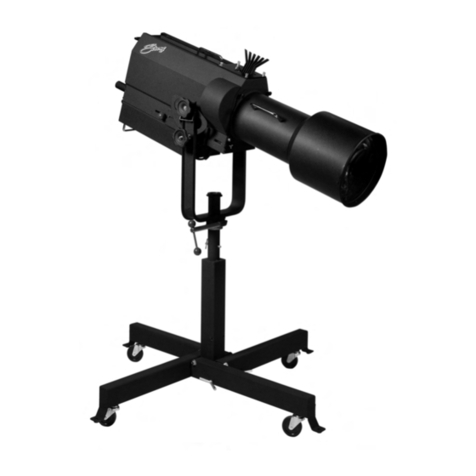
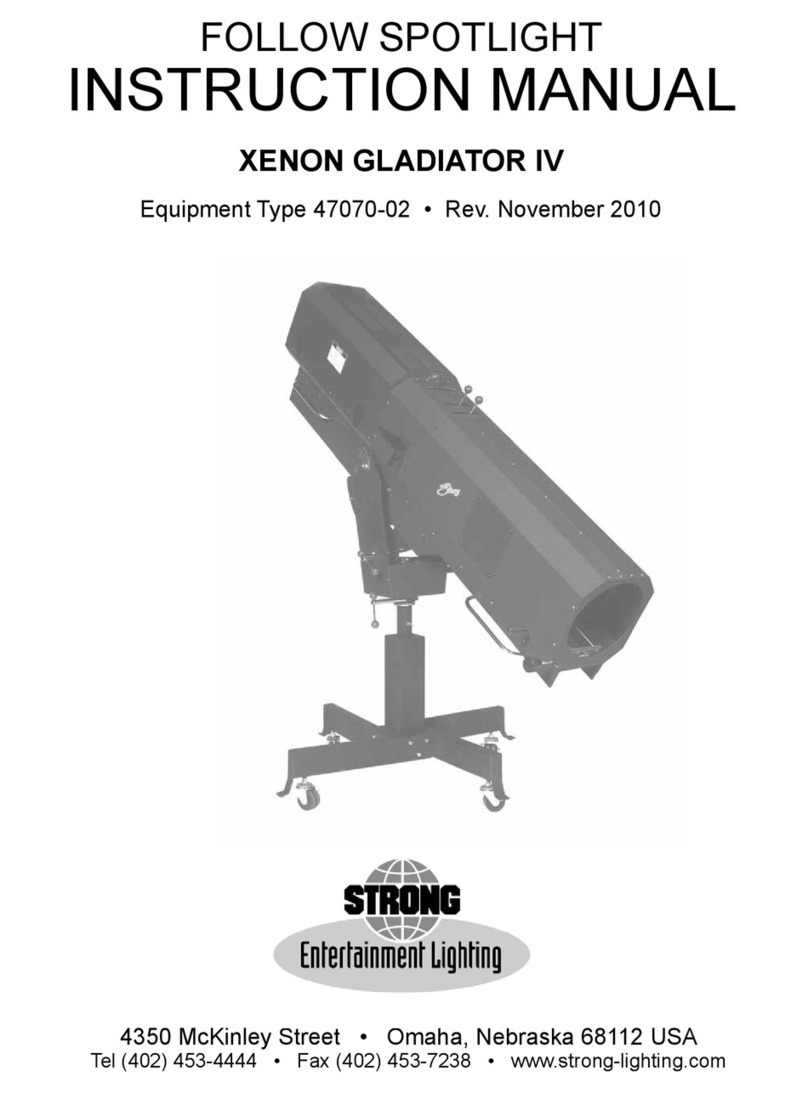
Strong TROUPERETTE IV User manual

TROUPERETTE IV
Follow Spotlight
Type 45004-1,2
Rev. March 2002
STRONG INTERNATIONAL
a division of Ballantyne of Omaha, Inc.
4350 McKinley Street
Omaha, Nebraska 68112 USA
Tel 402/453-4444 • Fax 402/453-7238

FIGURE 1
Saddle Clamp
Screw
Friction Washer
VerticalTilt
Locking Knob
Spot Size
Control Handle
Focus Adjusting
Knob
LampYoke
InnerTube
Clamping Lug
Clamping Stud
Lamp & Optical
System Housing
Name &
Data Plate
Lamp Saddle
Power Switch
AC Power Cord
Clamping Collar,
Height Adjustment
Outer Tube
Stand Leg
Caster
TROUPERETTE IV

TROUPERETTE IV
Spotlight Set-Up
FASTEN THE THREE STAND LEGS (Figure 1) to the lower end of the outer tube
using the (6) cap screws, lockwashers, and hexnuts furnished in the accessory box. Insert the casters
into the holes provided in each leg only if the spotlight is to be portable. If the spotlight is to remain in
a fixed location, do not insert the casters, but use the holes in the stand legs for hardware (not supplied)
to bolt the stand to the floor.
TIGHTEN THE CLAMPING STUD to secure the height adjust collar. Mount the spot-
light head to the lamp yoke by lowering the lamp saddle into the slots provided. Make certain the
leather friction washer disc is between the flat metal friction surfaces of the saddle and yoke. Clamp
the spotlight head in a horizontal position by tightening the cast vertical tilt locking knob onto the
saddle clamp screw.
TO SET THE DESIRED THE HEIGHT OF THE SPOTLIGHT, loosen the clamping
stud of the height adjustment clamp and raise or lower as desired. The height range from floor to
optical center is 43 inches (1.1 m) to 60 (1.5 m) inches.
THE TROUPERETTE IV requires a 1000 watt, 120 volt Type FEL projection bulb for
domestic (USA) operation. An export model (45004-02) is available, and uses a 1000 watt, 240 volt
Type FEP bulb. The rated life of either bulb is 250 hours, and it is advisable to have a spare bulb
available (FEL - Part No. 45246; FEP - Part No. 45272).
TO INSTALL THE BULB, dismount the rear Name & Data Plate by removing the (3)
socket head cap screws. See the Detail drawing on Figure 4. Loosen the two thumb screws (Item 11)
enough to slide the support bracket and bulb socket (Items 13 & 14) through the rear opening and out of
the lamphouse. Do not alter the position of the stop plate (Item 5). Grasp the bulb by its metal base and
push it firmly into the center of the socket (Item 14). CAUTION: Avoid touching the bulb envelope;
skin oils in fingerprints will etch the envelope and possibly shorten the expected bulb life. Remove any
accidental fingermarks immediately using alcohol and a clean, soft cloth.
SLIDE THE ASSEMBLED BRACKET and bulb back onto the support (Figure 4, Item
12) up to and resting against the stop plate (Item 5). Tighten the two thumb screws (Item 11) to secure
the bulb and bracket in position, and replace the rear cover plate.
CONNECT THE LEAD CORD PLUG to an AC receptacle of the correct voltage (see
Equipment Data Plate; 45004-01 = 120 V.AC, 45004-02 = 240 V.AC). Turn the lamp ON by means of
the power switch and inspect the projected spot. If the spot is not satisfactory, see the instructions
following regarding Reflector & Bulb Adjustments.
WHEN MOVING THE SPOTLIGHT from one location to another, it is highly advis-
able to remove the bulb and pack it separately. The bulb filament is very fragile and susceptible to
breakage from jars and shocks, particularly after prolonged operation.
TR4/001

OPERATION OF OPTICAL SYSTEM
THE SPOT SIZE CONTROL HANDLE (“trombone”) is located on the right-hand side
of the spotlight housing just above the base pan. A variation of spot sizes in a ratio of 5:1 can be
obtained with the movement of the Spot Size Control from one extreme to the other.
THE APERTURE SELECTOR (“iris”) is the front handle projecting through the top of
the lamphouse cover plate casting. When this handle is to the left (viewing spotlight from the rear), the
largest aperture is open. Smaller apertures are obtained as the handle is moved to the right.
THE SPOT FOCUSING CONTROL KNOB is located on the lower right side of the
optical system base pan, toward the front of the unit. This control is used to adjust the optical system
for the length of throw. A nominal (“average”) setting of this control can be made by positioning the
aperture selector (iris) handle to the right, and sliding the spot size control (trombone) to the extreme
front. Then rotate the knob until the sharpest white light is obtained on the projected spot. If the
spotlight remains at a given throw point, the focus control can be set to best sharpen the edge of the
projected spot.
MAXIMUM “FLOOD” SPOT is obtained by opening the aperture selector (iris) by
moving its control handle to the left, and sliding the spot size control (trombone) to its extreme rear
stop. If projecting a flood spot for a prolonged period, it may be desirable to adjust the focus control to
sharpen the edge of the spot.
SMALLER SIZED SPOTS are projected as the spot size control (trombone) is moved
forward. Most commonly used spot sizes (head-to-foot “body” spots) are produced with a large aper-
ture (iris open) and a small spot (trombone forward).
FOR A “HEAD” SPOT, or any spot smaller than can be obtained with the spot size
control (trombone) in the extreme forward position, shift the aperture selector handle toward the right
to close the iris and project a smaller spot. The aperture selector handle should always be returned to its
extreme left setting before the spot size control handle is again moved to project larger spots.
A “DIFFUSED” SPOT is projected by pulling the spot size control (trombone) back
toward “flood” setting while closing the iris (aperture selector handle toward right). A “diffused” spot
is seldom required, and is a “soft” edged spot with low light intensity.
THE MASKING SHUTTER AND DOUSER HANDLE (“chopper”) is the rear lever
projecting through the top of the lamphouse cover casting. The masking shutter (chopper) blades are
operated by this lever to shape the projected spot to a rectangle, a light strip, or to douse the spot for
blackout. When the masking shutter control lever is to the extreme right, the chopper blades are open,
and a round spot is projected. Varying degrees of top-and-bottom masking, to complete douse (light
cutoff), are obtained as the lever is moved to the left.
TR4/002

ANGULAR ADJUSTMENT OF MASKING SHUTTER BLADES
THE ANGULARITY of the masking shutter (chopper) blades can be adjusted to com-
pensate for the horizontal projection angle, for example, if the spotlight is positioned to the left or right
of center stage. Remove the spotlight housing to expose the optical system.
AN UNBALANCED CONDITION will occur when the housing is removed, so the
vertical tilt locking knob should be tightened. Slide the large lens forward by moving the trombone
handle to the extreme forward position; remove the spot size control handle. Unscrew the knobs from
the iris and chopper levers. Remove all screws securing the housing to the base pan, and lift the
housing from the base pan.
SEE THE DETAIL DRAWING on Figure 5. Loosen, but do nor remove, the screws
(Item 16) securing each of the chopper blades (Items 14 & 18). Angle the lower blade so that it lies
parallel with the footlights, and tighten the lower screw. Operate the masking shutter lever to close the
chopper blades, and cause the upper blade to align to the lower blade. Secure the upper blade by
tightening its mounting screw. Check the setting by lighting the bulb and projecting a narrow strip spot
to the stage. Replace the housing and controls.
OPERATION OF THE COLOR BOOMERANG
THE COLOR BOOMERANG (Figure 6) is equipped with six 3-1/2" color filter discs
containing the following colors, in sequence, from rear to front: (1) Amber, (2) Flesh Pink, (3) Medium
Pink, (4) Light Magenta, (5) Special Lavender, and (6) Special Steel Blue. Additional colors are avail-
able from theatrical supply dealers; specify ROSCOLUX®(or equivalent) high temperature gels.
THE SIX COLOR DISC CONTROL LEVERS are mounted in the cover plate directly
in front of the aperture selector (iris) lever. To insert a color disc into the light beam, move the desired
disc lever to its extreme left position. To release a color, return the lever to the extreme right. Always
operate the color levers to the limits of their travel.
TO DISMOUNT A COLOR DISC, unscrew the knobs on the iris and chopper levers
and remove the two screws securing the top cover casting to the housing. Lifting the top cover plate
from the spotlight will remove the boomerang assembly. Each color disc is mounted to its control arm
by two screws. See Figure 6 Parts List for replacement discs.
TR4/003

HANDLING THE SPOTLIGHT
GENERALLY THE BEST POSITION FOR OPERATION is to stand near the center of
the spotlight on the right-hand side. The angle of tilt and the size and location of the porthole may,
however, alter the position for most convenient operation. One hand should be kept on the spot size
control handle, as the spot can thus be directed and changed in size simultaneously. The other hand is
used for operation of the optical system and boomerang control levers, and generally steadying the
spotlight.
THE VERTICAL TILT LOCKING KNOB on the side of the lamp saddle can be tight-
ened or loosened to provide the desired degree of friction to suit the individual operator. A brake screw
on the outrider of the large lens carriage (Figure 3, Item 15) can also be set to provide more or less
“drag” to the spot size control handle.
REPLACEMENT AND ADJUSTMENT OF REFLECTOR AND BULB
THE REFLECTOR has been carefully aligned at the factory for maximum light collec-
tion and transmission, and under normal circumstances, its position should not be changed. If it
becomes necessary to replace the reflector, tighten the vertical tilt locking knob to immobilize the
spotlight, unscrew the knobs from the iris and chopper control levers, remove the spot size control
handle, and dismount the spotlight housing.
SEE THE DETAIL DRAWING on Figure 4. Dismount the reflector (Item 15) by re-
moving only the reflector mounting screws (Item 2). Do not remove plate mounting screws (Item 16) or
otherwise alter the location of the mounting plate (Item 1). Install the replacement reflector (45245)
without disturbing the position of the mounting plate.
IF THE ORIGINAL or a replacement bulb fails to produce a suitable spot, it may be (a)
the bulb is not properly seated in its socket, or (b) because of manufacturing tolerances, the position of
the bulb filament differs slightly from the bulb used prior. Project a spot with the iris open and the spot
size control handle about five inches back from the front of the lamphouse. Rotate the focus knob to
obtain the sharpest possible spot.
IF A DARK AREA APPEARS at the top or bottom of the spot, slightly loosen the two
screws (Figure 4, Item 8) and move the bracket (Item 12) up or down on its slots to obtain even illumi-
nation. When corrected, tighten the two bracket mounting screws.
TR4/004

IF THE CENTER OF THE SPOT appears darker or brighter than the edges, loosen the
two thumb screws (Figure 4, Item 11) and move the bracket (Item 13) slightly to the rear of the lamp-
house. If this does not balance the light, the stop plate (Item 5) must be moved a little toward the front
of the bracket (Item 12). Loosen the screws (Item 6) just enough to move the stop plate (Item 5) in
small increments until an even spot is projected. When a satisfactory spot is obtained, tighten all
fasteners securely.
MAINTENANCE
TROUPERETTE LENSES SHOULD BE CLEANED with a liquid lens cleaner formu-
lated for use with coated lenses, and lens tissue. These items are available from theatrical or motion
picture supply dealers. A good grade of alcohol and facial tissue may be substituted. Do not use
abrasive cleansers of any kind.
TO CLEAN THE SMALL LENS, remove the slotted top cover plate and boomerang to
access the rear lens carriage. The back surface of the large lens can also be cleaned through this
opening when the spot size control handle is moved to its extreme rear position. Returning the trom-
bone handle to its front position allows the front surface of the large lens to be cleaned through the front
opening of the spotlight housing.
THE INTAKE GRILLE of the fan should be cleaned regularly to prevent dust build-up,
which could restrict air flow. A reduction in forced-air cooling will greatly shorten the life of the FEL
or FEP bulb; replace the fan if defective. The fan motor incorporates sealed bearings and requires no
lubrication.
TR4/005

PARTS LISTS
Trouperette IV
Type 45004
FIGURE 2 Floor Stand & Yoke
FIGURE 3 Base Pan & Lens Mechanism
FIGURE 4 Bulb & Reflector Mount
FIGURE 5 Optical System
FIGURE 6 Color Boomerang
Replacement Parts for Strong Trouperette IV Follow Spotlights are available through authorized
Strong International Dealers only. Order by Part Number and Description.
Goods returned to Strong International must be marked with a Return Authorization number issued
by Strong to its Dealer prior to shipment. Return freight must be prepaid.
TR4/006

FIGURE 2
TR4/F02

PARTS SHOWN ON ILLUSTRATIONS
Figure Item Part No. Description
2 1 45152 Screw, Saddle Clamp
2 45151 Friction Washer, Leather
3 45153 Vertical Tilt Locking Knob, Cast
4 45987 Inner Tube & Yoke, Welded Assembly (incl. Item 15)
5 4370753 Thumb Screw, 3/8-16 x 3/4"
6 45160 Clamping Lug
7 45157 Outer Tube, Base Stand
8 45156 Leg, Base Stand (3 req’d.)
9 34014 Swivel Caster, Plastic (3 req’d.)
10 4317000 Split Lockwasher, 5/16"
11 4318004 Half Nut, 5/16-18 Hex
12 4311751 Cap Screw, 5/16-18 x 1-3/4" Hex Head
13 45918 AC Power Cord with Molded Plug, 120 V.AC
— 49295 Plug, 230 V.AC (Export)
14 45159 Collar, Height Adjust Clamp
15 45987 Inner Tube & Yoke, Welded Assembly (incl. Item 4)
— 45966 Trouperette Base & Stand Assembly (Items 4 - 15)
16 45280 Name & Data Plate/Back Cover
17 4100500 Mounting Screw, 10-32 x 1/2" Socket Head
— 4107101 Flatwasher, #10
— 4108021 Tinnerman Nut, #10
18 72-00216 Spotlight Housing, Welded Assembly (see Figure 3, Item 21)
Figure Item Part No. Description
3 1 4080310 Screw, 8-32 x 5/16" Pan Head
- 4087000 Lockwasher, #8 Split Ring
2 51493 Ring, Large Lens Carriage
3 51492 Rubber Edge Mounting
4 45209 “E” Ring, 3/16"
5 4107101 Flatwasher, #10
6 51133 Lens Focus Adjusting Block
7 45208 Shaft, Focus Adjusting
8 51114 Stop Collar, Slide Rod
- 4100252 Set Screw, 10-32 x 1/4" Cup Point
9 48103 Knob, Focus Adjust
10 4060250 Screw, 6-32 x 1/4" Pan Head
— 4067001 Lockwasher, #6 Shakeproof
11 45224 Stud, Lens Focus
— 4250508 Screw, 1/4-20 x 1/2" Pan Head
12 51992 Focus Ribbon, Welded Assembly
13 51509 Handle, Red Plastic
— 51508 Shaft, Spot Size Control (Trombone)
— 4378001 Hexnut, 3/8-16
TR4/007

FIGURE 3
TR4/F03

Figure Item Part No. Description
3 14 51158 Lens Ribbon Pulley, Small
(Con’d.) — 51160 Pulley Stud
15 4251001 Screw, Lens Friction Brake; 1/4-20 x 1" Hex Head (Nylon)
— 4258015 Lock Nut, Friction Brake; 1/4-20 Hex (Nylon)
16 51162 Expansion Spring, Lens Ribbon
17 45945 Base Pan & Saddle, Welded Assembly
18 51157 Lens Ribbon Pulley, Large
— 51160 Pulley Stud
— 4087100 Spacer Washer, #8 Flat
19 45930 Small Lens Carriage, Welded Assembly
20 4100500 Screw, 10-32 x 1/2" Socket Head
— 45258 Shim (below Aperture Support)
21 72-00216 Spotlight Housing, Welded Assembly (see Figure 2, Item 18)
— 4100250 Mounting Screw, 10-32 x 1/4" Binding Head
22 61-98002 Fan, 4" Square Frame, 120 V.AC, 50/60 Hz.
— 81272 Fan, 4" Square Frame, 240 V.AC, 50/60 Hz. (Export)
— 88253 Cord & Plug, Fan
— 83131 Inlet Grille, Plastic (Fan Guard)
— 4062000 Fan Mounting Screw, 6-32 x 2" Socket Head
— 4067001 Lockwasher, #6 Shakeproof
23 45331 Switch, Power ON - OFF, 120 V.AC (Domestic)
— 45281 Switch, Power ON - OFF, 240 V.AC (Export)
24 23163 Strain Relief Bushing
25 45918 AC Power Cord with Molded Plug, 120 V.AC
— 49295 Plug, 230 V.AC (Export)
26 45150A Handle Grip, Plastic
27 91219 “E” Ring, 5/8" Flat
28 46137 “E” Ring, 5/8" Bowed
29 45278 Slide Rod (Left & Right)
30 - See Figure 4
31 - See Figure 5
32 51856 Large Lens Carriage Casting
33 51102 Large Lens, 7" Diameter
34 45254 Lens Retaining Ring
— 4060250 Screw, 6-32 x 1/4" Fillister Head
— 4068001 Hexnut, 6-32
— 4067001 Lockwasher, #6 Shakeproof
35 45252 Small Lens, 2.5" Diameter
Figure Item Part No. Description
4 1 45250 Mounting Plate, Reflector
2 4060376 Sheet Metal Screw, 6-32 x 3/8" Hex Head
3 45246 Tungsten-Halogen Bulb, 1000 Watt, Type FEL (Domestic)
- 45272 Tungsten-Halogen Bulb, 1000 Watt, Type FEP (Export)
4 4080375 Screw, 8-32 x 3/8" Pan Head
5 45261 Stop Plate, Bulb Bracket
TR4/008

FIGURE 4
TR4/F04

FIGURE 5
TR4/F05

Figure Item Part No. Description
4 6 4110500 Screw, 10-24 x 1/2" Socket Head
(Con’d.) - 4107101 Flatwasher, #10
- 4107001 Lockwasher, #10 Shakeproof
7 45275 Lamphouse Support Bracket
8 4110500 Screw, 10-32 x 1/2" Socket Head
9 4107001 Lockwasher, #10 Shakeproof
10 4107101 Flatwasher, #10
11 4110373 Thumb Screw, 10-24 x 3/8"
12 45263 Support Bracket, Slotted
13 45262 Bracket, Bulb Socket
14 45247 Socket, 120/240 Volt, FEL/FEP
15 45245 Reflector
16 4080375 Screw, 8-32 x 3/8" Pan Head
17 4087000 Lockwasher, #8 Split Ring
18 4087101 Flatwasher, #8
Figure Item Part No. Description
5 1 10048A Knob, Red Plastic
2 51228 Shaft, Iris Control
3 4060370 Screw, 6-32 x 3/8" Pan Head
4 4067001 Lockwasher, #6 Shakeproof
5 51978 Friction Spring, Iris
- 51229 Friction Pad
6 4060620 Screw, 6-32 x 5/8" Pan Head
7 4067001 Lockwasher, #6 Shakeproof
8 51979 Iris Assembly
- 4067101 Spacer Washer (not shown)
9 45925 Aperture Support Bracket, Welded Assembly
10 4107101 Flatwasher, #10
11 4107000 Lockwasher, #10 Split Ring
12 4100500 Screw, 10-32 x 1/2" Socket Head
13 45924 Mounting Bracket, Aperture Support (Left & Right)
14 47978 Chopper Blade, Lower
15 47982 Slide Assembly (Upper & Lower)
— 47972 Lower Blade & Slide Assembly (Items 14 & 15)
16 4080181 Screw, 8-32 x 3/16" Pan Head (41-51318)
— 4087000 Lockwasher, #8 Split Ring
17 51497 Pull Rod, Long
18 47979 Chopper Blade, Upper
— 47973 Upper Blade & Slide Assembly
19 51498 Pull Rod, Short
20 4318004 Nut, 5/16-18 FlexLock
21 51156 Friction Plate (Replace with 4507106 Friction Washer)
22 4317100 Flatwasher, 5/16"
23 4258001 Hexnut, 1/4-20
24 4257000 Lockwasher, 1/4" Split Ring
TR4/009

FIGURE 6
TR4/F06

Figure Item Part No. Description
5 25 51488 Bracket, Masking Control
(Con’d.) 26 51155 Operating Shaft, Masking Control
27 51153 Spacer Bushing
28 4080250 Screw, 8-32 x 1/4" Pan Head
29 47170 Iris Stop
30 51226 Stud, Masking Control Bracket
— 45916 Aperture & Iris Assembly (Figure 5, Items 1 - 30)
Figure Item Part No. Description
6 1 72-00218 Boomerang Cover Plate, Welded Assembly
2 4254000 Pivot Bolt, 1/4-20 x 4" Hex Head
3 4253500 Stop Bolt, 1/4-20 x 3-1/2" Hex Head
4 01026 Compression Spring
5 45135 Pivot Bolt Bushing
6 45133 Spacer, Nylon (Thin)
7 45129 Color Disc Handle, Short
8 45130 Color Disc Handle, Intermediate
9 45130 Color Disc Handle, Long
10 45134 Spacer, Nylon (5 req’d.)
11 51371 Rubber Light Gasket (Order by foot)
12 4258015 Hexnut, 1/4-20 Nylon (4 req’d.)
— 4257001 Lockwasher, 1/4"
13 4060180 Screw, 6-32 x 3/16" Pan Head (6 req’d.)
14 45122 Color Frame, 3-1/2"
15 45986 Color Disc Assembly, Amber (with Items 14 & 16)
16 46150 Clip, Color Frame (2 per frame pair)
17 45985 Color Disc Assembly, Flesh Pink (Items 14 & 16 not shown)
18 45984 Color Disc Assembly, Medium Pink (Items 14 & 16 not shown)
19 45983 Color Disc Assembly, Light Magenta (Items 14 & 16 not shown)
20 45982 Color Disc Assembly, Special Lavender (Items 14 & 16 not shown)
21 45981 Color Disc Assembly, Special Steel Blue (Items 14 & 16 not shown)
— 41944 Color Disc Assemblies, set of Six
— 72-00219 Color Boomerang Assembly (Figure 6, Items 1 - 21 Complete)
— 4080375 Boomerang Mounting Screws, 8-32 x 3/8" (4 req’d.)
— 4087101 Flatwasher, #8 (4 req’d.)
Theatrical Supply Dealers generally stock a complete selection of color media, including color
correction filters (required for television & videotaping). Specify ROSCOLUX®or equivalent high
temperature gels.
Install darker gels (red, green, dark blue) toward the front of the boomerang (away from the bulb)
and gels of lower density (lighter colors) at the rear positions.
TR4/010

This manual suits for next models
1
Table of contents
Other Strong Spotlight manuals
Popular Spotlight manuals by other brands

Stanley
Stanley FL5W10 instruction manual

NANLUX
NANLUX Evoke 900C user manual

KH Industries
KH Industries StarBeam2 with TwinRay Remote Instructions and operating manual

nordlux
nordlux MONO Mounting instruction

PROMAT
PROMAT 4000873339 Original instruction manual

thomann
thomann VARYTEC Bull 200 IP user manual

Craftsman
Craftsman CMCL060 instruction manual

e-conolight
e-conolight E-GL5 LED SERIES installation instructions

Varytec
Varytec Emergency LED Par CRG user manual

SUNTERRA
SUNTERRA 360150 owner's guide

Vision & Control
Vision & Control SLE-150-G520-P-24V Instructions for use

Project Source
Project Source 16438-003 quick start guide