RadiSys EPC-23 Application guide

-~
ARTISAN
®
~I
TECHNOLOGY
GROUP
Your definitive source
for
quality
pre-owned
equipment.
Artisan Technology
Group
Full-service,
independent
repair
center
with
experienced
engineers
and
technicians
on staff.
We
buy
your
excess,
underutilized,
and
idle
equipment
along
with
credit
for
buybacks
and
trade-ins
.
Custom
engineering
so
your
equipment
works
exactly as
you
specify.
•
Critical
and
expedited
services
•
Leasing
/
Rentals/
Demos
• In
stock/
Ready-to-ship
•
!TAR-certified
secure
asset
solutions
Expert
team
ITrust
guarantee
I
100%
satisfaction
All
tr
ademarks,
br
a
nd
names, a
nd
br
a
nd
s a
pp
earing here
in
are
th
e property of
th
e
ir
r
es
pecti
ve
ow
ner
s.
Find the RadiSys EPC-23 at our website: Click HERE

EPC®-23
Hardware Reference
®
RadiSys Corporation
15025 S.W. Koll Parkway
Beaverton OR 97006
(503) 646-1800
FAX: (503) 646-1850
______________________________________________________________________
07-0161-01 July 1993
Artisan Scientific - Quality Instrumentation ... Guaranteed | (888) 88-SOURCE | www.artisan-scientific.com

EPC-23 Hardware Reference
EPC and RadiSys are registered trademarks of RadiSys Corporation. OS/2, IBM, and
PC/AT are trademarks of International Business Machines Corporation. Microsoft
Windows and MS-DOS are registered trademarks of Microsoft Corporation. Intel
and Intel486 SL are trademarks of Intel Corporation.
April 1993
Copyright ©1993 by RadiSys Corporation
All rights reserved.
Page ii
Artisan Scientific - Quality Instrumentation ... Guaranteed | (888) 88-SOURCE | www.artisan-scientific.com

EPC-23 Hardware Reference
Hardware Warranty
RadiSys Corporation ("RadiSys") warrants the EPC system and component modules
to the original purchaser for two years from the product's shipping date. If an EPC
product fails to operate in compliance with its specification during this period,
RadiSys will, at its option, repair or replace the product at no charge. The customer
is, however, responsible for shipping the product; RadiSys assumes no responsibility
for the product until it is received. This warranty does not cover repair of products
that have been damaged by abuse, accident, disaster, misuse, or incorrect installation.
RadiSys' limited warranty covers products only as delivered. User modification, such
as the addition of memory arrays or other devices, may void the warranty, and if the
product is damaged during installation of the modifications, this warranty does not
cover repair or replacement.
This warranty in no way warrants suitability of the product for any specific
application.
IN NO EVENT WILL RADISYS BE LIABLE FOR ANY DAMAGES,
INCLUDING LOST PROFITS, LOST SAVINGS, OR OTHER INCIDENTAL OR
CONSEQUENTIAL DAMAGES ARISING OUT OF THE USE OR INABILITY
TO USE THE PRODUCT EVEN IF RADISYS HAS BEEN ADVISED OF THE
POSSIBILITY OF SUCH DAMAGES, OR FOR ANY CLAIM BY ANY PARTY
OTHER THAN THE PURCHASER.
THE ABOVE WARRANTY IS IN LIEU OF ANY AND ALL OTHER WAR-
RANTIES, EXPRESSED OR IMPLIED OR STATUTORY, INCLUDING THE
WARRANTIES OF MERCHANTABILITY, FITNESS FOR A PARTICULAR
PURPOSE OR USE, TITLE AND NONINFRINGEMENT. Repair or replacement
as provided above shall be the Purchaser's sole and exclusive remedy and RadiSys'
exclusive liability for any breach of warranty.
Page iii
Artisan Scientific - Quality Instrumentation ... Guaranteed | (888) 88-SOURCE | www.artisan-scientific.com

EPC-23 Hardware Reference
NOTES
Page iv
Artisan Scientific - Quality Instrumentation ... Guaranteed | (888) 88-SOURCE | www.artisan-scientific.com

EPC-23 Hardware Reference
Table of Contents
1. Product Description ............................................................................................... 1
Specifications ....................................................................................................... 2
2. Installation and Configuration ............................................................................. 3
Insertion in an EXM Carrier ................................................................................ 3
Available Chassis.................................................................................................. 4
Power-On Screen Display .................................................................................... 5
BIOS Setup Screen .............................................................................................. 6
EXM Setup Screen ............................................................................................... 8
Fixed Disk Menu ................................................................................................. 10
User-Definable Drive Types .......................................................................... 11
3. Theory of Operation .............................................................................................. 13
Processor and Coprocessor .................................................................................. 13
Memory ................................................................................................................ 13
Memory Expansion ....................................................................................... 14
Memory Map ................................................................................................. 15
ROM and ROM Shadowing ................................................................................. 16
Battery .................................................................................................................. 16
Video Controllers ................................................................................................. 17
Front Panel LED .................................................................................................. 17
Resetting the EPC ................................................................................................ 18
4. Connectors ............................................................................................................. 19
Serial Ports ........................................................................................................... 19
Keyboard .............................................................................................................. 20
EXM Expansion Connector ................................................................................. 20
EXM Expansion Connector Signals .................................................................... 21
5. Troubleshooting & Error Messages ..................................................................... 27
Troubleshooting ................................................................................................... 27
Common Error Messages ..................................................................................... 28
Page v
Artisan Scientific - Quality Instrumentation ... Guaranteed | (888) 88-SOURCE | www.artisan-scientific.com

EPC-23 Hardware Reference
6. Support and Service .............................................................................................. 35
In North America ................................................................................................. 35
Technical Support .......................................................................................... 35
Bulletin Board ................................................................................................ 35
Repair Services............................................................................................... 36
Warranty Repairs............................................................................................ 36
Non-Warranty Services.................................................................................. 36
Arranging Service........................................................................................... 37
Other Countries..................................................................................................... 38
Appendix A: Mechanical Dimensions ...................................................................... A1
Figures
Figure 1. EMC-CH6D Chassis on an 8-Slot Backplane....................................... 4
Figure 2. EPC-23 POST Display ......................................................................... 5
Figure 3. EXM Main Setup Screen....................................................................... 6
Figure 4. EXM Setup Screen................................................................................ 8
Figure 5. EXM Slot Numbering............................................................................ 9
Figure 6. Fixed Disk Menu Screen ....................................................................... 10
Figure 7. Memory Chip Locations........................................................................ 13
Figure 8. Battery Replacement.............................................................................. 14
Figure 9. EPC-23 Mechanical Dimensions........................................................... A1
Tables
Table 1. EPC-23 Environmental and Electrical Specifications ............................ 2
Table 2. Fixed Disk Conversion Values ............................................................... 11
Table 3. SIMM Organization for 0 MBytes Base Memory .................................. 14
Table 4. SIMM Organization for 4 MBytes Base Memory .................................. 14
Table 5. Memory Map .......................................................................................... 15
Table 6. DB-9 Pin-out........................................................................................... 19
Table 7. RJ45 Jack Pin-out ................................................................................... 19
Table 8. Keyboard Connector Pin-out .................................................................. 20
Table 9. EXM Expansion Card A-Row Pin-out ................................................... 20
Table 10. EXM Expansion Card B-Row Pin-out.................................................. 21
Page vi
Artisan Scientific - Quality Instrumentation ... Guaranteed | (888) 88-SOURCE | www.artisan-scientific.com

11
1. Product Description
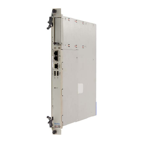
The EPC-23 is a PC/AT compatible CPU module in a very small form factor.
Based on the Intel486 SL chip set, this EPC has been designed to meet
stringent safety and low EMI standards (UL-1950). All front panel accessible
ports have filter networks for reduced EMI and increased ESD protection.
The EPC-23 processor module contains the following:
•A 25 MHz Intel486 SL processor
•Integrated math coprocessor
•8 Kbytes of integrated SRAM cache
•4 MBytes of DRAM memory expandable to 12 MBytes
•Keyboard interface
•1 standard 9-pin DTE serial port (COM1)
•1 RJ45 serial port (COM2)
•Time-of-day clock with user-replaceable battery
•Award BIOS
•EXM expansion interface (electrically similar to the 16-bit PC/AT ISA
bus)
WARNING!
DO NOT PLUG IN ANY CABLE OR CONNECTOR INTO THE FRONT PANE
CONNECTORS WHILE THE EPC-23 IS OPERATNG. THIS SYSTEM IS NO
T
DESIGNED FOR "HOT INSERTION" WHILE THE SYSTEM IS POWERED
UP, AND IS NOT DESIGNED TO WITHSTAND POTENTIAL DAMAGE THA
T
COULD ARISE FROM FLUCTUATIONS IN POWER. NEVER PLUG IN A
SERIAL OR PARALLEL DEVICE, KEYBOARD, TRANSCEIVER, OR OTHER
COMPONENT WHILE THE SYSTEM IS ON.
Page 1
Artisan Scientific - Quality Instrumentation ... Guaranteed | (888) 88-SOURCE | www.artisan-scientific.com

EPC-23 Hardware Reference
11
Specifications
The following table lists the environmental and electrical specifications of the
EPC-23.
Environmental
Temperature operating 0°to 60°C (* see below)
storage -40°to 125°C
Humidity operating 0 - 95% (non-condensing)
storage 0 - 95% (non-condensing)
Vibration operating .015" Peak to Peak 2.5g (max) 5-2000 Hz
storage .030" Peak to Peak 5g (max) 5-2000 Hz
Shock operating 30g 11 msec duration
storage 50g 11 msec duration
Electrical
Power maximum +5V @ 1.25 A
typical +5V @ 1.1 A
Table 1. EPC-23 Environmental and Electrical Specifications.
* Upper temperature limit degrades 2°C per 1000 ft. elevation. Maximum
elevation 10,000 ft.
See Appendix A for mechanical dimensions.
Page 2
Artisan Scientific - Quality Instrumentation ... Guaranteed | (888) 88-SOURCE | www.artisan-scientific.com

2. Installation and
Configuration 22
Before installing the EPC-23, unpack and inspect it for shipping damage.
DO NOT REMOVE THE MODULE FROM ITS ANTI-STATIC BAG
UNLESS YOU ARE IN A STATIC-FREE ENVIRONMENT.THE EPC-23,
LIKE MOST OTHER ELECTRONIC DEVICES,IS SUSCEPTIBLE TO ESD
DAMAGE.ESD DAMAGE IS NOT ALWAYS IMMEDIATELY OBVIOUS,
IN THAT IT CAN CAUSE A PARTIAL BREAKDOWN IN SEMICON-
DUCTOR DEVICES THAT MIGHT NOT IMMEDIATELY RESULT IN A
FAILURE.
ENSURE THAT THE INSTALLATION PROCESS AS DESCRIBED HEREIN
IS ALSO PERFORMED IN A STATIC-FREE ENVIRONMENT.
Insertion in an EXM Carrier
Insertion of the EPC-23 into an EXM carrier is straightforward. Remove a blank
EXM panel from the carrier (by unscrewing the thumbscrews) and insert the
EPC-23 into the card guides. Firmly press the EPC-23 front panel to ensure that the
module is properly seated in the subplane and secure it with the thumbscrews.
MAKE SURE THAT POWER TO YOUR SYSTEM IS OFF.THE EPC-23 IS
NOT DESIGNED TO BE INSERTED OR REMOVED FROM A LIVE
SYSTEM.
WHEN INSERTING THE EPC-23,AVOID TOUCHING THE CIRCUIT
BOARD,AND MAKE SURE THE ENVIRONMENT IS STATIC-FREE.
INSERT IT WITH ADEQUATE CONTINUOUS FORCE RATHER THAN
TAPPING OR HAMMERING ON IT.
Page 3
Artisan Scientific - Quality Instrumentation ... Guaranteed | (888) 88-SOURCE | www.artisan-scientific.com

EPC-23 Hardware Reference
Available Chassis
22
The EPC-23 fits several different chassis, including those listed below:
EMC-CC4
EMC-CH6D
EMC-CH8
EMC-CH10D
For example, the configuration might resemble the following:
RadiSys
CPU
RUN
RESET
EPC-23
PCMCIA
SUPER VGA
EXM-13AEXM-17EXM-18
LPT /COM
EXM-MX40
DISK
FLOPPY
CABLE
LPT
COM
ON/
REMOTE
C
O
M
2
C
O
M
1
K
B
R
E
M
O
T
E
EMC-PS50
AC
POWER ON
OVERTEMP
5VDC OK
!
FUSE TYPE: IEC PUB 127/I
1A 250V
CAUTION: FOR CON-
TINUEDPROTECTION
AGAINST RISK OF FIRE,
REPLACE ONLY WIT H SAME
TYPE AND RATING OF FUSE.
L
N
INPUT
85-264V
47-440
1.0A MAX
USE COPPER
CONDUCTORS
ONLY
S
T
B
Y
CORPORATION
LPT
COM
EMC-FDM
Figure 1. EMC-CH6D Chassis on an 8-Slot Backplane.
The EPC-23 can be inserted into any slot in the chassis. Typically, the far left slot is
selected. Note that the slot occupied by the EPC-23 has no unique configuration ID.
The settings used are identical to an unoccupied slot: FF 00 00.
Page 4
Artisan Scientific - Quality Instrumentation ... Guaranteed | (888) 88-SOURCE | www.artisan-scientific.com

Installation and Configuration
Power-On Screen Display
During the setup and configuration of the EPC-23, a graphics adapter and monitor are
required. 22
Whenever a hardware reset of the EPC occurs (power-on or front panel reset), the
system performs a power-on self-test (POST). If not set for "quick boot," the POST
displays information showing the status of the BIOS self-test if a monitor is attached
via a video adapter. If everything proceeds normally, the screen image displays
approximately as shown below.
486SL Modular BIOS V3.06.
Copyright (c) 1984-90 Award Software Inc.
Copyright 1992 RadiSys Corporation BIOS V3.06
TESTING INTERRUPT CONTROLLER #1 ......................... OK
TESTING INTERRUPT CONTROLLER #2 ......................... OK
TESTING CMOS BATTERY .................................... OK
TESTING CMOS CHECKSUM ................................... OK
SIZING SYSTEM MEMORY .............................. 640K FOUND
TESTING SYSTEM MEMORY ............................. 640K OK
CHECKING UNEXPECTED INTERRUPTS AND STUCK NMI ............ OK
TESTING PROTECTED MODE .................................. OK
SIZING EXPANSION MEMORY .......................... 3328K FOUND
TESTING MEMORY IN PROTECTED MODE ................. 4352K FOUND
TESTING PROCESSOR EXCEPTION INTERRUPTS .................. OK
TESTING ONBOARD SERIAL PORT #1 .......................... OK
TESTING ONBOARD SERIAL PORT #2 .......................... OK
RadiSys EPC Setup Program
Figure 2. EPC-23 POST Display.
If errors occur during the power-on self-test, the BIOS displays the error on the
appropriate line of the screen display and attempts to continue. For instance, if a
failure is discovered in COM1, the BIOS disables COM1, displays the error on the
line "TESTING ONBOARD SERIAL PORT #1 ....." and then continues as if the
error did not occur. It is important to watch the POST display to verify that no errors
occur.
If error messages are displayed during or after the POST display, see chapter 5,
Troubleshooting & Error Messages.
Page 5
Artisan Scientific - Quality Instrumentation ... Guaranteed | (888) 88-SOURCE | www.artisan-scientific.com

EPC-23 Hardware Reference
BIOS Setup Screen
22
The EPC-23 BIOS contains a setup function to display and alter the system
configuration. This configuration information is maintained in the EPC's battery-
backed CMOS RAM and is used by the BIOS to initialize the system hardware.
The setup function can be invoked any time after the POST completes and first clears
the screen. Simultaneously press the CTRL+ALT+ESC keys. This may be done
during system operation in most, but not all circumstances. Some programs that take
control of the keyboard at a low level, such as Microsoft Windows, cause this key
sequence to be interpreted differently, or not at all. It should always work, however,
when the DOS operating system prompt is shown on the screen. The main setup
screen displays similar to the following:
RadiSys EPC-23 CMOS Setup, BIOS V3.06
486SL, 4 MBytes memory
Date (mm/dd/yy) ............. 01/12/90
Time (hh:mm:ss) ............. 09:34:56
Configuration Errors ........ Halt on all errors
Diskette Drive A ............ 1.4M 3.5 inch
Diskette Drive B ............ None
Fixed Disk Drive C .... AT
Fixed Disk Drive D .... None
Com1: ........................ Enabled F2 = EXM Menu
Com2: ........................ Enabled F3 = Fixed Disk Menu
F10 = Save CMOS and EXM data
Cache ........................ Enabled ESC = Exit without saving
Quick Boot .................. Disabled ↑↓↵move between items
←→select values
Available EXM Slots ......... 8 slots
Figure 3. EXM Main Setup Screen.
Use the up and down cursor (arrow) keys to move from field to field. For most
fields, once the cursor is positioned at the field, pressing the left and right cursor
(arrow) keys will scroll through the available choices. Once the screen has been
changed to appear as you desire, press the F10 function key to save the changes in
battery-backed CMOS RAM. Then press the F5 function key to confirm the changes
and reboot, F1 to confirm changes but not reboot or ESC to ignore any changes and
exit. Each field is explained below.
Date and Time
Page 6
Artisan Scientific - Quality Instrumentation ... Guaranteed | (888) 88-SOURCE | www.artisan-scientific.com

EPC-23 Hardware Reference
These values are changed by moving to them and typing in the format shown.
22
Page 6
Artisan Scientific - Quality Instrumentation ... Guaranteed | (888) 88-SOURCE | www.artisan-scientific.com
Installation and Configuration
Configuration Errors
This field provides several choices about the situations under which the BIOS should
wait for user input if a configuration error is found. The selections are: 22
1) Halt on all errors
2) Ignore all errors
3) Ignore keyboard errors (allows operation without a keyboard)
4) Ignore disk errors
5) Ignore keyboard and disk errors
Diskette Drive
This field gives you several choices about the type of floppy disk drives installed as
the A and B drives. Toggle the entry to match the type of diskette drive(s) attached.
If no floppy drive is attached, select NONE for each diskette drive field.
Fixed Disk Drive
This display-only field shows the type of disk selected from the fixed disk menu.
Possible values are None, AT and EXM FLASH. To see the detailed characteristics
of the device or to change the device, use the F3 function key to go to the fixed disk
menu. See the section Fixed Disk Menu, page 10. EXM-16 SCSI and EXM-17
PCMCIA adapter users who will be booting from devices attached to these adapters
should set the Fixed Disk Drive type to None.
COM1/COM2
Toggling these fields enables or disables the COM1 and COM2 ports.
Cache
Toggling this field enables or disables the cache. The default is to enable the cache.
Quick Boot
This field enables or disables the quick boot option. When quick boot is disabled, the
system displays the results of the POST and runs the memory test. When quick boot
is enabled, the system runs the POST except the memory test and displays "Quick
boot enabled: disable through Setup screen to view."
Available EXM Slots
Page 7
Artisan Scientific - Quality Instrumentation ... Guaranteed | (888) 88-SOURCE | www.artisan-scientific.com
EPC-23 Hardware Reference
22
Enter the total number of EXM card cage connectors in the backplane (not the
number of slots in the chassis - count each EXM module or faceplate, then add two if
using the EMC-FDM) using the arrow keys to display the number. Note that in some
systems, the EXM-FDM floppy drive module consumes the two highest numbered
slots on the backplane, both of which must be included in the total number of
available slots.
As a "worst case" configuration example, if an eight-slot backplane is set for only
four slots, all EXMs above that fourth slot will not configure. (The only exception is
the video card, which auto-enables to allow for error recovery.) Continuing with this
example, the system would not boot if the boot device was located above the fourth
slot. Information would be cleared for the missing four slots, and would have to be
re-entered once the number of slots is corrected.
EXM Setup Screen
The EXM setup screen is used to configure EXM expansion modules in the system.
It is displayed by pressing the F2 function key from the main setup screen. The
EPC's battery-backed RAM holds identification and configuration information for the
number of available EXM slots entered in the EXM Main Setup Screen. The BIOS
displays the configuration information in hexadecimal format. The EXM Setup screen
for a system with an eight-slot backplane, a six-slot chassis, an
EMC-FDM in slots 6 and 7, and an EPC-23 in slot 0 might resemble the following:
RadiSys EPC-23 EXM Setup, System BIOS V3.06
486SL, 4 MBytes memory
Slot ID OB1 OB2
0 FF 00 00
1 ED 01 00 F10 = Save and return
2 7D 07 00 ESC = Return without saving
3 DB C1 00
4 D5 C1 00 ↑↓←→move between items
5 DE 00 39
6 7C FF FF
7 FF 00 00
ID is the unique EXM-ID number.
OB1 and OB2 are option bytes 1 and 2.
The option bytes interpretation is unique to each EXM-ID.
See the EXM user manuals for the semantics of the option bytes.
Figure 4. EXM Setup Screen.
Page 8
Artisan Scientific - Quality Instrumentation ... Guaranteed | (888) 88-SOURCE | www.artisan-scientific.com
Installation and Configuration
EXMs must be defined in this screen so the BIOS can correctly identify and initialize
each one at boot-up. Each EXM must be listed by slot number, ID and two option
bytes as defined below. 22
SLOT indicates the EXM card edge connector in which the EXM is
installed. Refer to Figure 5 below to determine which slot the EXM
occupies. Dashed lines indicate that not all slots are available in
some configurations.
ID is a hard-wired identification value. Each type of EXM has a
unique ID value.
OB1/OB2 are two "option" bytes of configuration information.
EXM Slots
0123456789
10 11
on the CH6D
This area used
by the EMC-FDM on the CH10D
This area used
by the EMC-FDM
Figure 5. EXM Slot Numbering.
All slots not occupied by an EXM module show an ID of FF, indicating that no EXM
is present. Note that the EPC-23 can be installed in any slot, and does not require any
ID or option byte information.
Consult the EXM manual for the correct configuration information for each EXM
expansion module installed.
After all EXMs have been configured, press F10 to save the data or ESC to ignore the
changes. In either case you return to the main setup screen.
Page 9
Artisan Scientific - Quality Instrumentation ... Guaranteed | (888) 88-SOURCE | www.artisan-scientific.com
EPC-23 Hardware Reference
Fixed Disk Menu
22
The Fixed Disk Menu is used to define the type of hard disk(s) installed in the
system. Enter the fixed disk menu screen by pressing the F3 function key from the
main setup screen.
The Fixed Disk Menu screen is similar to the following:
RadiSys EPC-23 Fixed Disk Menu, System BIOS V3.06
486SL, 4 MBytes memory
Fixed Disk Drive C: AT
Type 17 41 MBytes: 977 Cyls, 5 Heads, 17 Sectors
Landing Zone: 977 Precompensation: 300
Fixed Disk Drive D: None
F10 = Save and return
ESC = Return without saving
↑↓↵move between items
←→select values
Figure 6. Fixed Disk Menu Screen.
Use the up and down cursor keys (↑↓) to move between items. Use the left and right
cursor keys (←→) to scroll through the available choices for each item.
Disk type AT denotes IDE-compatible drives. You can scroll through a set of
numbered types; the physical configuration is displayed for each. Scroll through the
numeric drive types to find the one matching the characteristics of the hard drive
installed. Note that the RadiSys-supplied hard drive typically has a non-removable
sticker listing the drive type number (or user-defined parameters, if necessary - refer
to User-Definable Drive Types on page 11 for more information).
Choose disk type EXM Flash if you are using an EXM-2 flash disk. An EXM-2
flash disk can be made the boot device by making EXM Flash the drive C: type.
However, if Drive C: is EXM Flash, Drive D: must be set to None.
Choose None if there is no hard disk present or if you are using an EXM-16 SCSI or
an EXM-17 PCMCIA adapter as the boot device. This avoids the timeout period
used by the BIOS to conclude that there is no responding device.
Page 10
Artisan Scientific - Quality Instrumentation ... Guaranteed | (888) 88-SOURCE | www.artisan-scientific.com
Installation and Configuration
User-Definable Drive Types
22
If the correct AT disk type is not listed, the EPC provides user-editable drive types 48
and 49. Select either of these drive types. Use the TAB key (→| )or the left and right
cursor keys (←→) to move to the next (or previous) field. Note that the default
settings for MBytes, Cylinders, Heads, and Sectors is 1. MBytes is a display-only
field calculated by the BIOS. Move the cursor to each field (Cyls, Heads, and
Sectors) and type the value for that field. The information is listed on a non-
removable sticker attached to the hard drive. The BIOS allows use of the following
maximum values:
Cylinders 1023 Heads 63 Sectors 16
The hard disk you are using may have parameters larger than the allowable
maximum. If the number of cylinders for your drive is greater than the maximum
allowable number, you may have to use 1023 cylinders which will limit the usable
size of the drive. However, most IDE drives support universal translation mode. If
the drive you are using supports this mode and the actual parameters are greater than
the allowable maximum, divide the actual number of cylinders by 2 and multiply the
actual number of heads by 2. That is, each sector is addressed as an absolute
sequential sector number. Since the drive converts the sector data to an absolute
number, these "false" cylinder and head numbers will still allow the full capacity of
the drive to be used. The following example shows how this is done.
Actual
parameters
Conversion
factor Numbers
to Use
Cylinders 1350 divide by 2 675
Heads 5 multiply by
2 10
Sectors 32 (none) 32
Total
Sectors
216,000 216,000
Table 2. Fixed Disk Conversion Values.
After the fixed disk(s) have been configured, press F10 to save the data or ESC to
ignore the changes. In either case you return to the main setup screen. Follow the
instructions on the screen to save and exit or ignore changes and exit.
Page 11
Artisan Scientific - Quality Instrumentation ... Guaranteed | (888) 88-SOURCE | www.artisan-scientific.com

EPC-23 Hardware Reference
NOTES
22
Page 12
Artisan Scientific - Quality Instrumentation ... Guaranteed | (888) 88-SOURCE | www.artisan-scientific.com
Table of contents
Other RadiSys Control Unit manuals
Popular Control Unit manuals by other brands

GEM
GEM 711 Installation, operating and maintenance instructions

Evoqua
Evoqua WALLACE & TIERNAN SFC fieldbus manual

Siemens
Siemens GAMMA instabus Touch control TC5 manual

SMC Networks
SMC Networks EX245-FPS1 Operation manual

Johnson Controls
Johnson Controls H Series manual

Grandstream Networks
Grandstream Networks GBX20 Quick installation guide

Honeywell
Honeywell Class 500 installation instructions

Comelit
Comelit VEDOGSM4G Technical manual

Timotion
Timotion TDH1 user manual

Texas Instruments
Texas Instruments BoosterPack Educational Plug-in Module Mark II... user guide

Rodix
Rodix FEEDER CUBE FC-112 Plus manual

OceanServer Technology
OceanServer Technology OS5000 Series Faq