fakro ZWMA Parts list manual

Programming and usage instructions
adaptive module ZWMA
Contents
1 Safety rules..........................................................................................................................................................1
2 Description of ZWMA module ..........................................................................................................................3
3 Installation of ZWMA module ...........................................................................................................................4
4 Module programming ........................................................................................................................................5
4.1 Associating adapti e module to the Z-Wa e network (LEARN MODE function).....................................6
4.2 Associating de ice with ZWMA module (ASSOCIATE function)...........................................................7
4.3 De ice deleting from ZWMA adapti e module (DELETE function) ........................................................8
4.4 Return to default settings of the ZWMA adapti e module (DEFAULT function).....................................9
4.5 Remo ing the ZWMA adapti e module from the network.........................................................................9
4.6 Additional functions..................................................................................................................................10
4.6.1 Configuring the Z-Wa e network using the ZWMA adapti e module (INCLUDE function)..........10
4.6.2 Excluding a de ice from the Z-Wa e network using the ZWMA adapti e module (EXCLUDE
function) ......................................................................................................................................................11
5 Exemplary configuration of electrical accessories with the ZWMA module...................................................12
6 Technical parameters.........................................................................................................................................13
7 LED signalling of digital inputs........................................................................................................................13
8 WARRANTY....................................................................................................................................................14
13.11.21 NC825-GB 1/16 ©2013, FAKRO
GB

1 Safety rules
Read the instructions below carefully before proceeding to device installation so as to
avoid electric shock, injury etc.
CAUTI N!!!
The ZWMA module is powered by 230V alternating current. Electric shock hazard.
When installing the ZWMA module it is crucial to pay close attention to the following
recommendations:
●Installation should be performed by a qualified indi idual following manufacturer's
instructions.
●Connecting the module should be performed with power supply disconnected at all times.
●After unpacking, check module elements for any signs of mechanical damage.
●Before connecting the module, make sure that the power supply oltage corresponds with
that pro ided on the data plate.
●Plastic containers used for packing should be kept out of children's reach as thy may be a
potential source of hazard.
●The ZWMA module should be used for its intended purpose in agreement with its design.
The FAKRO Company shall not be held responsible for any consequences resulting from
improper module use.
●Any acti ities relating to cleaning, adjustment or disassembly of the module should be
preceded with its disconnection from the mains.
●The module should not be cleaned using any sol ent substances or open stream of water
(do not immerse in water).
●Any module repairs should be carried out by the manufacturer authorised ser ice.
●Electric cables supplying electricity to the source of power must ha e suitable area
(2x1mm2). The permissible cable length for the area specified abo e is 30 rm.
●The permissible length of cables plugged into digital inputs is 5 rm.
●The ZWMA adapti e module is intended for indoor installation.
13.11.21 NC825-GB 2/16 ©2013, FAKRO

2 Description of ZWMA module
ZWMA adapti e module fulfils the function of a controller and enables remote control of electrical
accessories compatible with Z-Wa e system, e.g. ZWS12 and ZWS230 actuators for operating FAKRO roof
windows. The module is equipped with four digital inputs, 3-contact (no.3 Figure 1) to which potential-free
signals from different external de ices are connected, e.g. thermostat, timer, KNX/EIB system, etc. The module
can operate up to 231 de ices simultaneously or in groups.
“SELECT” button (no. 3 – Figure 1) makes it possible to choose one from four channels (no.1 – Figure 1) to which
de ices such as ZWS12, ZWS230 actuators can be assigned. Channels correspond to the digital inputs (no. 8 –
Figure 1). De ices associated with the channel 1 are operated from the digital input 1, channel 2 - operated
from the digital input 2 etc...
ZWMA adapti e module is equipped with a two-way radio communication system Z-Wa e, which uses radio
frequency of 868,42 MHz.
Module controlling
De ices assigned to the channel are controlled as follows:
close – short (< 0,5s) short-circuit of contact 1-2 or pressing the button “down”
open- short (<0,5s) short-circuit of contact 2-3 or pressing the button “up”
stop - short-circuit (>1s) of contact 1-2-3
Multile el mode. Longer short-circuit (>0,5s) of contacts 1-2 or 2-3 will switch on de ice (open / close)
and opening of contacts – (stop).
13.11.21 NC825-GB 3/16 ©2013, FAKRO
Figure 1: ZWMA adaptive module`
1. Acti e channel and programming
signalling.
2. “In/Ex” functional button.
3.“SELECT” button for changing
acti e channel.
4. Open and close buttons.
5. Digital input signaling.
6. Electrical cable 2x0,75mm2
Power 230VAC 50Hz.
7. 12V DC power signaling.
8. Four 3-contact inputs
(potential-free)
````
2
C M
4
C M
2
3
4
5
6
1
87
3
C M
1
C M

3 nstallation of ZWMA module
The ZWMA module should be mounted onto a wall or other permanent element of the building by
means of screws dri en into cylindrical plugs inserted into openings drilled in the wall. In order to install the
ZWMA module, it is necessary to:
1. Take off the co er terminal of the casing.
2. Remount casing to the wall using screws.
3. Make all the necessary electric conections.
4. Screw the co er terminal of the casing .
13.11.21 NC825-GB 4/16 ©2013, FAKRO
Figure 2: ZWMA adaptive module casing
mounting
hole
mounting
hole
lower part
of module
casing
upper part
of module
casing
cover
terminal
plug
8cm
4,4cm
12cm

4 Module programming
In order to operate electric FAKRO accessories equipped with the Z-WAVE system by means of
the ZWMA adapti e module, it is necessary to:
1. Add the de ice to be operated by means of the module to the “Z-Wa e” system – see ZWP10 remote
control and ZWK10, ZWK1 keyboards manuals, chapter “Adding de ice to the network (INCLUDE
function)” or other controller working in the Z-Wa e system. If the de ice is already operated with one
of the controllers, proceed to section 2.
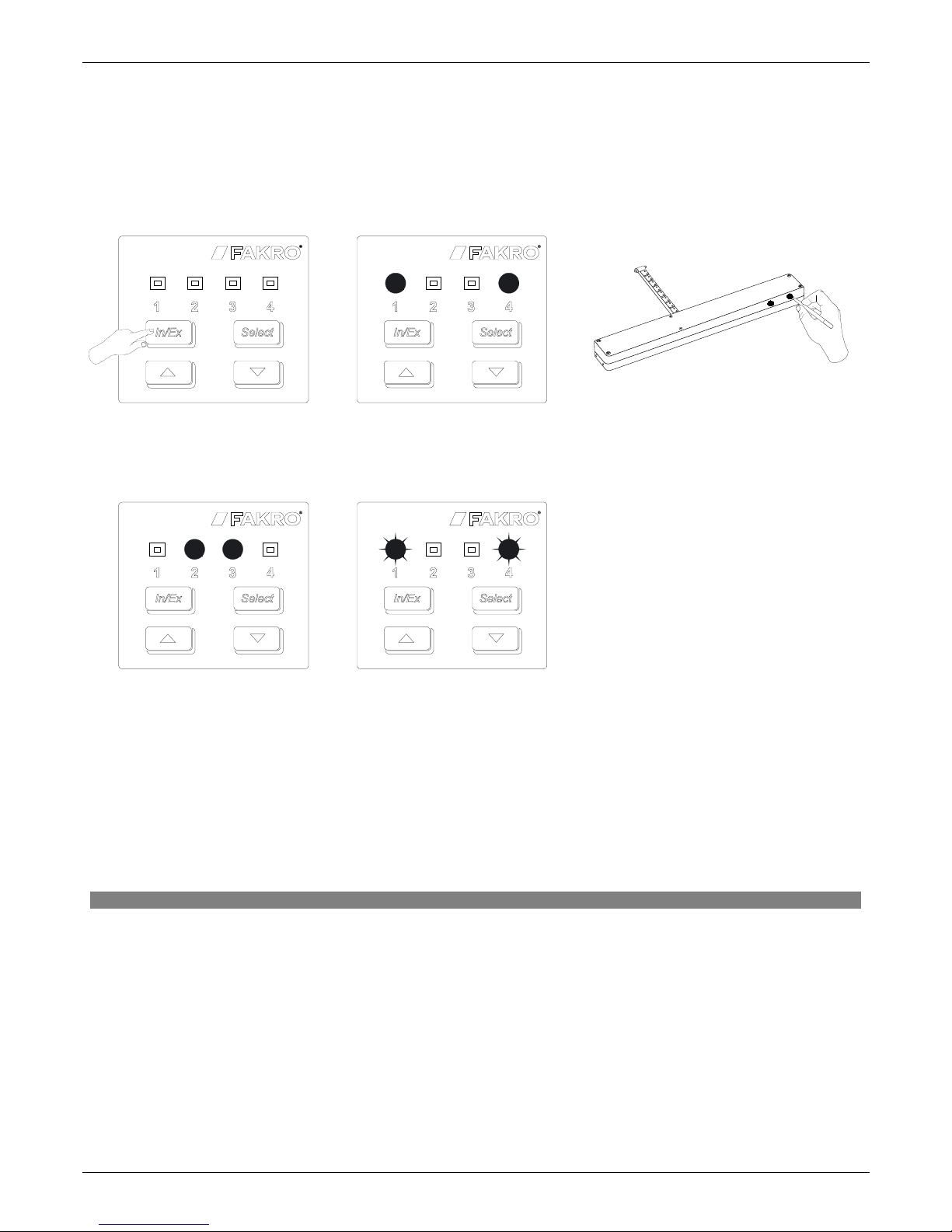
2. Add the module to the Z-Wa e network as a SECONDARY controller, chapter 4.1 (LEARN MODE
function).
and
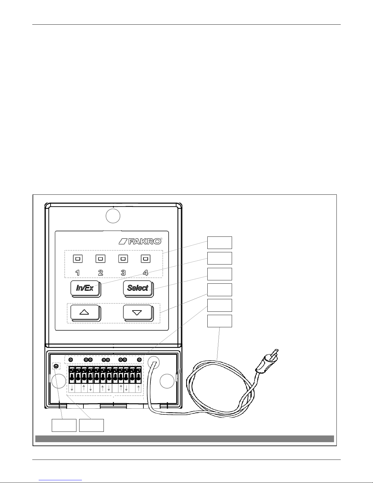
3. Associate the de ice with a selected channel in the module (No. 1, Figure 1) specifying the task to be
performed by it (chapter 4.2, ASSOCIATE function).
Note!!! Any de ice which is physically remo ed from the network (e.g. damaged) should be deleted from the
memory of the controller (PRIMARY, SECONDARY), that is first deleted from the pair of buttons (section
3.4) and then remo ed from the network (section 3.5). The correct implementation of the procedures is to
ensure optimal communication between de ices. Unplugging the de ice without remo ing it from the controller
memory will result in a prolonged reaction time to commands and faster depletion of the controller battery. If it
is necessary to remo e the damaged equipment, whose remo al from the controller memory is not possible, it is
desirable to reconfigure the whole network (all de ices). Start a new network configuration from restoring the
controller to the factory settings (DEFAULT function), then call the EXCLUDE function of de ices working
correctly and continue to the section 3, "Controller Programming".
Note!!! Mo ing the de ice within the network (e.g. socket module) it is recommended to delete it from the
controller memory (delete it from the pair of buttons first (section 3.4) and then remo e from the network
(section 3.5) and then add it again after installation in new place of work.
13.11.21 NC825-GB 5/16 ©2013, FAKRO

4.1 Associating adaptive module to the Z-Wave network (LEAR MODE function)
Associating the adapti e module (controller) results in its being categorized as SECONDARY. Associating
the module with the network consists in sending data to it from PRIMARY controller. The procedure of associating the
module with the network is presented in Figure 3. In order to assure the best possible communication within the network
and after each its modification (including or remo ing a de ice):
•associating another controller with the network should be performed after associating all de ices with the first
controller (“PRIMARY”),
•or performing LEARN MODE again on the “SECONDARY” controller already associated with the network.
*) Programming error results from failure to recei e any reply from the de ice which can be caused by:
•failure to enter LEARN MODE in the ZWMA module by pressing the “In/Ex” button three times until
the PRIMARY controller is signalling its readiness for adding a new de ice to the network:
•long distance between the controller and ZWMA module;
•the module is associated with another network and it is necessary to carry out the DEFAULT procedure
first.
13.11.21 NC825-GB 6/16 ©2013, FAKRO
Figure 3: Associating ZWMA module with Z-Wave network
3. Module is signaling start of
associating with the network (two
LEDs on as presented in the
drawing for app. 10 sec.).
1.Press “In/Ex” button once on the
PRIMARY controller, e.g.
ZWK15 keyboard.
2. Press “In/Ex” button three times in
ZWMA module which is to be added
to the network.
4. After few seconds, the module is signaling that associating with the
network is complete (LEDs on as presented in the drawing for app. 2-3 sec.).
5*. Programming error – two
LEDs flashing for app. 2-3 sec.
x3
Secondary
x1
Primary SecondaryPrimary
Primary Secondary Primary Secondary
Note!!! To control the de ices form the controller “Secondary”, perform the ASSOCIATE function (see section 3.2)
Note!!! In the newer ersion of a controller, interrupting any procedure is possible by pressing the “IN/EX” button. In the older
ersion, it is necessary to wait 10 seconds until the error is signalled by the controller or reset it by disconnecting the power
supply.

4.2 Associating device with ZWMA module (ASSOCIATE function)
Associating a de ice with the ZWMA module which has been already added to the Z-Wa e
network enables operating that de ice by means of a signal sent to the digital input in the module. The
procedure of de ice associating is presented in Figure 4.
*) Programming error results from failure to recei e any reply form the de ice and may be caused by:
•failure to press programming button within 10 seconds from the moment module is signalling its readiness for associating
a new de ice with a selected channel;
•long distance between the module and de ice being added;
•the de ice already belonging to the network other the module with which it is associated. It is necessary to associate the
module with the same network in which the de ice operates.
13.11.21 NC825-GB 7/16 ©2013, FAKRO
Figure : Device associating with selected input In ZWMA module
3. Module is signalling its
readiness for associating the
de ice with a selected channel
(three diodes on for 10 sec.).
5. The module is signaling that the
de ice has been associate successfully
(three diodes on for app. 2-3 sec.) In
order to check the correctness of
de ice operating proceed to section
4.2.1.
1.Using “SELECT” button
choose a channel through which
the de ice is to be operated.
6*. Programming error –
LEDs flashing for app. 2-3
sec.
2.Within 1 sec., press:
- “In/Ex” button once and then
- “˄” or “˅” buttons
4. Press “P” button on the de ice
and hold it for 0.5 sec. (see
De ice Programming Manual).
1
2 2
x1
x1 x1
lub
x1
>0,5Sec.
Note!!! In the newer ersion of a controller, interrupting any procedure is possible by pressing the “IN/EX” button. In the older
ersion, it is necessary to wait 10 seconds until the error is signalled by the controller or reset it by disconnecting the power supply.

4.3 Device deleting from ZWMA adaptive module (DELETE function)
This function remo es from the module's memory the de ice which has been associated with a
selected channel. It does not remo e the de ice from the “Z-Wa e” network. The procedure of deleting the
de ice from a gi en channel is presented in Figure 5.
*) Programming error results from failure to recei e any reply from the de ice and may be caused by:
•failure to press the programming button within 10 seconds from the module signalling its readiness to
delete the de ice;
•long distance between the module and de ice being deleted;
•the de ice belonging to network other than module.
Note!!! Any de ice which is physically remo ed from the network (e.g. damaged) should be deleted from the memory of the
controller (PRIMARY, SECONDARY), that is first deleted from the pair of buttons (section 3.4) and then remo ed from the network
(section 3.5). The correct implementation of the procedures is to ensure optimal communication between de ices. Unplugging the
de ice without remo ing it from the controller memory will result in a prolonged reaction time to commands and faster depletion of
the controller battery. If it is necessary to remo e the damaged equipment, whose remo al from the controller memory is not possible,
it is desirable to reconfigure the whole network (all de ices). Start a new network configuration from restoring the controller to the
factory settings (DEFAULT function), then call the EXCLUDE function of de ices working correctly and continue to the section 3,
"Controller Programming".
Note!!! Mo ing the de ice within the network (e.g. socket module) it is recommended to delete it from the controller memory
(delete it from the pair of buttons first (section 3.4) and then remo e from the network (section 3.5) and then add it again after
installation in new place of work.
13.11.21 NC825-GB 8/16 ©2013, FAKRO
Figure 5: Device deleting from ZWMA module channel
4. Press “P” button on the de ice and
hold it for 0.5 sec. (see De ice
Programming Manual)
2. Within 1.5 sec., press:
- “In/Ex” button twice and
- “˄” or “˅” button.
6*. Programming error –
LEDs flashing for app. 2-3
sec.).
1. Using “SELECT” button
choose a channel in the ZWMA
module, through which the
de ice to be deleted is operated.
5. The module is signaling that
the de ice has been deleted
successfully (three LEDs on for
app. 2-3 sec.).
3. The module is signalling
readiness for de ice deleting
(three LEDs on for 10 sec.).
1
2 2
x2
x1 x1
x1
>0,5Sec.
Note!!! In the newer ersion of a controller, interrupting any procedure is possible by pressing the “IN/EX” button. In the
older ersion, it is necessary to wait 10 seconds until the error is signalled by the controller or reset it by disconnecting the
power supply

4.4 Return to default settings of the ZWMA adaptive module (DEFAULT function)
Restoring default settings of the controller leads to the following information being deleted from its
memory:
•network, to which the module has been added;
•de ices associated with the ZWMA module.
The procedure of restoring default settings is described in Figure 6.
4.5 Removing the ZWMA adaptive module from the network
Remo ing the ZWMA module from the network consists in restoring default settings in this module.
13.11.21 NC825-GB 9/16 ©2013, FAKRO
Figure 6: Restoring default settings in ZWMA controller
Note!!! In the newer ersion of a controller, interrupting any procedure is possible by pressing the “IN/EX” button. In the older
ersion, it is necessary to wait 10 seconds until the error is signalled by the controller or reset it by disconnecting the power
supply.
1. Within 1.5 sec., press:
- “In/Ex” button twice and then
- „SELECT” button once.
2. The controller is signallling that default
settings ha e been restored – alternate flashing
of internal and external LEDs for app. 2-3 sec.
12x1
lub
x2

4.6 Additional functions
4.6.1 Configuring the Z-Wave network using the ZWMA adaptive module (I CLUDE function).
Adding a de ice to the “Z-Wa e” network is possibly only with the use of PRIMARY controller
(e.g. keyboard ZWK10, ZWK1, ZWP10, ZWPTV). The ZWMA module should be associated with the network
as SECONDARY. Howe er, there is a possibility of programming the module for the network as PRIMARY.
The procedure of de ice adding to the network with the use of the ZWMA module is presented in Figure 7.
*) Programming error results from the fact of not recei ing any response from the de ice and may be caused
by:
•failure to press the programming button within 10 seconds from the module signalling its readiness for
adding the de ice to the network;
•long distance between the module and the de ice being added;
•the module has been earlier associated with the network as “SECONDARY” – it is necessary to perform
DEFAULT procedure.
13.11.21 NC825-GB 10/16 ©2013, FAKRO
Figure 7: Removing device from the Z-Wave network using ZWMA adaptive module
4. The controller is signaling that
the de ice has been successfully
associated with the network (two
LEDs on for app. 2-3 sec.). For
operating accessories with the use
of the module, proceed to section
4.2.
5*. Programming error – two
external LEDs flashing for app.
2-3 sec.
2. The controller is signaling
its readiness for adding a new
de ice to the network (two
external LEDs on for 10 sec.).
3. Press “P” button on the de ice and
hold it more than 0.5 sec. (see De ice
Programming Manual).
1. Press “In/Ex” button once.
x1 x1
>0,5Sec.
Note!!! In the newer ersion of a controller, interrupting any procedure is possible by pressing the “IN/EX” button. In the older
ersion, it is necessary to wait 10 seconds until the error is signalled by the controller or reset it by disconnecting the power
supply.

4.6.2 Excluding a device from the Z-Wave network using the ZWMA adaptive module (EXCLUDE
function)
Excluding a de ice from the “Z-Wa e” network is possible only with the use of a PRIMARY controller
(e.g. ZWK10, ZWP10, ZWPTV). If the ZWMA module in the Z-Wa e network is marked as PRIMARY
(network configuration as per section 4.6.1), then de ices can be excluded only using that module. The
procedure of de ice excluding from the network with the use of the ZWMA module is presented in Figure 8.
*) Programming error results from the fact of not recei ing any response from the de ice and may be caused by:
•failure to press the programming button within 10 seconds from the module signalling its readiness to delete the
de ice;
•the de ice belonging to network other than module.
•the de ice is already assigned to another network or has not been assigned to any network. It is necessary to
perform EXCLUDE function on the de ice and then again perform INCLUDE and ASSOCIATE functions.
13.11.21 NC825-GB 11/16 ©2013, FAKRO
Figure 8: Excluding device from the Z-Wave network with the use of ZWMA adaptive module.
4. The controller is signaling that
the de ice has been successfully
excluded form the network (two
external LEDs on for app. 2-3 sec.).
5*. Programming error – two
middle LEDs flashing for app.
2-3 sec.
2. The controller is signaling
readiness for excluding the
de ice from the network (two
middle LEDs on for 10 sec.).
3. Press “P” button on the de ice and
hold it for 0.5 sec. (see De ice
Programming Manual).
1. Within 1 sec, press “In/Ex”
button twice.
x2 x1
>0,5Sec.
Note!!! In the newer ersion of a controller, interrupting any procedure is possible by pressing the “IN/EX” button. In the older
ersion, it is necessary to wait 10 seconds until the error is signalled by the controller or reset it by disconnecting the power
supply.

5 Exemplary configuration of electrical accessories with the ZWMA
module.
Blinds were connected to 15VDC (5) power supply and with the use of Primary (6) controller
added to the Z-Wa e network. In order to control the blind with the switch (4), also ZWMA module (1) was
added to the same Z-Wa e network with the use of LEARN MODE function (see section 4.1 of the manual) as
a Secondary controller. Re erse situation is also possible when the ZWMA module is a Primary controller, then
using additional controllers within the network is not required. Exemplary blind switch chosen by a client (4)
alternately short circuits the proper inputs (here up and down arrows) with appropriate COM input in ZWMA
module (as shown in Figure 9). Short circuit acti ates sending appropriate.
13.11.21 NC825-GB 12/16 ©2013, FAKRO
Figure 9: Adaptive module ZWMA as controller
1. Adapti e module ZWMA.
2. Four control inputs COM1 COM2 COM3 COM4 to which potential-free signals from different external de ices can be
connected, e.g. blind switch, rain sensor, thermostat, KNX/EIB system.
3. Short circuit – acti ation of potential-free input. ZWMA module sends command “close”, “open” or “stop” to the Z-Wa e
recei er (in this case: ARZ Z-Wa e roller shutter).
4. Blind switch.
5. Switched power supply 15 VDC (ZZ60 or ZZ60h) for three electrical accessories.
6. ZWP10 controller (optionally ZWK1, ZWK10, ZWG1 or ZWG3 keyboard).
15V DC
2
3x0,25mm2
3
1
1
COM
2
COM
3
COM
4
COM
4
2x0,75mm2
~230V AC
5
6

6 Technical parameters
Technical parameters
Power 230VAC
Worki g temperature (+5OC) to (40OC)
Worki g ra ge To 40 [m]
Worki g freque cy 868,42 MHz
Maximum cable le gth of the device plugged i to
digital or a alogue i put
5 rm
7 LED signalling of digital inputs
LEDs (Figure 1, no. 5) for digital inputs inform about acti ation of connected controllers..
LED for input:
COM1
–▲ lights at short-circuit of the contact responsible for sending command open
–▼ lights at short-circuit of the contact responsible for sending command close
–▼▲ light at short-circuits of the contacts responsible for sending command stop
COM 2, COM 3 and COM 4 analogously
13.11.21 NC825-GB 13/16 ©2013, FAKRO

8 WARRANTY
The manufacturer guarantees correct de ice functioning. It also undertakes to repair or replace the
de ice if its defects result from material or structural faults. The warranty period is 24 months from the
purchase date, fulfilling the following conditions:
●Installation has been performed by an authorised indi idual, as per manufacturer recommendations.
●Seals remain intact and no unauthorised structural changes ha e been made.
●The de ice has been used in accordance with its intended use as per user manual.
●Damage is not a result of improperly made electrical system or atmospheric phenomena.
●The manufacturer is not liable for damage which occurred as a result of improper use or mechanical
damage.
In case of failure, the de ice must be submitted for repair with a Warranty Card. Defects re ealed within the
warranty period will be remo ed free of charge no longer than 14 days after accepting the product for repair.
Warranty and post-warranty repairs are performed by the manufacturer i.e. FAKRO PP. Sp. z o.o.
Quality certificate:
De ice
Model............................................................................................................................................
Serial number...............................................................................................................................
Seller.............................................................................................................................................
Address...........................................................................................................................................
Date of purchase.............................................................................................................................
...............................................................................................................
Signature (stamp) of installing person
13.11.21 NC825-GB 14/16 ©2013, FAKRO

13.11.21 NC825-GB 15/16 ©2013, FAKRO

FAKRO PP Sp. z o.o.
ul. Węgierska 144A
33-300 Nowy Sącz
Polska
www.fakro.com
tel. +48 18 444 0 444
fax. +48 18 444 0 333
13.11.21 NC825-GB 16/16 ©2013, FAKRO
Other manuals for ZWMA
1
Table of contents
Other fakro Control Unit manuals
Popular Control Unit manuals by other brands

Thitronik
Thitronik Pro-finder Operating and installation instructions

Texas Instruments
Texas Instruments TSW14J56 user guide

System Sensor
System Sensor MDL3 Series Installation and maintenance instructions

Feig Electronic
Feig Electronic ID ISC.MRMU102-A user manual

Comelit
Comelit UT2010 Technical manual

Intellijel
Intellijel FSR 1U manual

GEA
GEA VARIVENT T R Series operating instructions

MFB
MFB DRUM-07 operating manual

Omnitron Systems Technology
Omnitron Systems Technology Omnitron iConverter 10/100M2 quick start guide

Atlas Copco
Atlas Copco Power MACS Product instructions

Ebyte
Ebyte E79-900DM2005S user manual

Siemens
Siemens SLT-1 installation instructions