Strongway STR866D User manual

HEAVY-DUTY GARDEN DUMP CART
OWNER’S MANUAL
WARNING:
Read carefully and understand all ASSEMBLY AND OPERATION
INSTRUCTIONS before operating. Failure to follow the safety rules and other
basic safety precautions may result in serious personal injury.
Item# 46533

Page of 122
Thank you very much for choosing a Strongway product! For future reference, please complete
the owner’s record below:
Model: _______________ Purchase Date: _______________
Save the receipt, warranty and these instructions. It is important that you read the entire manual
to become familiar with this product before you begin using it.
This cart is designed for certain applications only. The distributor cannot be responsible for
issues arising from modification. Do not modify this cart or use it for any application other than
that for which it was designed.
For technical questions please call 1-800-222-5381.
INTENDED USE
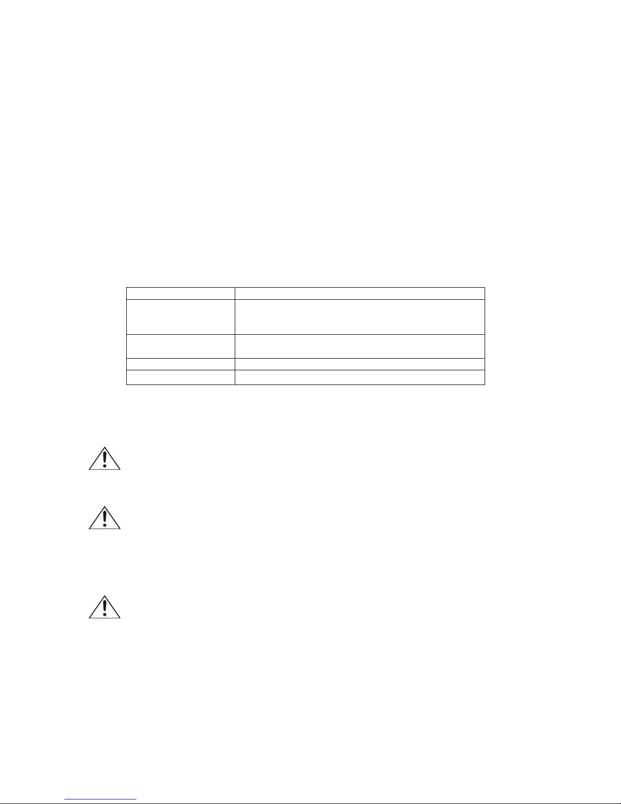
TECHNICAL SPECIFICATIONS
Item Description
Capacity Overall maximum 1,200 lbs. load capacity
Maximum 500 lbs. dumping load capacity when cart
is loaded.
Tires 13 inch Pneumatic Tires
Do not inflate the tires to more than 30 PSI.
Construction Poly bed with steel frame.
Dimensions 39.75 x 25.5 x 25.25
GENERAL SAFETY RULES
WARNING: Read and understand all instructions. Failure to follow all instructions listed
below may result in serious injury.
CAUTION: Do not allow persons to operate or assemble this heavy duty garden
dump cart until they have read this manual and have developed a thorough understanding of
how the heavy duty garden dump cart works.
WARNING: The warnings, cautions, and instructions discussed in this instruction
manual cannot cover all possible conditions or situations that could occur. It must be
understood by the operator that common sense and caution are factors which cannot be built into
this product, but must be supplied by the operator.
SAVE THESE INSTRUCTIONS

Page of 123
IMPORTANT SAFETY CONSIDERATIONS
Do not exceed loading capacity.
oMaximum load capacity: 1,200 lbs.
oMaximum dumping load capacity: 500 lbs.
Distribute load over the surface of the tray. Do not load items on the top edges of the tray.
Do not modify the cart in any way. Unauthorized modification may impair the function and/or
safety and could affect the life of the equipment. There are specific applications for which the
cart was designed.
This cart is not intended for highway use. Do not exceed 5 mph.
Do not use this cart for transporting passengers. Do not allow children to use this cart
without supervision. This cart is not a toy.
Do not inflate the tires to more than 30 PSI. Do not use the cart on surfaces or for
transporting objects that can cause damage to the pneumatic tires.
Always check of damaged or worn out parts before using the cart. Broken parts will affect
the operation. Replace or repair damaged or worn parts immediately.
Store idle the cart. When the cart is not in use, store it in a secure place out of the reach of
children. Inspect it for good working condition prior to storage and before re-use.

Page of 124
ASSEMBLY
1. Attach the front axle assembly (H) to the front frame (F) using four M8 x 20mm carriage bolts
(CC), four M8 lock nuts (JJ), and four M8 washers (FF). Attach the outer ends of the steering
linkage using two M6 x 20mm shoulder bolts (EE), M6 lock nuts (LL), and M6 washers (MM), as
shown in Fig. 1.
Hand tighten all bolts until after Step 2.
Fig. 1
F
H
CC
FF
MM
LL
JJ
EE
Hardware Used
CC
x 4
M8 Flat
Washer
JJ M8 Lock Nut x 4
M8 x 20mm
Carriage Bolt
x 4
LL
M6 Lock Nut x 2
MM
M6 Flat Washer x 2
FF
x 2
M6 x 20
Shoulder Bolt
EE
2. Attach the front struts (G) to connect the front axle assembly (H) to the front frame (F) using
four M8 x 20mm carriage bolts (CC), using four M8 lock nuts (JJ), and four M8 washers (FF), as
shown in Fig. 2. Tighten all bolts from Step 1 and Step 2 securely.
Fig. 2
Hardware Used
G
G
H
F
CC
CC
CC
CC
x 4
M8 Flat
Washer
JJ
JJ
FF
M8 Lock Nut x 4
M8 x 20mm
Carriage Bolt
x 4
FF
FF
JJ

Page of 125
3. Slide the rear struts (C) onto the ends of the rear axle assembly (E), as shown in Fig. 2.
Fig. 3
C
C
E
4. The rear axle assembly (E) attaches to the rear section of the rear frame (D). Double check the
rear frame (D) placement before assembling to the tub. The side holes on the rear frame (D) must
be towards the rear of the tray (A). Please reference the front and rear labels on the backside of the
rear frame (D) to confirm correct placement, as shown in Fig. 4, 5 and 6.
Fig. 4
FRONT
OF TRAY
D
A
E
Fig. 5 Fig. 6
NOTE: If the rear frame (D) is installed incorrectly, as shown in Fig. 6, the dump
lock assembly (B) installation in Step 6 will not engage when the cart tray (A) is
in the down position.
SIDE HOLE IN REAR
OF CENTER IS
Center
Line
Center
FRONT
OF TRAY
CORRECT
SIDE HOLE IN FRONT
OF CENTER IS
Center
Line
Center
FRONT
OF TRAY
INCORRECT
A
D

Page of 126
5. Attach the rear axle assembly (E) with the rear struts (C) and the rear frame (D) to the tray (A)
using five M8x25 carriage bolts (BB), one M8 x 20mm carriage bolt (CC), six M8 lock nuts (JJ), six
M11 washers (GG), and six M8 washers (FF), as shown in Fig. 7.
Use the one M8 x 20mm carriage bolt bolt (CC) in the front center location of the rear frame (D), as
shown in Fig. 7.
Fig. 7
Hole
Closer
to rear
of tray
Note correct
position of rear
frame as noted
in Step 4,
Figure 5.
Front
of tray
A
D
E
JJ
CC
GG
BB
FF
Hardware Used
x 5
x 1
x 6 x 6
M8 Flat
Washer
JJ
CC
M8 Lock Nut
x 6
GG M11 Flat
Washer
BB
FF
M8 x 20mm
Carriage Bolt
M8 x 25mm
Carriage Bolt

Page of 127
6. Attach the rear frame (D) to the front frame (F) using two internal button head bolts (DD), two M8
lock nuts (II), and two M8 washers (FF), as shown in Fig. 8.
Fig. 8
D
F
DD
DD
FF
JJ
Fig. 8
Hardware Used
x 2
M8 Flat Washer
JJ
FF
x 2
DD
M8 x 20mm
Internal Button
Head Bolt
x 2
M8 Lock Nut
7. Attach the dump lock assembly (B) to the tray (A) using three M8 x 20mm carriage bolts (CC),
three M8 lock nuts (JJ), three M11 washers (GG), and three M8 washers (FF), as shown in Fig. 9.
If the dump lock assembly (B) does not engage when you lower the cart tray (A), please double
check the placement of the rear frame (D) in Step 4.
A
BFF
CC
GG
JJ
Fig. 9
Hardware Used
x 3 x 3
x 3
M8 Flat Washer JJ M8 Lock Nut
FF
CC M8 x 20mm
Carriage Bolt x 3
GG M11 Flat
Washer

Page of 128
8. Attach the four wheels (I) by first placing the wheel spacers (HH) onto each axle, then the wheels
(I) and M12 flat washers (II), and M12 lock nuts (KK), as shown in Fig. 10.
I
HH
II
KK
Fig. 10
Hardware Used
X 4Wheel Spacer
HH
II M12 Flat Washer X 4
KK M12 Lock Nut X 4
9. Attach the handle (J) to the yoke on the front axle assembly (H) using the M8 x 60mm internal
button head (AA), M8 lock nut (JJ), and M8 washer (FF), as shown in Fig. 11.
Hardware Used
AA X 1M8 x 60mm
Internal Button
Head Bolt
x 1
x 1
M8 Flat Washer
JJ M8 Lock Nut
FF
Fig. 11
AA
FF
JJ
H
J

Page of 129
OPERATION
Distribute the load evenly over the surface of the tray.
Do not load items on the top edges of the tray.
USING THE SWIVEL HANDLE
1. Remove clips and cotter pins.
2. Rotate the handle and insert cotter pin. Secure by attaching the clip.
3. The second cotter pin is used to attach the handle to the trailer hitch.
USING THE DUMPING FEATURE
To use the dumping feature, pull the dumping release handle forward in order to release the tray
from the locking mechanism. Lift the release handle in order to rotate the tray upward into the
dumping position.
WARNING: To reduce risk of injury when dumping, ensure worksite is clear and free of hazards and
bystanders.
RETURNING THE TRAY TO THE LOWERED POSITION
Return the tray back to the lowered position and verify that the dumping release handle locks in
place. Avoid pinch points.

Page of 1210
MAINTENANCE
•Maintain your cart. It is recommended that the general condition of any cart be examined
before it is used. Keep your cart in good repair by adopting a program of conscientious repair
and maintenance. Have necessary repairs made by qualified service personnel.

Page of 1211
DIAGRAM & REPLACEMENT PARTS LIST
B
C
D
E
F
G
H
I
I
I
I
J
K
Part# Description Qty.
B Dump Lock Assembly 1
C Rear Strut 2
D Rear Frame 1
E Rear Axle Assembly 1
F Front Frame 1
G Front Strut 2
H Front Axle Assembly 1
I Tire 4
J Handle 1
K Hardware Kit 1
For replacement parts and technical questions, please call 1-800-222-5381.

Page of 1212
WARRANTY
1-year limited warranty
Distributed by
Northern Tool + Equipment Co., Inc.
Burnsville, Minnesota 55306
NorthernTool.com
Made in China
Table of contents
Other Strongway Outdoor Cart manuals

Strongway
Strongway 46530 User manual

Strongway
Strongway 46532 User manual

Strongway
Strongway 46435 User manual

Strongway
Strongway 52880 User manual

Strongway
Strongway 63760 User manual

Strongway
Strongway 64409 User manual

Strongway
Strongway 46376 User manual

Strongway
Strongway 53172 User manual

Strongway
Strongway 58077 User manual

Strongway
Strongway 46440 User manual