manuals.online logo
Brands
  1. Home
  2. •
  3. Brands
  4. •
  5. Stryker
  6. •
  7. Medical Equipment
  8. •
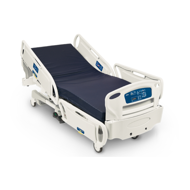
  9. Stryker S3 MEDSURG BED User manual

Stryker S3 MEDSURG BED User manual

SS33®® MMeeddSSuurrgg BBeedd wwiitthh SSttaayyPPuutt®® FFrraammee
OOppeerraattiioonnss MMaannuuaall
3002
Battery Backup / Zoom®
EN
3006-209-001 Rev AA.2 2021-12
SSyymmbboollss
Consult instructions for use
General warning
Caution
Non-ionizing radiation
Catalogue number

Serial number
 
For US Patents see www.stryker.com/patents
Manufacturer
Date of manufacture
Safe working load
Dangerous voltage
~
Alternating current
Direct current
Unit provides terminal for connection of a potential equalization conductor. The potential
equalization conductor provides direct connection between the unit and potential equalization
busbar of the electrical installation.
Protective earth ground
IIPPXX44 Protection from liquid splash
Type B applied part
87VL
Medical Equipment Classified by Underwriters Laboratories Inc. With Respect to Electric Shock,
Fire, and Mechanical Hazards Only in Accordance with ANSI/AAMI ES60601-1: 2005 and CAN/
CSA-C22.2 No. 60601-1:08.
3006-209-001 Rev AA.2 EN
In accordance with European Directive 2012/19/EU on Waste Electrical and Electronic
Equipment (WEEE) as amended, this symbol indicates that the product should be collected
separately for recycling. Do not dispose of as unsorted municipal waste. Contact local distributor
for disposal information. Ensure infected equipment is decontaminated prior to recycling.
Caution; electrostatic sensitive
ii
BBeedd Locator is connected
X
ii
BBeedd Locator is not connected
Network is connected
X
Network is not connected
This device complies with Part 15 of the FCC rules
EN 3006-209-001 Rev AA.2
TTaabbllee ooff CCoonntteennttss
Warning/Caution/Note Definition ..............................................................................................................................3
Summary of safety precautions ................................................................................................................................3
Introduction ...............................................................................................................................................................5
Product description .................................................................................................................................................5
Indications for use...................................................................................................................................................5
Indications for use for
ii
BBeedd WWiirreelleessss™....................................................................................................................5
Contraindications....................................................................................................................................................6
Expected service life ...............................................................................................................................................6
Specifications .........................................................................................................................................................6
Wi-Fi radio specifications (option) ........................................................................................................................7
System requirements and recommendations for
ii
BBeedd Wireless (option) ......................................................................8
i
Bed Server requirements for
i
Bed Wireless option ....................................................................................................8
Product illustration ..................................................................................................................................................9
Contact information...............................................................................................................................................10
Serial number location...........................................................................................................................................10
Setup.......................................................................................................................................................................11
Setting up nurse call communication (option) ..........................................................................................................11
Setting up the ZZoooomm motorized drive (option)..........................................................................................................12
Setting up
ii
BBeedd WWiirreelleessss (option)..........................................................................................................................13
Operation ................................................................................................................................................................14
Applying or releasing the brakes ............................................................................................................................14
Transporting the product with steer lock..................................................................................................................14
Transporting the product with the ZZoooomm motorized drive (option)..............................................................................15
Charging the battery (option)..................................................................................................................................16
Activating the CPR release ....................................................................................................................................17
Raising the lower leg section..................................................................................................................................17
Lowering the lower leg section ...............................................................................................................................18
Attaching a fracture frame......................................................................................................................................18
Securing a Foley bag to the Foley bag hooks ..........................................................................................................18
Securing the patient restraint straps .......................................................................................................................19
Raising the siderails ..............................................................................................................................................20
Lowering the siderails............................................................................................................................................20
Raising or lowering the two-stage permanently attached IV pole (option)...................................................................21
Positioning the removable IV pole (option) ..............................................................................................................22
Illuminating the room with the night light..................................................................................................................23
Activating nurse call communication (option)...........................................................................................................25
Replacing the nurse call backup battery (option)......................................................................................................25
Connecting peripheral equipment to the built-in 110 volt auxiliary power outlet (option)...............................................27
Operator control panel (outside siderail) .................................................................................................................27
Patient control panel (inside siderail) ......................................................................................................................29
Smart TV control panel (inside siderail) (option).......................................................................................................30
Footboard control panel - Bed controls ...................................................................................................................31
Footboard control panel - Lockouts.........................................................................................................................31
Footboard control panel - CChhaappeerroonnee bed exit (option)............................................................................................32
Arming or disarming CChhaappeerroonnee bed exit (option)...................................................................................................33
Footboard control panel - CChhaappeerroonnee bed exit with zone control (option) ..................................................................33
Arming or disarming CChhaappeerroonnee bed exit with zone control (option) .........................................................................34
Footboard LED indicators ......................................................................................................................................35
Footboard control panel - Scale..............................................................................................................................37
Weighing a patient............................................................................................................................................37
Setting the scale to zero....................................................................................................................................38
Menu display ........................................................................................................................................................39
Accessing functions and features with the menu display ..........................................................................................40
Menu display with
ii
BBeedd WWiirreelleessss (option) ..............................................................................................................41
Viewing the weight log...........................................................................................................................................41
3006-209-001 Rev AA.2 1 EN
Measuring weight gain or loss................................................................................................................................42
Changing equipment.............................................................................................................................................43
Changing the patient weight...................................................................................................................................44
Changing the scale units .......................................................................................................................................44
Changing the backlight intensity.............................................................................................................................45
Setting the alarm tones..........................................................................................................................................46
Setting the brake alarm .........................................................................................................................................46
Setting an audible
ii
BBeedd Awareness alarm...............................................................................................................46
Setting the
ii
BBeedd Awareness nurse call alarm ..........................................................................................................47
ii
BBeedd Awareness (option).......................................................................................................................................47
Configuring
ii
BBeedd Awareness.............................................................................................................................48
Acknowledging
ii
BBeedd Awareness status alerts.....................................................................................................48
Battery backup panel (option) ................................................................................................................................50
ZZoooomm motorized drive panel (option)......................................................................................................................51
Motion pendant with nurse call (option)...................................................................................................................52
Motion and communication pendant (option) ...........................................................................................................53
Infrared (IR) module (option)..................................................................................................................................54
ii
BBeedd LLooccaattoorr (option) ...........................................................................................................................................54
Accessories and parts ............................................................................................................................................56
Cleaning and disinfecting with wipes......................................................................................................................57
Cleaning..................................................................................................................................................................58
Disinfecting .............................................................................................................................................................59
Preventive maintenance .........................................................................................................................................60
FCC notification ......................................................................................................................................................62
EMC information .....................................................................................................................................................63
EN 2 3006-209-001 Rev AA.2
WWaarrnniinngg//CCaauuttiioonn//NNoottee DDeeffiinniittiioonn
The words WWAARRNNIINNGG,CCAAUUTTIIOONN, and NNOOTTEE carry special meanings and should be carefully reviewed.
WWAARRNNIINNGG
Alerts the reader about a situation which, if not avoided, could result in death or serious injury. It may also describe
potential serious adverse reactions and safety hazards.
CCAAUUTTIIOONN
Alerts the reader of a potentially hazardous situation which, if not avoided, may result in minor or moderate injury to the
user or patient or damage to the product or other property. This includes special care necessary for the safe and effective
use of the device and the care necessary to avoid damage to a device that may occur as a result of use or misuse.
NNoottee -- Provides special information to make maintenance easier or important instructions clearer.
SSuummmmaarryy ooff ssaaffeettyy pprreeccaauuttiioonnss
Always read and strictly follow the warnings and cautions listed on this page. Service only by qualified personnel.
WWAARRNNIINNGG
• Always plug the product directly into a grounded, hospital grade wall outlet. You can only achieve grounding reliability
when you use a hospital grade wall outlet. This product is equipped with a hospital-grade plug for protection against
electric shock hazard.
• Always use a Stryker supplied interface cable. Use of any other cable may cause the bed to not function as intended,
which may result in patient or user injury.
• Always associate or map the
ii
BBeedd LLooccaattoorr to the room or location to provide accurate location information. If you move
an
ii
BBeedd LLooccaattoorr after it has been installed and mapped, you must remap to the new room or location.
• Always apply the brakes when a patient is getting into or out of the product to avoid instability.
• Always apply the brakes when the patient is unattended.
• Do not apply the brakes to slow or stop the product while it is in motion.
• Always lock the siderails in the full up position with the sleep surface horizontal in the lowest position when you transport
the product with a patient.
• Always unplug the power cord before you transport the product.
• Always release the brakes before you transport the product. Do not transport the product with the brakes applied.
• Do not transport the product laterally after you apply the steer lock pedal. The product cannot swivel when you transport
with steer lock.
• Always use caution when transporting the product with the motorized drive wheel. Injury to the patient, operator, or
others, or damage to the product or equipment could occur if the product collides with an obstacle.
• Always use caution when transporting the product through halls, doors, and elevators. Damage to the siderails or other
parts of the product could occur if the product collides with walls or door frames.
• Always put the motorized drive wheel in the neutral position and release the brakes before transporting the product
manually. Do not transport the product manually with the motorized drive wheel in drive as the product will be difficult to
transport and could injure the operator.
• Always follow patient monitoring protocol to avoid patient injury. Power save mode is active after one hour on battery
power and no motion release switch activation. Bed exit, scale, and motion functions will not operate while the product is
in power save mode.
• Only use retractable traction or fracture frames. Failure to use a retractable frame may result in injury to the patient and/
or damage the equipment.
• Always set the siderail position to make sure that a patient is safely in the product.
• Always lock the operator control panel and patient control panel when the patient is unattended.
• Always keep the siderails outside of the oxygen tent.
• Only use hospital-grade electric equipment consuming 10A or less with the auxiliary power outlet (option). The use of
standard electric equipment may bring the current leakage to a level unacceptable for hospital equipment.
3006-209-001 Rev AA.2 3 EN
• Do not use the 110V auxiliary power outlet (option) for life sustaining equipment.
• Always lock the control panel when you leave the patient unattended.
• Always lock the patient control panel when the patient's condition requires extra safety measures.
• Do not use bed exit to replace patient monitoring protocol. Bed exit is intended only to aid in the detection of a patient
exiting the product.
• Do not use bed exit with patients who weigh less than 50 lb (23 kg).
• Do not use the scale system reading as a reference for medical treatment. The scale system assists only in the
monitoring of the patient’s weight variation.
• Do not set the scale to zero or weigh the patient when a support surface therapy is active. Motion from the support
surface functions may adversely affect the scale system performance.
• Do not use
ii
BBeedd Awareness to replace your patient monitoring protocol.
• Do not use
ii
BBeedd Awareness as a lock indicator for siderails.
ii
BBeedd Awareness only detects the position of the siderails.
CCAAUUTTIIOONN
• Improper usage of the product can cause injury to the patient or operator. Operate the product only as described in this
manual.
• Do not modify the product or any components of the product. Modifying the product can cause unpredictable operation
resulting in injury to patient or operator. Modifying the product also voids its warranty.
• Always make sure that product operation is not affected when you attach equipment to the product.
• Always make sure that all persons and equipment are away from the area below and around the Fowler before you
activate the CPR release. The CPR release is for emergency use only.
• Always follow hospital protocol to determine the use of restraint straps and restraint strap locations. Stryker is not
responsible for the type or use of restraint straps on any Stryker product.
• Do not load the IV pole above the safe working load of 40 lb (18 kg).
• Always raise the siderails when the litter is in its full down position. This prevents the scale system from weighing a
patient inaccurately.
• Always make sure that the siderails are locked before you arm
ii
BBeedd Awareness.
• Always make sure that you set the desired product parameters before you arm
ii
BBeedd Awareness.
• Do not use accessories that cover the footboard LED light bars.
• Do not clean, disinfect, service, or perform maintenance while the product is in use.
• Always unplug the power cord from the wall outlet when large spills occur near the circuit boards, cables, and motors.
Remove the patient from the product, clean up the fluid, and inspect the product. Fluids can cause unpredictable
operation and decreased functionality of any electrical product. Do not return the product to service until it is completely
dry and you have tested for safe operation.
• Always clean VVeellccrroo®® after each use. Saturate VVeellccrroo with disinfectant and allow disinfectant to evaporate. Appropriate
disinfectant for nylon VVeellccrroo should be determined by the hospital.
• Always wipe down with clean water (or 70% isopropyl alcohol, if using VViirreexx® TB) and dry each product after
disinfecting. Some disinfectants are corrosive in nature and may cause damage to the product. If you do not rinse and
dry the product, you may leave a corrosive residue on the surface of the product. This corrosive residue could cause
premature degradation of critical components. Failure to follow these disinfecting instructions may void your warranty.
• Always clean VVeellccrroo® after each use. Saturate VVeellccrroo with disinfectant and allow disinfectant to evaporate. Appropriate
disinfectant for nylon VVeellccrroo should be determined by the hospital.
• Do not use quaternary disinfectants formulated with glycol ethers.
EN 4 3006-209-001 Rev AA.2
IInnttrroodduuccttiioonn
This manual assists you with the operation or maintenance of your Stryker product. Read this manual before operating or
maintaining this product. Set methods and procedures to educate and train your staff on the safe operation or maintenance
of this product.
CCAAUUTTIIOONN
• Improper usage of the product can cause injury to the patient or operator. Operate the product only as described in this
manual.
• Do not modify the product or any components of the product. Modifying the product can cause unpredictable operation
resulting in injury to patient or operator. Modifying the product also voids its warranty.
NNoottee
• This manual is a permanent part of the product and should remain with the product even if the product is sold.
• Stryker continually seeks advancements in product design and quality. This manual contains the most current product
information available at the time of printing. There may be minor discrepancies between your product and this manual. If
you have any questions, contact Stryker Customer Service or Technical Support at 1-800-327-0770.
PPrroodduucctt ddeessccrriippttiioonn
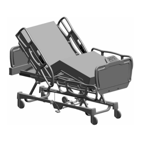
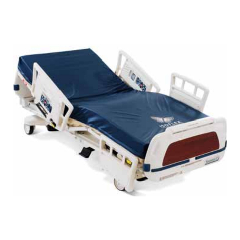
The 3002 SS33® MedSurg bed has Fowler, Gatch and lift articulation capabilities that aid in the adjustment of surface
contour, angle, and height. The product offers various options outlined in the product operations manual, including but not
limited to
ii
BBeedd®AAwwaarreenneessss™, scale, 110V auxiliary outlet (option), IV pole, and defibrillator tray.
ii
BBeedd AAwwaarreenneessss allows
operators to set various bed parameters to monitor bed positioning. Alerts inform operators to patient movement within a
specific zone(s) on a patient surface. The product may be equipped with an integrated scale intended to weigh the patient in
bed. Both
ii
BBeedd AAwwaarreenneessss and CChhaappeerroonnee® bed exit systems provide both visual and audible alerts.
IInnddiiccaattiioonnss ffoorr uussee
The 3002 SS33 MedSurg bed is intended to support and transport patients within the Med/Surg and Critical Care hospital
environments. The 3002 SS33 MedSurg bed is typically used in pre-op, post-op, and recovery areas of hospital facilities. The
intended user for this product is both healthcare providers (HCP), such as, nurses, nurses’ aides, medical doctors, and
human patients. Lockout features may limit patient accessible controls. Use this product with a patient sleep surface. The
scale output is not intended to be used to determine diagnosis or treatment.
The intended patient population for the 3002 SS33 MedSurg bed includes:
• Patients above 50 lb with a safe working load of 500 lb (227 kg)
• Patients at least 2 years of age
• Patients less than 84 in. (213.4 cm) without a bed extender or 96 in. (243.8 cm) with a bed extender
The product is not intended to support more than one individual at a time.
IInnddiiccaattiioonnss ffoorr uussee ffoorr
ii
BBeedd WWiirreelleessss™™
The intended use for
ii
BBeedd WWiirreelleessss (with
ii
BBeedd AAwwaarreenneessss system) is to assist clinical staff to monitor bed parameters on
specific Stryker beds. The desired bed parameters are set by operators at the bedside.
ii
BBeedd WWiirreelleessss is only intended for
use with specifically enabled Stryker beds that have been verified and validated with
ii
BBeedd WWiirreelleessss, and is not intended to
provide bed status information for non-Stryker beds.
ii
BBeedd WWiirreelleessss is not intended to communicate any patient status
information, nor to permanently store any type of data.
ii
BBeedd Wireless with
ii
BBeedd AAwwaarreenneessss system is not intended to
provide automated treatment decisions or as a substitute for professional healthcare judgment.
ii
BBeedd WWiirreelleessss with
ii
BBeedd
AAwwaarreenneessss system is not a replacement or substitute for vital signs monitoring or alert equipment. All patient medical
diagnosis and treatment are to be performed under direct supervision and oversight of an appropriate healthcare
professional.
3006-209-001 Rev AA.2 5 EN
CCoonnttrraaiinnddiiccaattiioonnss
None known.
EExxppeecctteedd sseerrvviiccee lliiffee
The 3002 SS33 MedSurg bed has a ten year expected service life under normal use conditions and with appropriate periodic
maintenance.
The optional motion/nurse call pendant has a two year expected service life under normal use conditions.
The optional motion/nurse call/SmartTV pendant has a two year expected service life under normal use conditions.
The optional
ii
BBeedd Wireless components have a three year expected service life under normal use conditions.
SSppeecciiffiiccaattiioonnss
Safe working load
NNoottee -- Safe working load indicates the sum of the
occupant and accessory weight.
500 lb 227 kg
Product weight
Standard bed 510 lb 231 kg
With ZZoooomm® (option) 692 lb 314 kg
Scale system capacity (option), loads weighing up to: 500 lb 227 kg
Scale system accuracy (option)
± 3 lb for patients weighing 50 to 100 lb
± 3% of the total patient weight for patients
weighing 100 to 500 lb
Overall length and width Siderails up 93 in. x 42.5 in. 236.2 cm x 105.4 cm
Siderails down 93 in. x 39 in. 236.2 cm x 99.1 cm
Patient sleep surface 84 in. x 35 in. 213.4 cm x 88.9 cm
Bed height to top of seat litter with 6” casters
Standard bed 16 in. to 30 in. 40.6 cm to 76.2 cm
With battery backup
(option) / ZZoooomm
(option)
19.5 in. to 30 in. 49.5 cm to 76.2 cm
Litter platform to top of siderail
(full up)
Head end siderail 15 in. 38.1 cm
Foot end siderail 15.5 in. 39.37 cm
Space between siderails (full up) 2.5 in. 5.72 cm
Gatch position 0° to 40° ± 5°
Fowler position 0° to 60°
Trendelenburg and Reverse Trendelenburg +12° ± 1° to -10° ± 1°
Electrical requirements - all electrical requirements meet UL 2601
specifications 115 VAC, 60 Hz, 8 A
EN 6 3006-209-001 Rev AA.2
Outlet (option) 110 VAC, 60 Hz, 10 A
Battery voltage
(2) 12V 31Ah - Battery backup (option) /
ZZoooomm (option) (gel cell battery)
(1) 9V - Nurse call (option) (alkaline battery)
CCoommppaattiibbllee mmaattttrreessss
Thickness Width Length ILD
6 in. 15.2 cm >= 35 in. >= 88.9 cm >= 84 in. >= 213.4 cm 80 lb 36.3
NNoottee -- These mattress specifications comply with HBSW and IEC specifications.
Stryker reserves the right to change specifications without notice.
Specifications listed are approximate and may vary slightly from product to product or by power supply fluctuations.
EEnnvviirroonnmmeennttaall ccoonnddiittiioonnss OOppeerraattiioonn SSttoorraaggee aanndd ttrraannssppoorrttaattiioonn
Ambient temperature
104 °F
(40 °C)
50 °F
(10 °C)
140 °F
(60 °C)
-22 °F
(-30 °C)
Relative humidity (non-condensing)
75%
30%
95%
10%
Atmospheric pressure
1060 hPa
700 hPa
1060 hPa
500 hPa
WWii--FFii rraaddiioo ssppeecciiffiiccaattiioonnss ((ooppttiioonn))
Manufacturer model Silex SX-SDMAN-2830S
Chipset AR6233X, Core chip AR6003X CSP (Qualcomm Atheros)
IEEE 802.11 a/b/g/n
RF bands 2.4 GHz, 5 GHz
Encryption AES and TKIP
(TKIP is not supported with WPA2)
Authentication WPA Personal / Enterprise and WPA2 Personal /
Enterprise
802.1X PEAP-MSCHAP - V2
Client certificates Cannot accept or upload certificates
Supported data rates 802.11b/g: 1-54 Mbps
802.11a: 6-54 Mbps
802.11n: MCS0-6
Channel plan 2.4 GHz: All Channels Supported
5 GHz: All Channels Supported
(Recommend against using DFS and ISM Channels)
Other Leverage hospital SSID
3006-209-001 Rev AA.2 7 EN
SSyysstteemm rreeqquuiirreemmeennttss aanndd rreeccoommmmeennddaattiioonnss ffoorr
ii
BBeedd WWiirreelleessss ((ooppttiioonn))
To implement
ii
BBeedd Wireless, follow these requirements for hardware, software, and communication, product specifications,
required settings, and recommendations.
NNoottee -- If minimum system requirements are not met, system performance will be impacted.
ii
BBeedd SSeerrvveerr rreeqquuiirreemmeennttss ffoorr
ii
BBeedd WWiirreelleessss ooppttiioonn
The following tables describes the server hardware and software requirements for
ii
BBeedd Wireless:
HHaarrddwwaarree rreeqquuiirreemmeennttss
CCaappaacciittyy RReeqquuiirreemmeenntt
1-300 connected devices 2.x GHz processor or better with 4 cores
Memory: 8 GB RAM
Hard drive: 150 GB
301-600 connected devices 2.x GHz processor or better with 8 cores
Memory: 16 GB RAM
Hard drive: 150 GB
601-800 connected devices 2.x GHz processor or better with 16 cores
Memory: 32 GB RAM
Hard drive: 150 GB
801-1000 connected devices 2.x GHz processor or better with 24 cores
Memory: 32 GB RAM
Hard drive: 150 GB
1001-1300 connected devices 2.x GHz processor or better with 32 cores
Memory: 64 GB RAM
Hard drive: 150 GB
1300+ connected devices Add additional core per 50 devices
Two server environments are recommended for the
ii
BBeedd Wireless:
TEST and PROD
The
ii
BBeedd Wireless is supported in either physical or virtual environments
SSooffttwwaarree aanndd sseettuupp rreeqquuiirreemmeennttss
Operating system Microsoft Windows Server 2008 R2 / 2012 R2
Server roles Web server (IIS)
Roles services
- Application development
• ASP.NET
• ASP
Server features .NET Framework 3.5.1
Other All current Microsoft priority updates and optional update
.NET Framework 4.5
EN 8 3006-209-001 Rev AA.2
SSeeccuurriittyy rreeqquuiirreemmeennttss
Credentials Administrator account on the server machine for installation
and configuration
Remote access Provide remote access to the
ii
BBeedd Server machines. For
example, VPN, Citrix
NNoottee -- Backups of the system or a Disaster Recovery Plan is the responsibility of the customer.
PPrroodduucctt iilllluussttrraattiioonn
B
G
O
J
K
T
Q
R
I
H
SA
E
C
M
P
I
F
D
N
L
FFiigguurree 11 –– MMooddeell 33000022 SS33 MMeeddSSuurrgg bbeedd
A110 VAC outlet (option) KIsolated Foley bag hooks
BBBaacckkSSmmaarrtt®® brake pedal L Mattress retainer
C Caster M Motion interrupt pan
D CPR release handle N Night light
EFoley bag hooks OBBaacckkSSmmaarrtt operator control panel
3006-209-001 Rev AA.2 9 EN
F Footboard P Patient control panel
GBBaacckkSSmmaarrtt footboard control panel QSiderail release handle
H Headboard R BBaacckkSSmmaarrtt siderails
I
ii
BBeedd Awareness LED light bar SBBaacckkSSmmaarrtt steer pedal
JIntegrated pump rack TSupport surface
CCoonnttaacctt iinnffoorrmmaattiioonn
Contact Stryker Customer Service or Technical Support at: 1-800-327-0770.
Stryker Medical
3800 E. Centre Avenue
Portage, MI 49002
USA
To view your operations or maintenance manual online, see https://techweb.stryker.com/.
Have the serial number (A) of your Stryker product available when calling Stryker Customer Service or Technical Support.
Include the serial number in all written communication.
SSeerriiaall nnuummbbeerr llooccaattiioonn
You can find the serial number (A) above the power cord behind the headboard (Figure 2).
A
FFiigguurree 22 –– SSeerriiaall nnuummbbeerr llooccaattiioonn
EN 10 3006-209-001 Rev AA.2
SSeettuupp
WWAARRNNIINNGG -- Always plug the product directly into a grounded, hospital grade wall outlet. You can only achieve grounding
reliability when you use a hospital grade wall outlet. This product is equipped with a hospital-grade plug for protection
against electric shock hazard.
To setup and test the functionality of the product:
1. Plug the product into a grounded, hospital grade wall outlet and make sure that the power button LED light at the foot
end of the product comes on.
2. Check that the siderails raise, lower, lock in the up position, lock in the intermediate position when lowered and store
smoothly.
3. Check that all four casters lock when the brake is applied.
NNoottee -- Check that the BBrraakkee LED located on the outside of the head end siderails (
Operator control panel (outside
siderail)
(page 27)) and on the footboard control panel (Figure 27) blink when the brakes are released.
4. Raise the Fowler (head of bed) up to approximately 60°. Squeeze the CPR release handle and make sure that the back
will drop with minimal effort.
5. Perform each function on the footboard control panel to make sure that each function is working.
6. Perform each function on both head end siderails to make sure that each function is working.
7. Activate the motion stop system to make sure that it is working. Press the BBeedd hheeiigghhtt ddoowwnn button to lower the litter. As
the litter lowers, push up on the motion interrupt pan under the litter and make sure that the downward motion stops.
Release the pan and allow the downward motion to continue.
NNoottee -- The product’s upward motion or other functions are not disrupted by the motion stop system
SSeettttiinngg uupp nnuurrssee ccaallll ccoommmmuunniiccaattiioonn ((ooppttiioonn))
WWAARRNNIINNGG -- Always use a Stryker supplied interface cable. Use of any other cable may cause the bed to not function as
intended, which may result in patient or user injury.
To setup nurse call communication:
1. Plug the interface cable into the 37-pin connector in the litter frame at the head end of the product (B) (Figure 3) and into
the applicable connection (patient station, head wall, or docker station).
NNoottee -- Only connect the 37-pin connector to the head wall output configuration (B) (Figure 3) or product
Communications Tester (sold separately).
2. Test the interface cable to verify connectivity.
3. Plug the power cord into the wall outlet.
4. Push in the pendant port switch and turn the switch to the on position (90° clockwise) (A) (Figure 3).
5. Press the NNuurrssee ccaallll button (see
Operator control panel (outside siderail)
(page 27)) to verify the connection between
the product’s nurse call signal and the hospital’s nurse call system.
NNoottee -- A 9V battery powers the nurse call signal when the product is unplugged. If the product is unplugged from a wall
outlet while the nurse call pendant port switch is set to the on position, the 9V battery will begin to drain (
Replacing the
nurse call backup battery (option)
(page 25)).
To activate the optional nurse call communication, see
Activating nurse call communication (option)
(page 25).
3006-209-001 Rev AA.2 11 EN
A
B
FFiigguurree 33 –– NNuurrssee ccaallll ppeennddaanntt ppoorrtt aanndd 3377--ppiinn ccoonnnneeccttoorr
SSeettttiinngg uupp tthhee ZZoooomm mmoottoorriizzeedd ddrriivvee ((ooppttiioonn))
To setup the ZZoooomm motorized drive:
1. Plug the product into a grounded, hospital grade wall outlet. The 12V batteries that provide power to the drive wheel and
the backup power to the unit functions, will charge whenever the power cord is plugged into a wall outlet.
NNoottee -- The batteries will have a full charge within approximately 10 hours.
2. Unplug the power cord from the wall outlet. Push the battery power switch located on the lower left corner of the head
end to the OONN position (Figure 6).
NNoottee -- Check that each function works on the footboard control panel and the head end siderails (see
Setup
(page 11)).
3. With the battery power switch on and the brakes applied, make sure that the RReelleeaassee bbrraakkeess LED illuminates on the
head end control panel (
ZZoooomm motorized drive panel (option)
(page 51)).
4. With the battery power switch on and the drive wheel in the neutral position, make sure that the EEnnggaaggee ddrriivvee wwhheeeell
LED illuminates on the head end control panel (
ZZoooomm motorized drive panel (option)
(page 51)).
5. Perform the drive wheel operation (
Transporting the product with the ZZoooomm motorized drive (option)
(page 15)) to make
sure that each function is working.
Contact Stryker Technical Support with any setup questions (
Contact information
(page 10)).
EN 12 3006-209-001 Rev AA.2
SSeettttiinngg uupp
ii
BBeedd WWiirreelleessss ((ooppttiioonn))
WWAARRNNIINNGG -- Always associate or map the
ii
BBeedd LLooccaattoorr to the room or location to provide accurate location information. If
you move an
ii
BBeedd LLooccaattoorr after it has been installed and mapped, you must remap to the new room or location.
To setup
ii
BBeedd WWiirreelleessss:
Install the 5212
ii
BBeedd LLooccaattoorr™ on the wall at the head end of the product. The
ii
BBeedd LLooccaattoorr communicates with the IR
module that is installed in your product. For detailed instructions about how to mount the
ii
BBeedd LLooccaattoorr, see the instructions
for use that was included with your
ii
BBeedd LLooccaattoorr installation kit.
Contact Stryker Technical Support with any installation questions (
Contact information
(page 10)).
NNoottee -- You must load the wireless connection settings before the device will communicate with the
ii
BBeedd Server application.
See the
ii
BBeedd Server Installation and Configuration manual.
3006-209-001 Rev AA.2 13 EN
OOppeerraattiioonn
AAppppllyyiinngg oorr rreelleeaassiinngg tthhee bbrraakkeess
WWAARRNNIINNGG
• Always apply the brakes when a patient is getting into or out of the product to avoid instability.
• Always apply the brakes when the patient is unattended.
• Do not apply the brakes to slow or stop the product while it is in motion.
You can find the brake pedals on both the left and right sides of the product.
To apply the brakes, depress the brake pedal down toward the floor.
To release the brakes, depress the brake pedal down toward the floor again.
NNoottee -- The BBrraakkee LED on the footboard control panel (
Footboard LED indicators
(page 35)) illuminates when you apply the
brakes. You can also set an audible alarm in the advanced menu (
Setting the brake alarm
(page 46)).
FFiigguurree 44 –– AAppppllyyiinngg oorr rreelleeaassiinngg tthhee bbrraakkeess
TTrraannssppoorrttiinngg tthhee pprroodduucctt wwiitthh sstteeeerr lloocckk
WWAARRNNIINNGG
• Always lock the siderails in the full up position with the sleep surface horizontal in the lowest position when you transport
the product with a patient.
• Always unplug the power cord before you transport the product.
• Always release the brakes before you transport the product. Do not transport the product with the brakes applied.
• Do not transport the product laterally after you apply the steer lock pedal. The product cannot swivel when you transport
with steer lock.
Steer lock guides the product along a straight line during transport and pivots the product around corners. The steer lock
pedal locks the right side caster on the foot end. The steer lock pedal is located at the head end of the product.
To transport with steer lock:
1. Align the wheels to face the direction of transport.
2. Push the steer lock pedal to on (Figure 5).
To release steer lock, push the steer lock pedal to off (Figure 5).
NNoottee -- To move the product in any direction, including laterally, release the steer lock pedal.
EN 14 3006-209-001 Rev AA.2
FFiigguurree 55 –– AAppppllyyiinngg oorr rreelleeaassiinngg sstteeeerr lloocckk
TTrraannssppoorrttiinngg tthhee pprroodduucctt wwiitthh tthhee ZZoooomm mmoottoorriizzeedd ddrriivvee ((ooppttiioonn))
WWAARRNNIINNGG
• Always use caution when transporting the product with the motorized drive wheel. Injury to the patient, operator, or
others, or damage to the product or equipment could occur if the product collides with an obstacle.
• Always use caution when transporting the product through halls, doors, and elevators. Damage to the siderails or other
parts of the product could occur if the product collides with walls or door frames.
• Always put the motorized drive wheel in the neutral position and release the brakes before transporting the product
manually. Do not transport the product manually with the motorized drive wheel in drive as the product will be difficult to
transport and could injure the operator.
CCAAUUTTIIOONN -- Always make sure that product operation is not affected when you attach equipment to the product.
To transport with the ZZoooomm motorized drive:
1. Unplug the power cord from the wall outlet and secure the cord.
NNoottee -- The motorized drive wheel will not operate if the power cord is plugged into the wall outlet.
2. Turn the battery power switch to on (Figure 6). You can find the battery power switch located at the head end of the
frame on the patient left side.
FFiigguurree 66 –– BBaatttteerryy ppoowweerr sswwiittcchh
3. To place the motorized drive wheel in the drive position, push the drive wheel pedal to drive (Figure 7). To place the
motorized drive wheel in the neutral position, push the drive wheel pedal to neutral (Figure 7).
3006-209-001 Rev AA.2 15 EN
FFiigguurree 77 –– DDrriivvee // nneeuuttrraall
4. Release the brakes.
NNoottee -- The motorized drive wheel will not function while the brakes are applied.
5. At the head end of the product, grasp the drive handle at the two grip areas. Squeeze either of the motion release
switches (A) and push the handle bar to transport the product with the motorized drive wheel (Figure 8). Using one or
both motion release switches (A) will enable movement of the motorized drive wheel (Figure 8).
A
FFiigguurree 88 –– DDrriivvee hhaannddllee
6. While transporting the product, push the handle away from your body to drive forward and pull the handle toward your
body to drive backward. Your forward speed increases as you apply more pressure to the drive handle.
NNoottee
• The motorized drive wheel does not pivot. To move the product in any direction, including laterally, release the
brakes and push the drive wheel pedal to neutral.
• Transporting the product over liquids or slick surfaces with the motorized drive wheel can reduce traction.
7. To stop transporting the product, you must release both motion release switches (A) (Figure 8).
CChhaarrggiinngg tthhee bbaatttteerryy ((ooppttiioonn))
WWAARRNNIINNGG -- Always follow patient monitoring protocol to avoid patient injury. Power save mode is active after one hour on
battery power and no motion release switch activation. Bed exit, scale, and motion functions will not operate while the
product is in power save mode.
This procedure applies to products with the ZZoooomm option or battery backup option.
The batteries are charging whenever the power cord is plugged into a grounded, hospital grade wall outlet. When the
product is stationary, the power cord should be plugged into a wall outlet whenever possible.
EN 16 3006-209-001 Rev AA.2

Other manuals for S3 MEDSURG BED

2

This manual suits for next models

1

Other Stryker Medical Equipment manuals

Stryker FL23SE User manual

Stryker

Stryker FL23SE User manual

Stryker 240-099-156 User manual

Stryker

Stryker 240-099-156 User manual

Stryker IsoAir 2941 User manual

Stryker

Stryker IsoAir 2941 User manual

Stryker 747 User manual

Stryker

Stryker 747 User manual

Stryker Visum 300 Installation instructions

Stryker

Stryker Visum 300 Installation instructions

Stryker PneumoSure User manual

Stryker

Stryker PneumoSure User manual

Stryker System 6 6208 User manual

Stryker

Stryker System 6 6208 User manual

Stryker 1004 User manual

Stryker

Stryker 1004 User manual

Stryker Performance-PRO XT User manual

Stryker

Stryker Performance-PRO XT User manual

Stryker Secure II User manual

Stryker

Stryker Secure II User manual

Stryker Reprocessed Stanley Bed Alarm Sensor Pad User manual

Stryker

Stryker Reprocessed Stanley Bed Alarm Sensor Pad User manual

Stryker Renaissance 1210 User manual

Stryker

Stryker Renaissance 1210 User manual

Stryker SurgiLav Plus User manual

Stryker

Stryker SurgiLav Plus User manual

Stryker GOBED+ FL20E User manual

Stryker

Stryker GOBED+ FL20E User manual

Stryker Trauma Stretcher 1037 User manual

Stryker

Stryker Trauma Stretcher 1037 User manual

Stryker 1004 User manual

Stryker

Stryker 1004 User manual

Stryker 1068 User manual

Stryker

Stryker 1068 User manual

Stryker MedSurg Standard 3002 S3 User manual

Stryker

Stryker MedSurg Standard 3002 S3 User manual

Stryker BERTEC SUNFLOWER FL18M1 User manual

Stryker

Stryker BERTEC SUNFLOWER FL18M1 User manual

Stryker T/Pump Series User manual

Stryker

Stryker T/Pump Series User manual

Stryker Power-PRO XT User manual

Stryker

Stryker Power-PRO XT User manual

Stryker GOBED FL17E User manual

Stryker

Stryker GOBED FL17E User manual

Stryker Isolibrium PE User manual

Stryker

Stryker Isolibrium PE User manual

Stryker Scorpio TS User manual

Stryker

Stryker Scorpio TS User manual

Popular Medical Equipment manuals by other brands

Gendex Dentsply AcuCam Concept IV PC Operation manual

Gendex

Gendex Dentsply AcuCam Concept IV PC Operation manual

Hologic R2 DM user manual

Hologic

Hologic R2 DM user manual

Autel MaxiCOM MK808 Quick reference guide

Autel

Autel MaxiCOM MK808 Quick reference guide

Atmos C 051 Thorax operating instructions

Atmos

Atmos C 051 Thorax operating instructions

iCR iCR 3600 Service manual

iCR

iCR iCR 3600 Service manual

Kanmed BB100-401F-073 manual

Kanmed

Kanmed BB100-401F-073 manual

Arthrex AR-3200-1018 Instructions for use manual

Arthrex

Arthrex AR-3200-1018 Instructions for use manual

Mangar Surfer Bather User instructions

Mangar

Mangar Surfer Bather User instructions

Oxus RAK-U06M user manual

Oxus

Oxus RAK-U06M user manual

Infinium OMEGA12 user manual

Infinium

Infinium OMEGA12 user manual

Storz ARTHROPUMP 28330020-1 instruction manual

Storz

Storz ARTHROPUMP 28330020-1 instruction manual

Vernacare Vortex+ Technical manual

Vernacare

Vernacare Vortex+ Technical manual

Kartsana JUPITER TG-880 C instruction manual

Kartsana

Kartsana JUPITER TG-880 C instruction manual

ACP OMNISTIM 500 PRO user manual

ACP

ACP OMNISTIM 500 PRO user manual

Hologic ATEC SAPPHIRE Operator's manual

Hologic

Hologic ATEC SAPPHIRE Operator's manual

Maico MA 25 operating manual

Maico

Maico MA 25 operating manual

SureStep DCO instructions

SureStep

SureStep DCO instructions

Welch Allyn CP 150 Directions for use

Welch Allyn

Welch Allyn CP 150 Directions for use

manuals.online logo
manuals.online logoBrands
  • About & Mission
  • Contact us
  • Privacy Policy
  • Terms and Conditions

Copyright 2025 Manuals.Online. All Rights Reserved.