STSLITE C525 MATRIX User manual
C525 MATRIX COB WASH
User Manual

1
Ver1.0
Table of contents
INTRODUCTION ……………………………………………….…………………………..2
SAFETY INSTRUCTIONS…………………………………………………………………2
OPERATING DETERMINATIONS…………………………………………….…………..3
DESCRIPTION OF THE DEVICE…………………………………………………………4
INSTALLATION………………………………………………………………….…………..5
OPERATION……………………………………………………………………….………...6
Stand alone operation…………………………………………………………….…………6
Master slave operation…………………………………………………………….……..…6
DMX controlled operation………………………………………………………….…….…6
Addressing…………………………………………………………………………….…..…6
Control board………………………………………………………………………….…..…6
DMX protocol………………………………………………………………………….…..…7
TECHNICAL SPECIFICATIONS…………………………………………………….……7

2
Every person involved with installation. operation and maintenance of this fixture has to
- be qualified
- follow the instruction of this manual
- consider this manual to be part of the total product
- Keep this manual for the entire service life of the product
- pass this manual to every future owner or use of the product
INTRODUCTION
Thank you for choosing our fixture, if you follow up the instruction given in this manual we be sure that
you will enjoy this product for a long period of time
SAFETY INSTRUCTION
This device has left our premises in absolutely perfect condition .In order to maintain this condition and
to ensure a safe operation, it is absolutely necessary for the user to follow the safety instruction and
warning notes written in this user manual.
Never let the power-cord come into contact with other cables! Handle the power-cord and all
connections with the mains with particular caution! Never touch them with wet hands .as this could lead
CAUTION!
Be careful with your operations, With a dangerous voltage you can suffer a dangerous electric
shock when touching the wires.
CAUTION !
Keep this device away from rain and moisture
Unplug mains lead before opening the housing
For your own safety, please read this user manual carefully before you initially start-up

3
to mortal electrical shock. Never modify, bend, strain mechanically, put pressure on, pull or heat up the
power cord. Never operate next to sources of heat or cold. Disregard can lead to power cord damages,
fire or mortal electrical shock .The cable insert or the female part in the device must never be strained.
There must always be sufficient cable to the device. Otherwise, the cable may be damaged which may
lead to mortal electrical shock. Make sure that the power-cord is never crimped or damaged by sharp
edges. Check the device and the power-cord from time to time. If extension cords are used, make sure
that the core diameter is sufficient for the required power consumption of the device. All warnings
concerning the power cords are also valid for possible extension cords.
OPERATING DETERMINATIONS
This device is designed for permanent operation. Consistent operation breaks will ensure that the
device will serve you for a long time without defects. Do not shake the device. Avoid brute force when
installing or operation the device. Never lift the fixture by holding it at the projector-head. As the
mechanics may be damaged. When choosing the installation-spot, please make sure that the device is
not exposed to extreme heat, moisture or dust. There should not be any cable lying around. Please
make sure that the fixture can not be touched or bumped. Your endanger your own and the safety of
others.
device are forbidden due to safety reasons! Never remove the serial barcode from the device as this
would make the guarantee void. If this device will be operated in any way different to the one described
in this manual, the product may suffer damages and the guarantee becomes void. Furthermore, any
other operation may lead to dangers like short-circuit, burns, electric shock, crash etc.
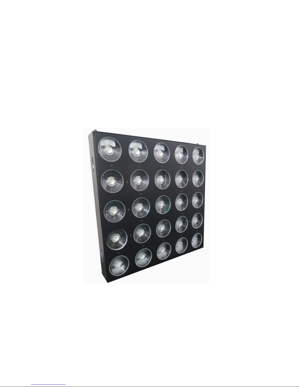
DESCRIPTION OF THE DEVICE
Features
> 8 or 80 channels DMX-512 .in optional
> Variable electronic strobe.
> Variable electronic dimmer (0-100%)
> LED operation menu with function buttons
> Reset to factory settings option.
> Build-in program with speed adjustment
> Matrix Control per each LEDs with RGB and mixing color
> Temperature sensor via software to control fans speed against overheat
INSTALLATION
Rigging
The installation of the projector has to be built and constructed in a way that it can hold 10 times the
weight for 1 hour without any harming deformation.
IMPORTANT!OVERHEAD RIGGING REQUIRES EXTENSIVE EXPERIENCE, including calculating
working load limits, installation material being used, and periodic safety inspection of all installation
material and the projector. If you lack these qualifications, do not attempt the installation yourself, but
instead use a professional structural rigger. Improper installation can result in bodily injury and or

4
damage to property. The projector had to be installed out of the reach of people
DANGER OF FIRE! When installing the device, make sure there is no highly-inflammable
material(decoration articles, etc.)within a distance of min.0.5m.
DMX 512 connection/ connection between fixture
The wires must not come into contact with each other, otherwise the fixture will not work at all or
properly. Please note the starting address depends upon which controller is being used. Only use a
DMX cable and 3-pin XLR-plugs and connectors in order to connect the controller with the fixture or one
fixture to another
Connection with the mains.
The earth has to be connected. The device must only be connected with an electric installation carried
out in compliance with IEC standards.
OPERATION
After you connected the effect to the mains, The fixture starts running
Stand Alone operation
In the stand alone mode, the fixture can be use without controller
Master/slave-operation
The master/slave-operation enables that several devices can be synchronized and controlled by one
master-device
DMX controlled operation
You can control the projectors individually via your DMX-controller
Addressing
The control board allows you to assign the DMX starting address,
Note;it’s necessary to insert the XLR termination plug (with 120ohm) in the last device in the link in order
to ensure proper transmission on the DMX data link.
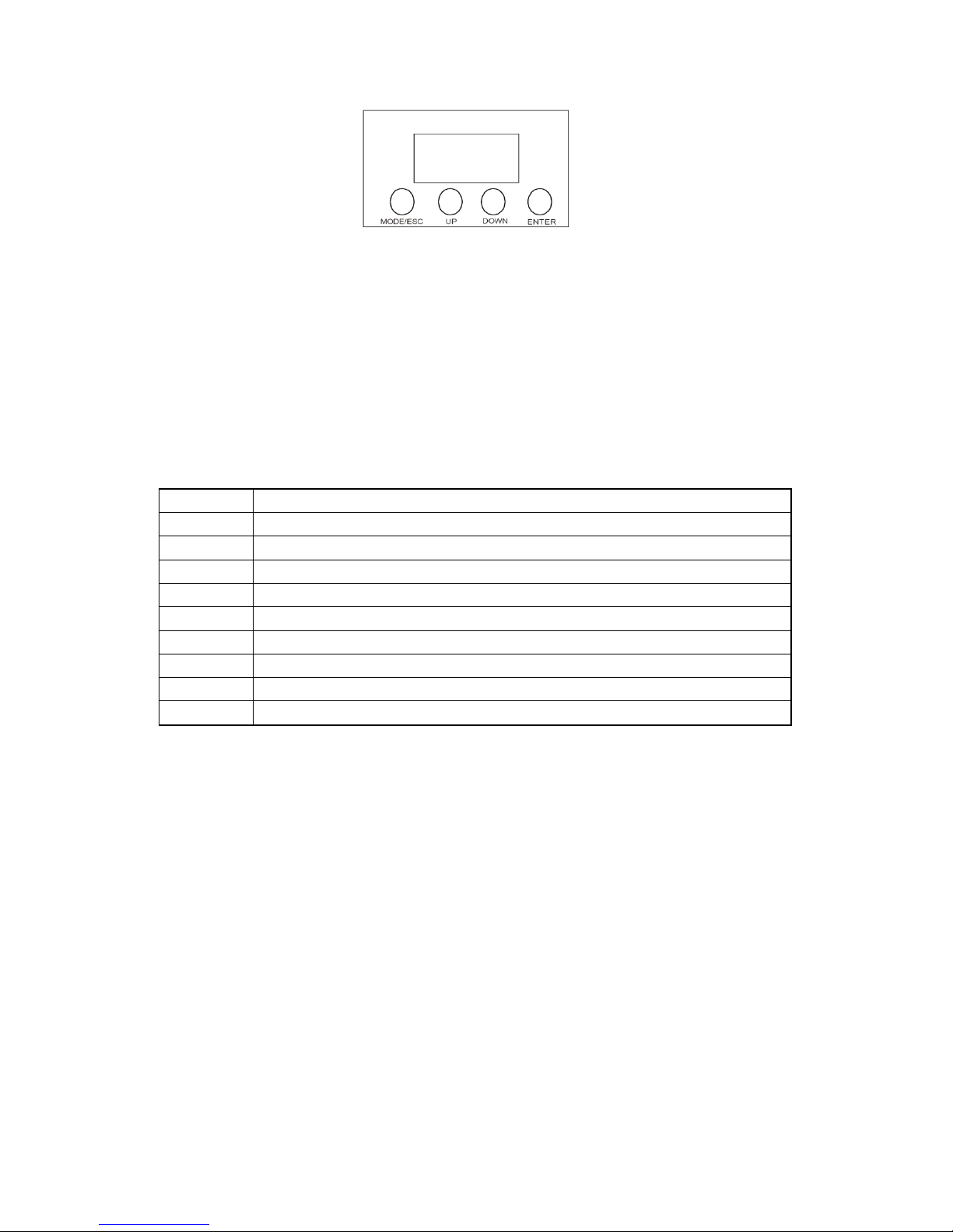
CONTRO L BOARD
The control board offer several features :you can simple set the starting address, run the
5
pre-programmed program or make a reset
he main menu is accessed by pressing the Mode/Esc-button, Browse through the submenu by pressing
Up or Down .Press the Enter-button in order to select the desired menu. You can change the selection
by pressing Up or Down, Confirm every selection by pressing the Enter-button. You can leave every
mode by pressing the Mode/Esc-button .The functions provided are described in the following setting.
MENU MAP
The device has two operation modes, It can be operated in Stand Alone or in DMX controlled
When in Master/Slave Synchronization Mode, only one in a series chain can be set as the master.
A001
8 DMX channel for setting address from 001~512
H001
20 DMX channel for setting address from 001~512
CC00
Color change 01~99 up or down to adjust the change speed
CP00
Color change in fade 01~99, up or down to adjust the change speed
DE00
Color change in pulse 01~99, up or down to adjust the change speed
FE00
Color change in matrix ,up or down to adjust the change speed
DEB1
Built matrix program with sound control 1
DEB2
Built matrix program with sound control 2
ID00
Set ID with more setting higher them DMX value
FROM
Slave setting
Note:output default setting address code is A001, pan is positive circumrotate 、tilt is positive
circumrotate、LED positively reveal.
Master/slave mode(auto-running、sound control)
This mode will allow you to link up 32 units together without a controller.
.Use standard DMX cables to daisy chain your units together via the DMX connector on the rear of
the units.Proper performance it may be necessary to use a terminator at the last fixture.
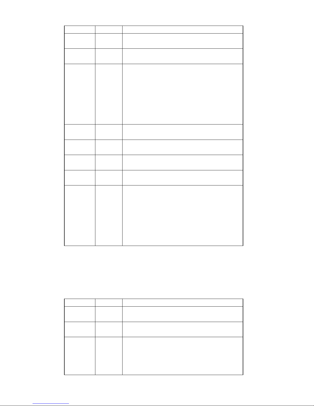
DMX-protocol
8 channel mode
6
Channel
Value
Function
1
0-255
Dimmer
0-100% dimmer
2
0-255
Strobe
Strobe from slowly to fast
3
0-20
21-70
71-120
121-170
171-220
221-240
241-255
Built-in Program
No function
Color change
Color change in fade
Color change in pulse
Matrix color change
Sound control mode 1
Sound control model 2
4
0-255
Speed
Control matrix effect speed from slowly to fast
5
0-255
Red
0-100% Red
6
0-255
Green
0-100% Green
7
0-255
Blue
0-100% Blue
8
0-4
5-9
10-14
15-19
20-24
25~255
ID setting
(control 50 fixture under same DMX ddress )
No function
ID1
ID2
ID3
ID4
ID5~ID50
80 channel mode
Channel
Value
Function
1
0-255
Dimmer
0-100% dimmer
2
0-255
Strobe
Strobe from slowly to fast
3
0-20
21-70
71-120
121-170
Built-in Program
No function
Color change
Color change in fade
Color change in pulse

7
171-220
221-240
241-255
Matrix color change
Sound control mode 1
Sound control model 2
4
0-255
Speed
Control matrix effect speed from slowly to fast
5
0-255
Red for LED 1
0-100% Red
6
0-255
Green for LED 1
0-100% Green
7
0-255
Blue for LED 1
0-100% Blue
8~79
0-255
Red/Green/Blue dimmer for LED 2 to LED 25
0~100% dimmer
80
0-4
5-9
10-14
15-19
20-24
25~255
ID setting
(control 50 fixture under same DMX ddress )
No function
ID1
ID2
ID3
ID4
ID5~ID50
TECHNICIAL SPECIFICATIONS
Model
C525 MATRIX COB WASH
Voltage
110V- 250V / 50-60Hz
Power consumption:
600w
LED
25pcs 30w RGB Tri COB LEDs
Gross Weight
20.5Kgs
Dimensions
580(H) x580(W) x200(L) mm
Table of contents
Other STSLITE Dj Equipment manuals


Popular Dj Equipment manuals by other brands


Chauvet Professional
Chauvet Professional GROUND SUPPORT 2 KIT user manual

Lightmen
Lightmen LITEBARPRO 12Q manual

MA lighting
MA lighting dot2 XL-B Quick manual

Sparktacular FX Machines
Sparktacular FX Machines SparkOne owner's manual

Elation
Elation FUZ567 user manual

Velleman
Velleman VDPLW2300N user manual