STSLITE M SPOT 200 User manual

M SPOT 200 LED MOVING HEAD
User Manual
Ver1.0

1
Table of contents
INTRODUCTION ……………………………………………….…………………………..2
SAFETY INSTRUCTIONS…………………………………………………………………2
OPERATING DETERMINATIONS…………………………………………….…………..2
DESCRIPTION OF THE DEVICE…………………………………………………………3
INSTALLATION………………………………………………………………….…………..4
OPERATION……………………………………………………………………….………...4
Stand alone operation…………………………………………………………….…………4
Master slave operation…………………………………………………………….……..…4
DMX controlled operation………………………………………………………….…….…4
Addressing…………………………………………………………………………….…..…4
Control board………………………………………………………………………….…..…4
DMX protocol………………………………………………………………………….…..…5
TECHNICAL SPECIFICATIONS…………………………………………………….……8

2
Every person involved with installation. operation and maintenance of this fixture has to
- be qualified
- follow the instruction of this manual
- consider this manual to be part of the total product
- Keep this manual for the entire service life of the product
- pass this manual to every future owner or use of the product
INTRODUCTION
Thank you for choosing our fixture, if you follow up the instruction given in this manual we be sure that
you will enjoy this product for a long period of time
SAFETY INSTRUCTION
This device has left our premises in absolutely perfect condition .In order to maintain this condition and
to ensure a safe operation, it is absolutely necessary for the user to follow the safety instruction and
warning notes written in this user manual.
Important: Damages caused by the disregard of this user manual are not subject o warranty, the dealer
will not accept liability for any resulting defects of problem. If the device had been exposed to drastic
temperature fluctuation (e.g. after transportation),do not switch it on immediately. The arising
condensation water might damage your device. Leave the device switched off until it had reached room
temperature. Please make sure that there are no obvious transport damages, should you notice any
damages on the AC connection cable or on the casing, do not take the device into operation and
immediately consult your local dealer.
OPERATING DETERMINATIONS
This device is designed for permanent operation. Consistent operation breaks will ensure that the
device will serve you for a long time without defects. Do not shake the device. Avoid brute force when
installing or operation the device. Never lift the fixture by holding it at the projector-head. As the
mechanics may be damaged. When choosing the installation-spot, please make sure that the device is
not exposed to extreme heat, moisture or dust. There should not be any cable lying around. Please
make sure that the fixture can not be touched or bumped. Your endanger your own and the safety of
CAUTION!
Be careful with your operations, With a dangerous voltage you can suffer a dangerous electric
shock when touching the wires.
CAUTION !
Keep this device away from rain and moisture
Unplug mains lead before opening the housing
For your own safety, please read this user manual carefully before you initially start-up
3
others.
DESCRIPTION OF THE DEVICE
Features
> High power 200w white led
>50000 hours lifetime and lower power consumption
> 17 DMX channel in optional
>540 degree PAN and 270 degree tilt movement
>1 Color wheel with 9 diachronic colors plus open
> 1 static gobo wheel with 9 gobos plus open.
> 1 rotated gobo wheel with 7 gobos plus open.
> Rotated prism with speed adjustable and variable direction
> Infinite electric focus with 2m range, and shutter with variable speed
> 0~100% linear dimmer and 1-18 times/sec high speed electronic strobe
> DMX512, master-slave and sound activated controllable and auto with 8 built-in programs
INSTALLATION
Rigging
The installation of the projector has to be built and constructed in a way that it can hold 10 times the
weight for 1 hour without any harming deformation.
IMPORTANT!OVERHEAD RIGGING REQUIRES EXTENSIVE EXPERIENCE, including calculating
working load limits, installation material being used, and periodic safety inspection of all installation
material and the projector. If you lack these qualifications, do not attempt the installation yourself, but
instead use a professional structural rigger. Improper installation can result in bodily injury and or
damage to property. The projector had to be installed out of the reach of people
DANGER OF FIRE! When installing the device, make sure there is no highly-inflammable
material(decoration articles, etc.)within a distance of min.0.5m.
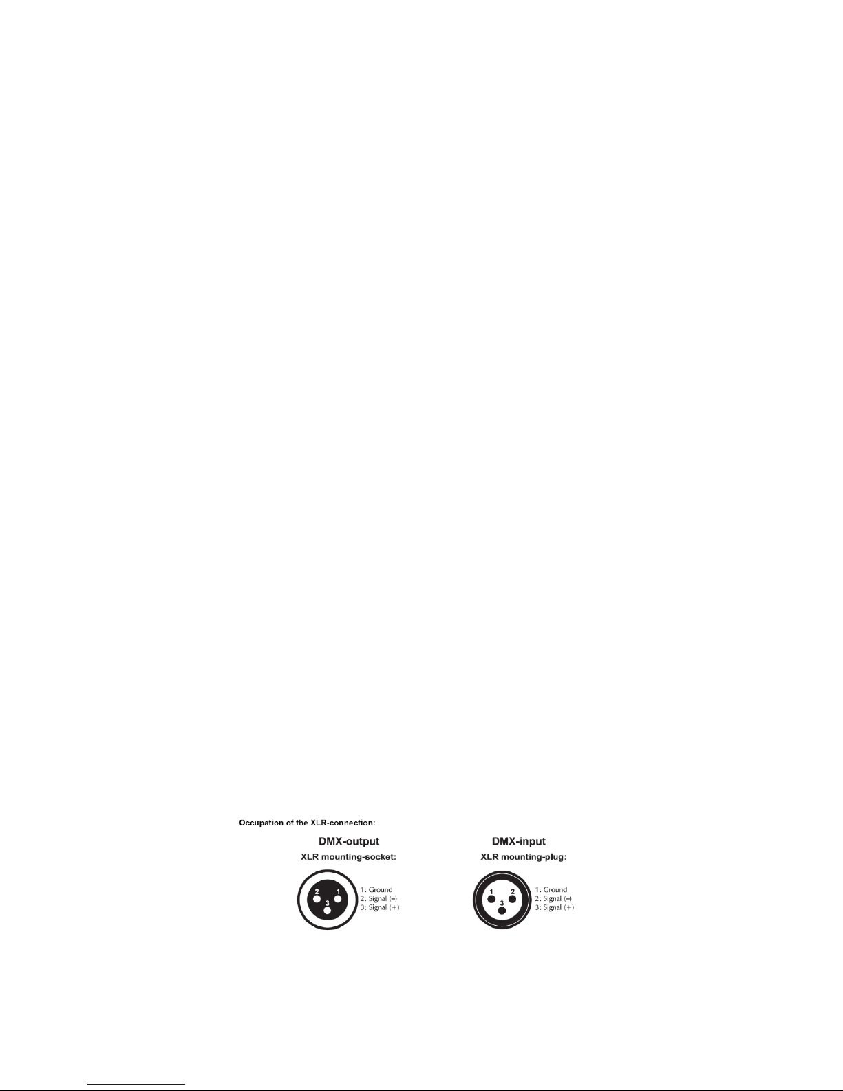
DMX 512 connection/ connection between fixture
The wires must not come into contact with each other, otherwise the fixture will not work at all or
properly. Please note the starting address depends upon which controller is being used. Only use a
DMX cable and 3-pin XLR-plugs and connectors in order to connect the controller with the fixture or one
fixture to another
Connection with the mains.

4
The earth has to be connected. The device must only be connected with an electric installation carried
out in compliance with IEC standards.
OPERATION
After you connected the effect to the mains, The fixture starts running
Stand Alone operation
In the stand alone mode, the fixture can be use without controller
Master/slave-operation
The master/slave-operation enables that several devices can be synchronized and controlled by one
master-device
DMX controlled operation
You can control the projectors individually via your DMX-controller
Addressing
The control board allows you to assign the DMX starting address,
Note;it’s necessary to insert the XLR termination plug (with 120ohm) in the last device in the link in order
to ensure proper transmission on the DMX data link.
CO NT RO L B O AR D
The control board offer several features :you can simple set the starting address, run the
pre-programmed program or make a reset
the main menu is accessed by pressing the Mode/Esc-button, Browse through the submenu by
pressing Up or Down .Press the Enter-button in order to select the desired menu. You can change the
selection by pressing Up or Down, Confirm every selection by pressing the Enter-button. You can leave
every mode by pressing the Mode/Esc-button .The functions provided are described in the following
setting.
M EN U M AP
The device has two operation modes, It can be operated in Stand Alone or in DMX controlled
SET ( Setting )
Run Mode
DMX,Auto 1 ,Auto 2,Random ,Sound
DMX-Address
001-512
Channel Mode
17 CH
Invert Pan
ON/OFF
Invert Tilt
ON/OFF ,
Pan-Tilt Swap
ON/OFF
Pan-Tilt Encoder
ON/OFF
No DMX Signal
KEEP/CLEAR
Linear color
ON/OFF
Load Default
OK/Cancel

5
Man(Manual)
Pan
0-255
Pan Fine
0-255
Tilt
0-255
Tilt Fine
0-255
P-T Speed
0-255
Strobe
0-255
Dimmer
0-255
Color Wheel
0-255
Gobo Wheel 1
0-255
Gobo Wheel 2
0-255
Gobo Wheel 2 Rotation
0-255
Focus
0-255
Zoom
0-255
Prism
0-255
Prism rotation
0-255
Frost
0-255
Reset
OK/Cancel
Sys ( System )
VER.
Reset
Sensor Monitor
System Errors
DMX Monitor
D M X- pr o to c ol
17 DMX channel mode
channel
value
function
1
Pan movement
0-255
Pan movement
2
Pan Fine
0-255
Pan fine movement
3
Tilt movement
0-255
Tilt movement
4
Tilt Fine
0-255
Tilt fine movement
5
0-255
Pan/Tilt Speed
Pan/Tilt movement with decreasing speed
6
Shutter/Strobe
0-3
Shutter close
4-251
Strobe with increasing speed
252-255
Shutter open

6
7
Dimmer
0-255
0~100% linear dimmer
8
Color wheel
0-4
White
5-9
White+Red
10-14
Red
15-19
Red+Green
20-24
Green
25-29
Green+Blue
30-34
Blue
35-39
Blue+Orange
40-44
Orange
45-49
Orange+Purple
50-54
Purple
55-59
Purple+Yellow
60-64
Yellow
65-69
Yellow+Light Green
70-74
Light Green
75-79
Light Green+Light Blue
80-84
Light Blue
85-89
Light Blue+Pink
90-94
Pink
95-99
Pink+White
100-182
Clockwise color change with decreasing speed
183-255
Anti-clockwise color change with increasing speed
9
Gobo Wheel 1
0-9
Open/White
10-19
Gobo 1
20-29
Gobo 2
30-39
Gobo 3
40-49
Gobo 4
50-59
Gobo 5
60-69
Gobo 6
70-79
Gobo 7
80-89
Gobo 8
90-99
Gobo 9
100-104
Gobo 1 shaking with increasing speed
105-109
Gobo 2 shaking with increasing speed
110-114
Gobo 3 shaking with increasing speed
115-119
Gobo 4 shaking with increasing speed
120-124
Gobo 5 shaking with increasing speed
125-129
Gobo 6 shaking with increasing speed
130-134
Gobo 7 shaking with increasing speed
135-139
Gobo 8 shaking with increasing speed
140-144
Gobo 9 shaking with increasing speed

7
145
White light gobo shaking
146-200
Anti-clockwise gobo change with decreasing speed
201-255
Clockwise gobo change with increasing speed
10
Gobo Wheel 2
0-9
White
10-19
Gobo 1
20-29
Gobo 2
30-39
Gobo 3
40-49
Gobo 4
50-59
Gobo 5
60-69
Gobo 6
70-79
Gobo 7
80-89
Gobo 1 shaking with increasing speed
90-99
Gobo 2 shaking with increasing speed
100-109
Gobo 3 shaking with increasing speed
110-119
Gobo 4 shaking with increasing speed
120-129
Gobo 5 shaking with increasing speed
130-139
Gobo 6 shaking with increasing speed
140-149
Gobo 7 shaking with increasing speed
150-200
Anti-clockwise gobo change with decreasing speed
201-255
Clockwise gobo change with increasing speed
11
Gobo Wheel 2 Rotation
0-127
Gobo angle adjustment
128-191
Clockwise gobo rotation with decreasing speed
192-255
Anti-clockwise gobo rotation with increasing speed
12
Focus
0-255
0~100% from far to near adjustment 0-100%
13
Zoom
0-255
Zoom in/out
14
Prism
0-127
No function
128-255
3-face Prism effect
15
Prism rotation
0-127
Prism angle adjustment
128-190
Rotated prism with decreasing speed in anti-clockwise
191-192
No function
193-255
Rotated prism with increasing speed in clockwise
16
Frost
0-127
No function
128-255
Frost effect
17
Reset
0-25
No function
26-76
Reset for Gobo/color/prism/rotated gobo/rotated
prism/focus/zoom/frost
77-127
Reset for pan/tilt
8
128-255
All reset
TECHNICIAL SPECIFICATIONS
Model
M SPOT 200 LED MOVING HEAD
Voltage
100V- 250V / 50/60Hz
Power consumption:
290W
LED
200w high power white led
Net Weight / Gross Weight
14.5Kgs / 16.8Kgs
Dimensions
44*41*54cm
Other manuals for M SPOT 200
1
Table of contents
Other STSLITE Dj Equipment manuals


