STT Emtec SCRmarine Instruction sheet

Document
STT SCRmarine
Installation Guideline
Date
2019-05-15
Page
1
Issue: 1.8
STT Emtec AB (pbl)
Box 46, Njurundavägen 16A
SE-862 02 NJURUNDA
SWEDEN
Tel: +46 (0)60
-
64 10 40
Fax: +46 (0)60 64 10 45
e-mail: info@sttemtec.com
Internet: www.sttemtec.com
Head office:
Njurunda
Org.nr: 55 62 05 – 2927
VAT ID: SE556205292701
ISO-cetrifikat nr: 15627
Installation Guideline
This guideline describes the recommended installation procedure and maintenance for the STT SCRmarine system
Latest version available at www.sttemtec.com
Document
STT SCRmarine
Installation Guideline
Date
2019-05-15
Page
2
Issue: 1.8
STT Emtec AB (pbl)
Box 46, Njurundavägen 16A
SE-862 02 NJURUNDA
SWEDEN
Tel: +46 (0)60
-
64 10 40
Fax: +46 (0)60 64 10 45
e-mail: info@sttemtec.com
Internet: www.sttemtec.com
Head office:
Njurunda
Org.nr: 55 62 05 – 2927
VAT ID: SE556205292701
ISO-cetrifikat nr: 15627
Table of content
1. Purpose
1.1. SCR technology
1.2. System overview
1.3. Components overview
1.4. System requirements
1.5. Commissioning requirements
2. Exhaust components installation
2.1. Flanges and gaskets
2.2. Thermal expansion
2.3. Insulation
2.4. Exhaust mixer and SCR chamber (SCR assembly)
2.4.1. Function
2.4.2. Installation
2.4.3. Maintenance
2.5. POC (Particle Oxidation Catalyst)
2.5.1. Function
2.5.2. Installation
2.5.3. Maintenance
3. DEF dosing components installation
3.1. General
3.2. Components placement
3.3. DEF supply lines
3.3.1. Function
3.3.2. Installation
3.3.3. Maintenance
3.4. DEF service tank
3.4.1. Function
3.4.2. Installation
3.4.3. Maintenance
3.4.4. Bulk tank
3.4.5. Tank heating
3.5. FR unit
3.5.1. Function
3.5.2. Installation
3.5.3. Maintenance
3.5.4. Adjusting the air pressure
3.5.5. Air compressor considerations
3.6. DEF supply pump
3.6.1. Function
3.6.2. Installation
3.6.3. Maintenance
3.7. DEF dosing unit
3.7.1. Function
3.7.2. Installation
3.7.3. Maintenance
3.7.4. Replacing the DEF filter
3.7.5. Replacing the DEF dosing unit

Document
STT SCRmarine
Installation Guideline
Date
2019-05-15
Page
3
Issue: 1.8
STT Emtec AB (pbl)
Box 46, Njurundavägen 16A
SE-862 02 NJURUNDA
SWEDEN
Tel: +46 (0)60
-
64 10 40
Fax: +46 (0)60 64 10 45
e-mail: info@sttemtec.com
Internet: www.sttemtec.com
Head office:
Njurunda
Org.nr: 55 62 05 – 2927
VAT ID: SE556205292701
ISO-cetrifikat nr: 15627
3.8. Injection nozzle
3.8.1. Function
3.8.2. Installation
3.8.3. Maintenance
3.8.4. Replacing the injection nozzle
4. Electrical components installation
4.1. Control cabinet
4.1.1. Function
4.1.2. Installation
4.1.3. Maintenance
4.2. NOx concentration sensor
4.2.1. Function
4.2.2. Installation
4.3. Exhaust temperature sensors
4.3.1. Function
4.3.2. Installation
4.4. Exhaust backpressure sensor
4.4.1. Function
4.4.2. Installation
4.4.3. Sensor relocation
4.5. Cables
4.5.1. Cable restrictions
4.5.2. Wire connection
4.5.3. Component layout
4.5.4. CAN databus
4.5.5. CAN termination
4.5.6. Activation relay input
4.5.7. Alarm relay output
4.5.8. Fuses and system disable
4.5.9. Cable shield
4.5.10.Power consumption
4.5.11.Discrete engine sensors
5. System operation
5.1. Routine operation
5.2. Enabling and disabling DEF dosing
5.3. Troubleshooting
5.4. Monitoring system
5.4.1. Control system operating states
5.4.2. LCD diagnose operation
5.4.3. Diagnose menus
5.4.4. Runtime data
5.4.5. Actuator test
5.4.6. Diagnostic trouble codes
5.4.7. “Normal” trouble codes
5.5. External diagnose options
5.5.1. Slave display panel
5.5.2. PC diagnose software

Document
STT SCRmarine
Installation Guideline
Date
2019-05-15
Page
4
Issue: 1.8
STT Emtec AB (pbl)
Box 46, Njurundavägen 16A
SE-862 02 NJURUNDA
SWEDEN
Tel: +46 (0)60
-
64 10 40
Fax: +46 (0)60 64 10 45
e-mail: info@sttemtec.com
Internet: www.sttemtec.com
Head office:
Njurunda
Org.nr: 55 62 05 – 2927
VAT ID: SE556205292701
ISO-cetrifikat nr: 15627
Appendix 01 Technical specifications
Appendix 02 Commissioning prerequisites
Appendix 03 Maintenance
Appendix 04 Engine CAN bus access points
Appendix 05 Post-installation inspection
Appendix 06 LCD diagnostics chart
Appendix 07 System process chart
Appendix 08 AdBlue®safety manual
Appendix 09 Sensors datasheet
Appendix 10 Electrical reference drawings
Appendix 11 Mechanical reference drawings
Appendix 12 Installing discrete engine sensors
Appendix 13 PC diagnose manual (EmtecDiag)
Appendix 14 Retrieving diagnose data

Document
STT SCRmarine
Installation Guideline
Date
2019-05-15
Page
5
Issue: 1.8
STT Emtec AB (pbl)
Box 46, Njurundavägen 16A
SE-862 02 NJURUNDA
SWEDEN
Tel: +46 (0)60
-
64 10 40
Fax: +46 (0)60 64 10 45
e-mail: info@sttemtec.com
Internet: www.sttemtec.com
Head office:
Njurunda
Org.nr: 55 62 05 – 2927
VAT ID: SE556205292701
ISO-cetrifikat nr: 15627
1 Purpose
The purpose of this document is to give sufficient information on how to install and
operate the key components of the SCRmarine system. The installation guideline also
describes the post adjustments and inspection processes and gives general information
on service and maintenance.
The first section gives an overview of the system and presents key points to enable
commissioning.
1.1 The SCR technology
NOx, nitrogen oxides, produced during the combustion process in diesel engines is a
contributing factor to air pollution. In an SCR system (Selective Catalytic Reduction) the
injected urea reacts over the catalyst with the harmful NOx gases in the exhaust and
converts it to water and nitrogen.
4NH3 + 4NO + O2→ 4N2+ 6H2O
Urea is a clear, non-toxic chemical. It is in normal conditions safe to handle and is not
harmful to the environment. To be able to inject the urea into the exhaust, a mixture of
urea diluted in distilled water, called Diesel Exhaust Fluid (DEF) is used. Another
technical name is Aqueous Urea Solution (AUS). Urea can cause corrosion to metal
parts; therefore the handling equipment must be designed to withstand urea. This applies
to tanks, pumps, lines, etc.
In this document the common names DEF and urea are used instead of trade
names.
It is important to only use DEF in accordance to the ISO 22241 or ISO
18611 standards.
Note! The fuel quality for the SCR system must fulfill EN 590.
Note! If a POC is used in combination with SCR or as a stand alone unit,
the fuel quality must fulfill EN 590.
For other fuel qualities please contact Stt Emtec AB for consultation.
Document
STT SCRmarine
Installation Guideline
Date
2019-05-15
Page
6
Issue: 1.8
STT Emtec AB (pbl)
Box 46, Njurundavägen 16A
SE-862 02 NJURUNDA
SWEDEN
Tel: +46 (0)60
-
64 10 40
Fax: +46 (0)60 64 10 45
e-mail: info@sttemtec.com
Internet: www.sttemtec.com
Head office:
Njurunda
Org.nr: 55 62 05 – 2927
VAT ID: SE556205292701
ISO-cetrifikat nr: 15627
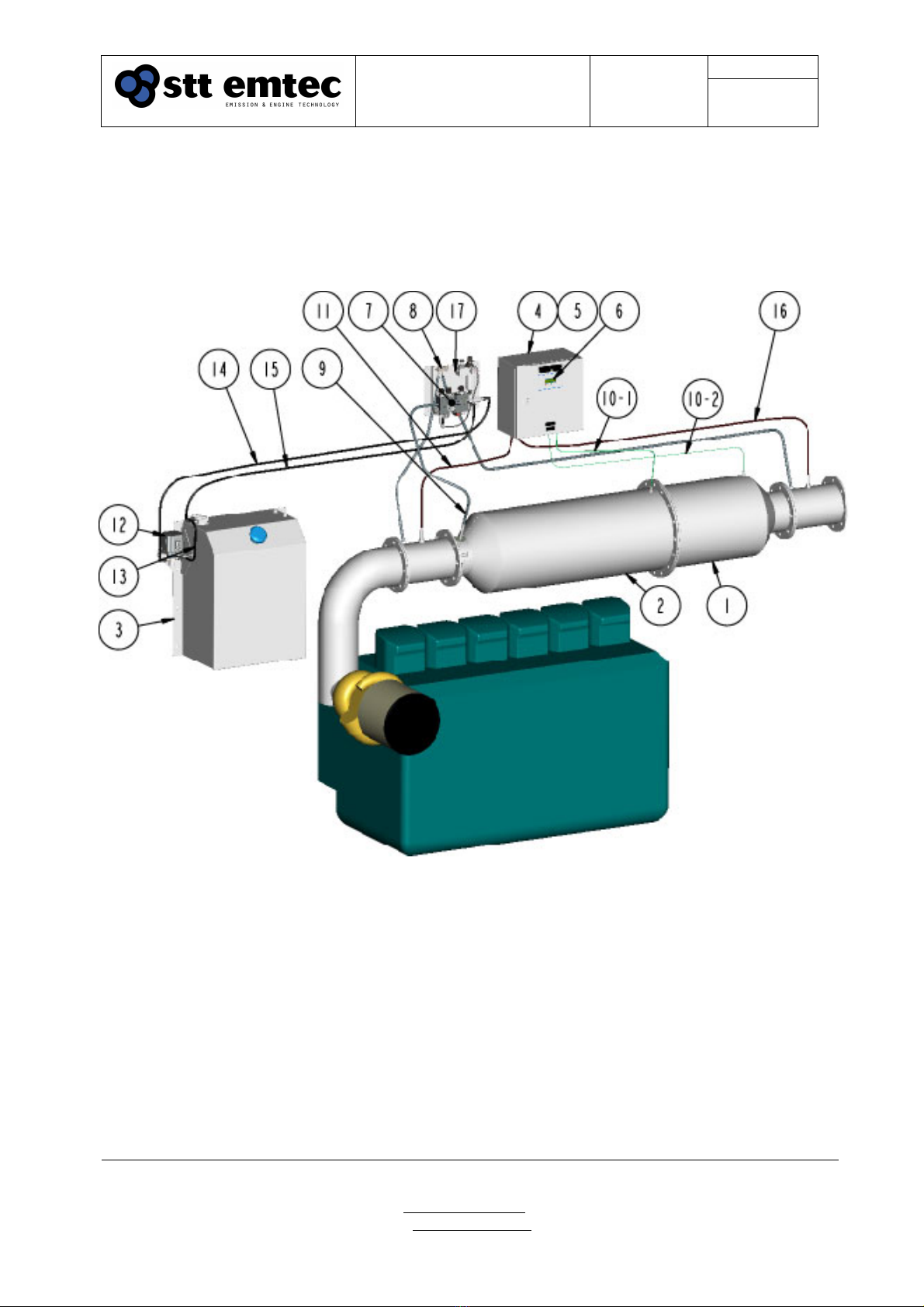
1.2 System overview
The schematic diagram in Figure 1 shows the layout of the SCRmarine system. It is a
fully automated after-treatment NOx reduction system with simple calibration and low
maintenance requirements.
Figure 1.
SCR marine system, arrangement and layout
1. SCR chamber, 2. Exhaust mixer, 3. DEF service tank, 4. Control cabinet, 5. Electronic Control Unit (ECU),
6. Diagnostic display, 7. DEF Dosing Unit (DDU)), 8. Exhaust pressure sensor, 9. Injection Nozzle,
10-1. SCR temperature sensor 1, 10-2. SCR temperature sensor 2, 11. NOx Sensor 1, 12. DEF supply pump,
13. DEF line; from service tank to supply pump, 14. DEF line; from supply pump to DDU,
15. DEF line; from DDU to service tank. 16. NOx sensor 2 (option), 17. FR unit (compressed air supply)
Document
STT SCRmarine
Installation Guideline
Date
2019-05-15
Page
7
Issue: 1.8
STT Emtec AB (pbl)
Box 46, Njurundavägen 16A
SE-862 02 NJURUNDA
SWEDEN
Tel: +46 (0)60
-
64 10 40
Fax: +46 (0)60 64 10 45
e-mail: info@sttemtec.com
Internet: www.sttemtec.com
Head office:
Njurunda
Org.nr: 55 62 05 – 2927
VAT ID: SE556205292701
ISO-cetrifikat nr: 15627
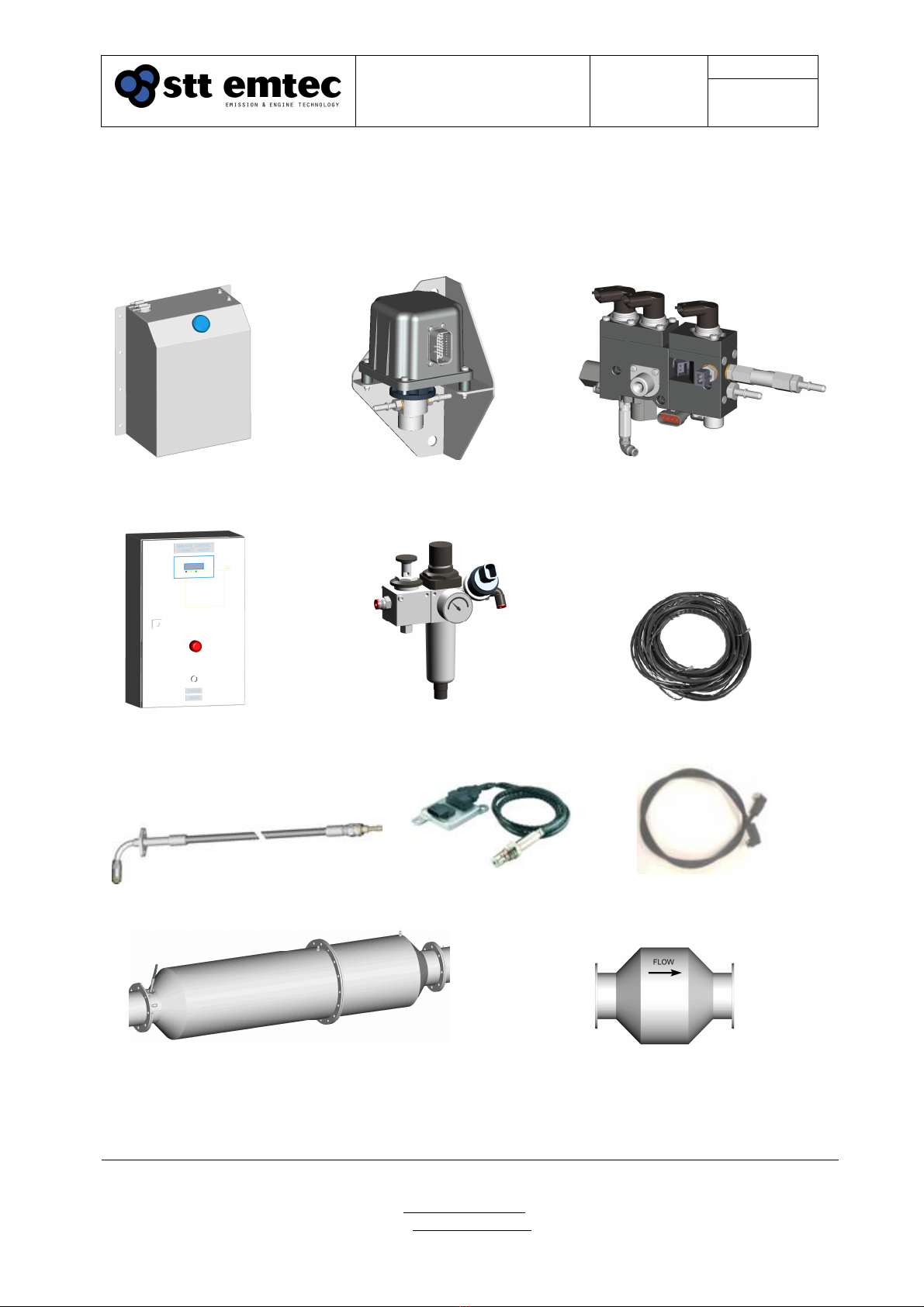
1.3 Components overview
The following are the key components of the SCRmarine system. Some parts are
optional, such as the POC (Particle Oxidation Catalyst). Appearance and contents can
vary between specific systems.
Figure 2.
SCR marine system, key components
DEF Service Tank
DEF Supply Pump
DEF Dosing Unit
FR Unit
Exhaust Mixer / SCR Chamber
Control Cabinet
Sensor Kit
Cable Kit
Injection Nozzle
Particle Oxidation Catalyst
(option)
Hose kit

Document
STT SCRmarine
Installation Guideline
Date
2019-05-15
Page
8
Issue: 1.8
STT Emtec AB (pbl)
Box 46, Njurundavägen 16A
SE-862 02 NJURUNDA
SWEDEN
Tel: +46 (0)60
-
64 10 40
Fax: +46 (0)60 64 10 45
e-mail: info@sttemtec.com
Internet: www.sttemtec.com
Head office:
Njurunda
Org.nr: 55 62 05 – 2927
VAT ID: SE556205292701
ISO-cetrifikat nr: 15627
1.4 System requirements
The SCRmarine is an automatic NOx reduction system. It is based upon a NOx sensor
measuring the actual emissions from the engine and therefore requires little or no
calibration during commissioning. An SCR catalyst assembly, and optionally a POC
(Particulate Oxidation Catalyst), is installed in the exhaust line as close to the engine as
possible to preserve exhaust temperature. Besides from the sensors relating to the SCR
assembly the SCRmarine requires the following from the vessel installation:
Power supply
24VDC or 230 VAC @ 150W nominal power
Power supply shall always be active to the control system
Compressed air supply
40 l/min FAD nominal while the engine is running
Min supply pressure 5 bar
An air tank of at least 50 l if air supply depends on engine running
Access to engine runtime data
The following signals need to available in runtime:
oEngine speed
oEngine load
oEngine boost air pressure
oEngine boost air temperature
oEngine running (ON/OFF) signal
The runtime signals can be obtained from the engines CAN (J1919) databus or
using discrete sensors
DEF
The reaction fluid for the SCR catalyst must always be available in the service
tank
As a rule of thumb the DEF consumption is ~ 5% of engine fuel consumption
1.5 Commissioning requirements
A checklist to enable system commissioning and to make sure that no vital details have
been overlooked is available in Appendix 02 - Commissioning prerequisites
In order to complete system commissioning an installation report must be completed and
returned to STT Emtec AB. The report document can be found in Appendix 05 – Post
installation check-up
Document
STT SCRmarine
Installation Guideline
Date
2019-05-15
Page
9
Issue: 1.8
STT Emtec AB (pbl)
Box 46, Njurundavägen 16A
SE-862 02 NJURUNDA
SWEDEN
Tel: +46 (0)60
-
64 10 40
Fax: +46 (0)60 64 10 45
e-mail: info@sttemtec.com
Internet: www.sttemtec.com
Head office:
Njurunda
Org.nr: 55 62 05 – 2927
VAT ID: SE556205292701
ISO-cetrifikat nr: 15627
2 Exhaust components installation
This section provides general and specific information on installing the mechanical
components in the exhaust system.
The exhaust system is stressed both by high temperature variations and vibrations. It is
therefore important to observe both the application notes in this document as well as
applying regulation according to the vessel requirements to ensure trouble free operation
of the SCRmarine system.
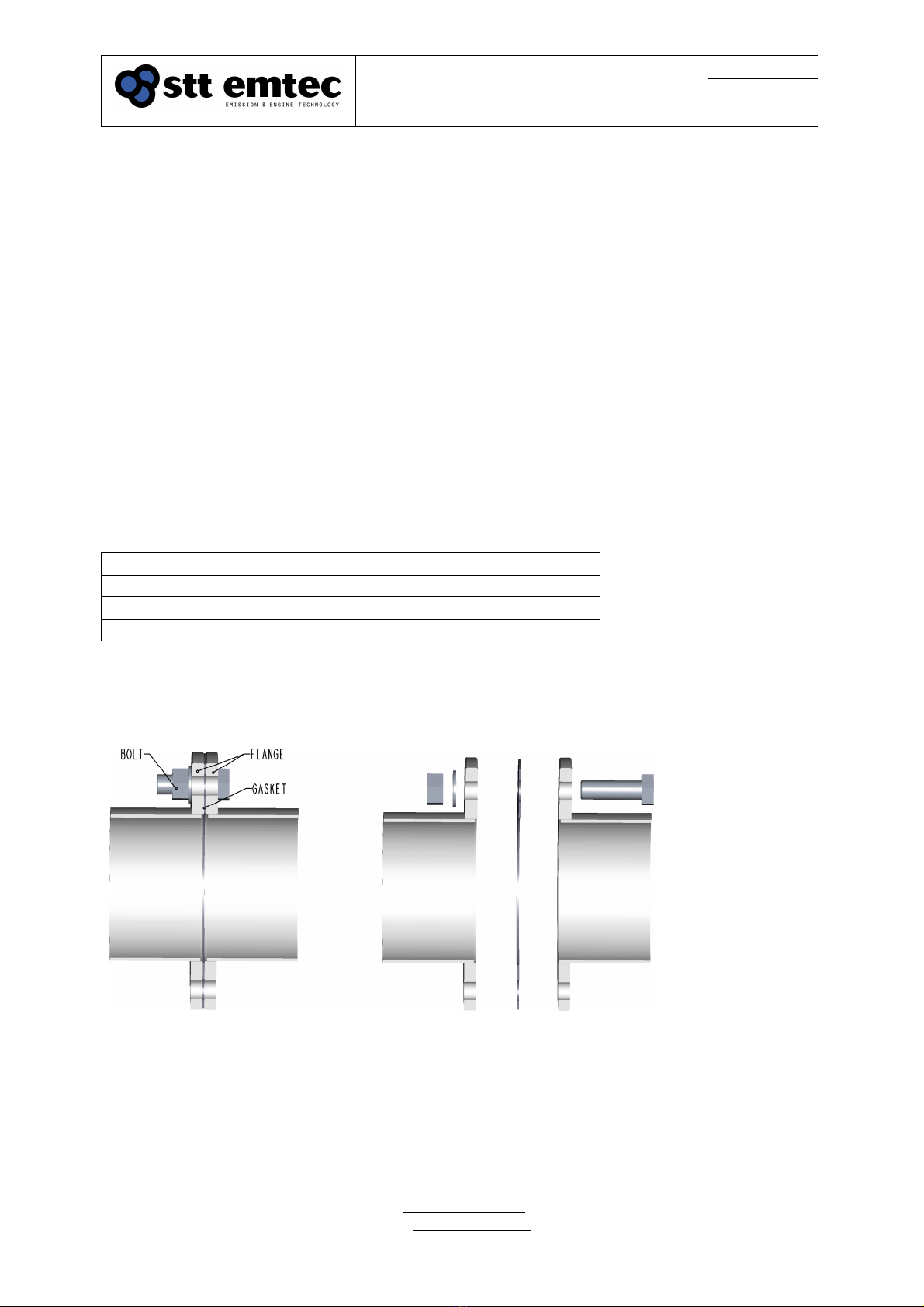
2.1 Flanges and gaskets
The canning of the exhaust components is produced of stainless steel with flanges on the
in- and outlet ports. The shape of the flanges can differ due to regulations and/or
customer demands. Please observe the type of flanges in the BOM for your SCRmarine
installation kit.
Table 1 Flange dimensions
Flange
Gasket part no
DN125 108665
DN150 109104
DN200 108893
Flanges are welded on the pipe ends. The flange pairs are mounted together with a
1.5mm stainless steel reinforced graphite gasket. For attachment, 8 - 16 pcs of zinc
plated screws (or stainless) M16x60 8.8 with nuts and washers are used.
Figure 3.
Flange pair, installed and exploded view

Document
STT SCRmarine
Installation Guideline
Date
2019-05-15
Page
10
Issue: 1.8
STT Emtec AB (pbl)
Box 46, Njurundavägen 16A
SE-862 02 NJURUNDA
SWEDEN
Tel: +46 (0)60
-
64 10 40
Fax: +46 (0)60 64 10 45
e-mail: info@sttemtec.com
Internet: www.sttemtec.com
Head office:
Njurunda
Org.nr: 55 62 05 – 2927
VAT ID: SE556205292701
ISO-cetrifikat nr: 15627
2.2 Thermal expansion
Relative movements and heat extension must always be considered when routing and
installing exhaust pipes. Use gastight flexible parts and compensators when necessary.
In general a heat expansion of 1-2 mm /meter piping for every 100°C can be used as a
rule of thumb.
2.3 Insulation
All exhaust components and the pipes leading from the engine need insulation. The
purpose of the insulation is to retain required operating exhaust temperature for the SCR
catalyst or POC at low load conditions and cold ambient temperatures. It is also
necessary to keep the surface temperature of the pipes and SCR mixer at a level where
condense is avoided. Insulation is also required to ensure the engine crew safety and
protection of the surrounding areas.
It is important to leave space for the insulation at the installation. In a typical installation
the insulation is minimum 50 mm thick. Additional insulation may be required according
to regulations and/or customer demands.
Document
STT SCRmarine
Installation Guideline
Date
2019-05-15
Page
11
Issue: 1.8
STT Emtec AB (pbl)
Box 46, Njurundavägen 16A
SE-862 02 NJURUNDA
SWEDEN
Tel: +46 (0)60
-
64 10 40
Fax: +46 (0)60 64 10 45
e-mail: info@sttemtec.com
Internet: www.sttemtec.com
Head office:
Njurunda
Org.nr: 55 62 05 – 2927
VAT ID: SE556205292701
ISO-cetrifikat nr: 15627
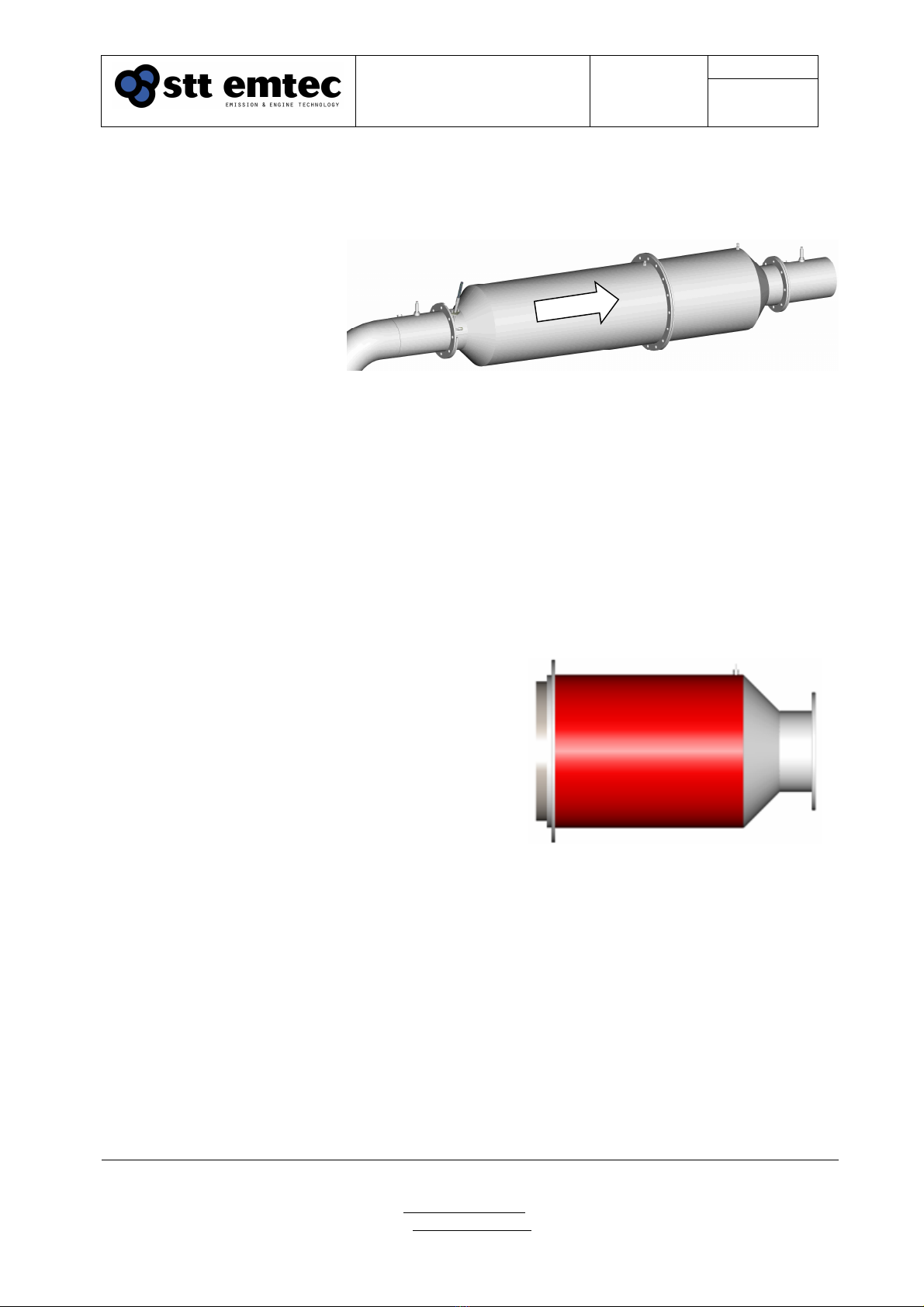
2.4 Exhaust mixer and SCR chamber (SCR assembly)
2.4.1 Function
In the SCR catalyst
chamber a chemical
reaction that converts NOx
and DEF into Nitrogen and
Water takes place. The
first part of the SCR
assembly is the exhaust
mixer which ensures that
the injected mixture of
DEF and air gets
thoroughly and
homogenously atomized before entering the catalyst chamber. The catalyst is only active
in temperatures above 220°C and it is therefore important that the whole SCR assembly,
and the pipes leading to it, are well insulated to preserve as much of the exhaust
temperature as possible, especially in low load and low ambient temperature conditions.
2.4.2 Installation
The SCR assembly can be installed in either vertical or horizontal position. The exhaust
mixer shall face the engine. The flange pairs are mounted with a 1.5mm stainless steel
reinforced graphite gasket, see section Flanges. It is important to leave space for the
insulation at the installation, see section
Insulation. Additional brackets to support the
catalyst assembly are required due to the weight
of the catalyst. The design of the support may be
depending on the surroundings and support of
other parts. STT Emtec recommends the use of
metal resilient elements type Vibratec® or
similar.
Welding is not allowed on the catalyst chamber
in the red area marked in figure 5. The catalyst
contains sliding parts for heat elongation
handling which can be damaged by welding.
2.4.3 Maintenance
The SCR is designed not to trap soot and therefore virtually maintenance free. It is
recommended to regularly check flanges for tightness and to verify the NOx converting
function of the catalyst. NOx conversion verification must be performed by trained
personnel only; please contact STT Emtec for more information. See also Appendix 03 –
Maintenance for further information
Exhaust
mixer
SCR
chamber
Exhaust flow
direction
Figure 4.
SCR assembly
Figure 5.
SCR chamber. The red area shows where
welding is not allowed.

Document
STT SCRmarine
Installation Guideline
Date
2019-05-15
Page
12
Issue: 1.8
STT Emtec AB (pbl)
Box 46, Njurundavägen 16A
SE-862 02 NJURUNDA
SWEDEN
Tel: +46 (0)60
-
64 10 40
Fax: +46 (0)60 64 10 45
e-mail: info@sttemtec.com
Internet: www.sttemtec.com
Head office:
Njurunda
Org.nr: 55 62 05 – 2927
VAT ID: SE556205292701
ISO-cetrifikat nr: 15627
2.5 POC (Particle Oxidation Catalyst)
2.5.1 Function
The POC is designed to trap soot and works with a
combination of wall-flow and partial flow to guarantee
trouble free engine operation without active
regenerations. The separated particles are reduced by
a continuous reaction with NO2.
The POC is an option and may not be included in all
SCRmarine systems.
2.5.2 Installation
The POC can be installed in either horizontal or vertical
position but must be installed as close as possible to
the turbocharger outlet. The POC shall be installed upstream of the Exhaust mixer and
SCR chamber. The POC and the exhaust pipe leading to it must be insulated in order to
preserve as much exhaust temperature as possible from the engine, but also to ensure
the engine crew safety and protection of the surrounding areas since the POC is typically
installed in the engine room.
The flange pairs are mounted with a 1.5mm stainless steel reinforced graphite gasket,
see section Flanges. It is important to leave space for the insulation at the installation,
see section Insulation.
Additional brackets to support the POC assembly may be needed depending on the
surroundings and support of other parts. STT Emtec recommends the use of metal
resilient elements type Vibratec® or similar. Additional insulation may be used according
to regulations and/or customer demands. It is important to leave space for the insulation
at the installation. In a typical installation the insulation is minimum 50 mm thick. Observe
the exhaust flow direction arrow on the POC.
Note! The flow direction arrow must be pointing
with the exhaust flow.
2.5.3 Maintenance
The POC is maintenance free but it is recommended to check for exhaust leaks at the
same time as the rest of the exhaust system, see Appendix 03 - Maintenance
Figure
6
.
(Picture from Emitec)
Exploded view of the POC
Figure 7.
Flow direction arrow on the POC
Document
STT SCRmarine
Installation Guideline
Date
2019-05-15
Page
13
Issue: 1.8
STT Emtec AB (pbl)
Box 46, Njurundavägen 16A
SE-862 02 NJURUNDA
SWEDEN
Tel: +46 (0)60
-
64 10 40
Fax: +46 (0)60 64 10 45
e-mail: info@sttemtec.com
Internet: www.sttemtec.com
Head office:
Njurunda
Org.nr: 55 62 05 – 2927
VAT ID: SE556205292701
ISO-cetrifikat nr: 15627
3 DEF dosing components installation
This section provides information on installing and maintaining the DEF dosing
components of the SCRmarine.
3.1 General
The dosing components are designed to carry liquid DEF from the service tank to the
exhaust stream. When dehydrated the DEF solution will form salt deposits from its Urea
content. This salt is prone to block the supply lines and the dosing components. The
following guidelines are intended to ensure that the system can evacuate DEF thoroughly
when injection is not required, i.e. when the engine is stopped, in order to avoid forming
deposits.
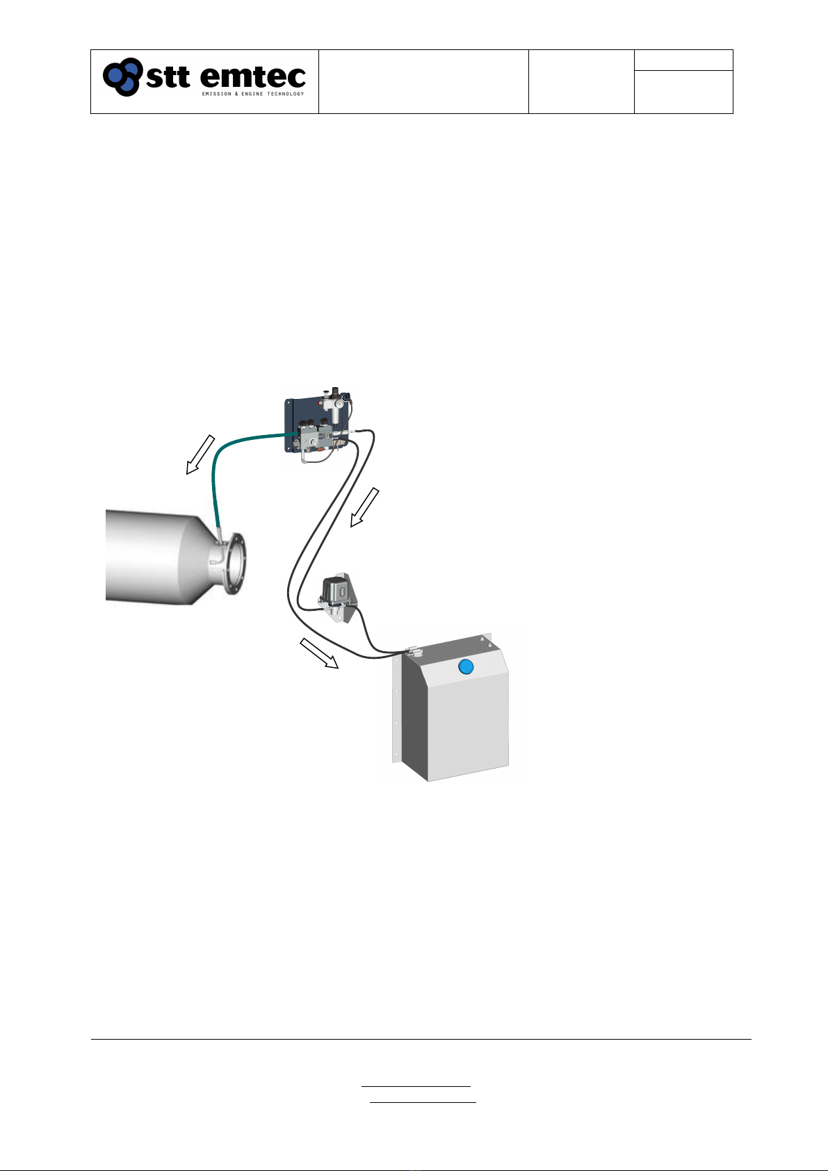
3.2 Components placement
When positioning the injection components it is important to consider their relative
positions in altitude. It is also important to maintain a constant slope of the pipes or hoses
carrying DEF and to avoid any air pockets.
These rules serve to accomplish a good evacuation of DEF from the injection
components
DDU above
mixer
DDU above
DEF supply
pump
DEF supply pump
above DEF
service tank (or
mounted on tank)
Figure 8.
Relative positioning of
injection components
Document
STT SCRmarine
Installation Guideline
Date
2019-05-15
Page
14
Issue: 1.8
STT Emtec AB (pbl)
Box 46, Njurundavägen 16A
SE-862 02 NJURUNDA
SWEDEN
Tel: +46 (0)60
-
64 10 40
Fax: +46 (0)60 64 10 45
e-mail: info@sttemtec.com
Internet: www.sttemtec.com
Head office:
Njurunda
Org.nr: 55 62 05 – 2927
VAT ID: SE556205292701
ISO-cetrifikat nr: 15627
3.3 DEF supply lines
3.3.1 Function
The DEF lines (Service tank - - Supply pump, Supply pump - - Dosing unit, Dosing unit - -
service tank) carry the DEF from the tank to the DEF dosing unit. The lines supplies in
the kit are made of polyamide (PA) or reinforced rubber with SAE quick lock fittings
matching those of the service tank, supply pump and DEF dosing unit. Other materials
requested must be supplied by installer and/or yard.
3.3.2 Installation
The DEF lines can be made either of stainless steel tubes, steel braided teflon hoses,
reinforced rubber hoses suitable for DEF or polyamide (PA) hoses. Depending on the
application, the connectors can be of compressed type (cone sealing) or SAE quick lock
type with O-ring sealing.
All DEF lines, suction- as well as pressure lines, have to be routed as straight as possible
to prevent air pockets which may have a negative impact on post injection drainage and
lead to freezing and other blockage. The inner diameter of hoses or pipes must be
minimum 4 mm and they must withstand a pressure of 20 bar.
Due to the volatility of the DEF; when using other lines than the supplies PA hoses, make
sure that all fittings are tight. Stainless steel compression fittings are very difficult to get
tight when carrying DEF.
Note! DEF is very volatile and will slip thru the slightest gap! Make sure all
connections are tight!
3.3.3 Maintenance
There supplied PA hoses are maintenance free.
Fittings are allocated according to the following table:
Table 2 DEF fittings
From
To
Fitting
DEF service tank DEF supply pump SAE 3/8”
DEF supply pump DEF dosing unit SAE 3/8”
DEF dosing unit DEF service tank SAE 5/16”
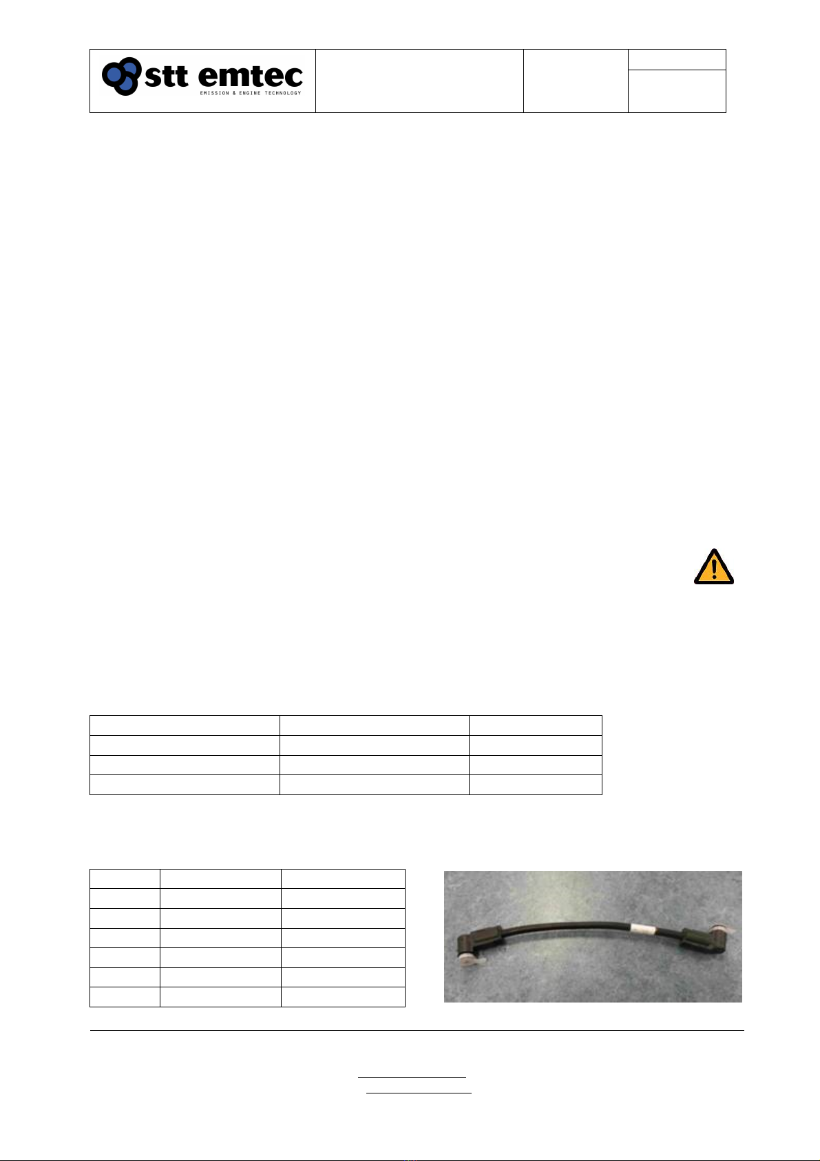
PA hoses with prefabricated fittings are available in the following lengths:
Table 3 DEF PA hoses part no
Length
SAE 3/8”
SAE 5/
16”
0.4 108744 108745
2 107462 107463
3 107997 107994
4 107998 107995
5 107999 107996
7 108344 108345
Figure
9
.
PA hose, 0.4m
Document
STT SCRmarine
Installation Guideline
Date
2019-05-15
Page
15
Issue: 1.8
STT Emtec AB (pbl)
Box 46, Njurundavägen 16A
SE-862 02 NJURUNDA
SWEDEN
Tel: +46 (0)60
-
64 10 40
Fax: +46 (0)60 64 10 45
e-mail: info@sttemtec.com
Internet: www.sttemtec.com
Head office:
Njurunda
Org.nr: 55 62 05 – 2927
VAT ID: SE556205292701
ISO-cetrifikat nr: 15627
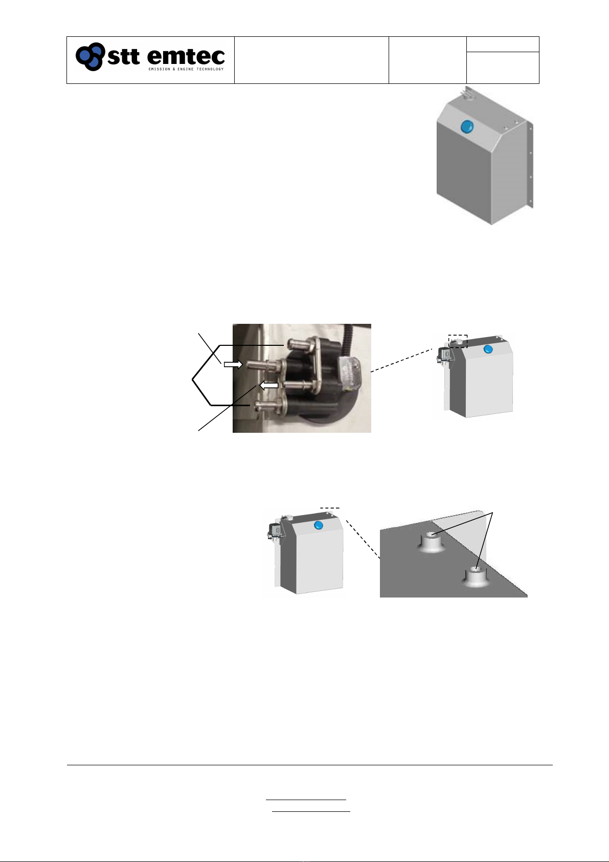
3.4 DEF service tank
3.4.1 Function
The service tank provides the DEF dosing unit with AdBlue®.
The liquid is pumped from the tank by using the DEF supply
pump normally mounted on the side of the tank. A built-in level
sensor is used by the control system to indicate refill on the
system display. The service tank has a filling cap for manual
filling and the cap is ventilated.
3.4.2 Installation
The DEF service tank can be mounted on additional brackets and has to be attached
firmly. The service tank connects to the DEF supply pump (suction line) and to the DEF
dosing unit (pressure line) thru nipples at the tank top.
3.4.3 Bulk tank
The tank also has two spare
bosses (M12x1.5) to the right at
the top of the tank suitable for
automatic refill from a bulk tank.
One of the connections should
be used to vent the service tank
to atmosphere during filling. If a
bulk DEF tank is located in the
vessel and the service tank is
permanently connected by a line
or hose, there must be a mechanical shut-off valve before the service tank. This is in
order to prevent hydraulic lock of the engine, in case of a DEF pump breakdown.
The bulk tank and service tank refill system is not within STT Emtecs scope of supply.
An automated service tank refill system should implement a high level alarm.
The recommended material selection for a bulk tank is chromium nickel or chromium
nickel molybdenum steel. Note that no forms of copper alloy are allowed.
SAE 3/8” DEF return line
from DEF dosing unit
SAE 3/8” DEF suction line
to DEF supply pump
Figure
11
.
Nipples for DEF and coolant water circulation
Engine coolant water
circulation for cold
environment operation
Figure 10.
DEF service tank.
Figure 12.
Bosses for automatic filling
Bosses for
automatic
service tank
filling
Document
STT SCRmarine
Installation Guideline
Date
2019-05-15
Page
16
Issue: 1.8
STT Emtec AB (pbl)
Box 46, Njurundavägen 16A
SE-862 02 NJURUNDA
SWEDEN
Tel: +46 (0)60
-
64 10 40
Fax: +46 (0)60 64 10 45
e-mail: info@sttemtec.com
Internet: www.sttemtec.com
Head office:
Njurunda
Org.nr: 55 62 05 – 2927
VAT ID: SE556205292701
ISO-cetrifikat nr: 15627
3.4.4 Tank heating
If tank heating is required in a cold environment an autonomous temperature control
circuit must be implemented. Circulating high temperatures, such as 80+°C engine
coolant, water thru the tank will degrade the DEF solution.
The tank heating system is not within STT Emtecs scope of supply.
Table 4 DEF service tank part no
Detail
Part no
DEF service tank 100L 107598
The 100 liter tank is sufficient for at least 70 hours of normal operation on a 300 kW
engine. Different tank sizes are available upon request.
3.4.5 Maintenance
The mesh filter under the filling cap should be observed during filling.
The mesh filter in the bottom of the tank (fitted on the armature) should be checked, and
cleaned if necessary,
Note! Prevent DEF from getting in contact with the air line or its
connections. Any air equipment that has been polluted with DEF has to
be replaced. DEF liquid or crystals in the air inlet can cause blockage
and damage to the DEF dosing unit!
Document
STT SCRmarine
Installation Guideline
Date
2019-05-15
Page
17
Issue: 1.8
STT Emtec AB (pbl)
Box 46, Njurundavägen 16A
SE-862 02 NJURUNDA
SWEDEN
Tel: +46 (0)60
-
64 10 40
Fax: +46 (0)60 64 10 45
e-mail: info@sttemtec.com
Internet: www.sttemtec.com
Head office:
Njurunda
Org.nr: 55 62 05 – 2927
VAT ID: SE556205292701
ISO-cetrifikat nr: 15627
1
2
3
5
4
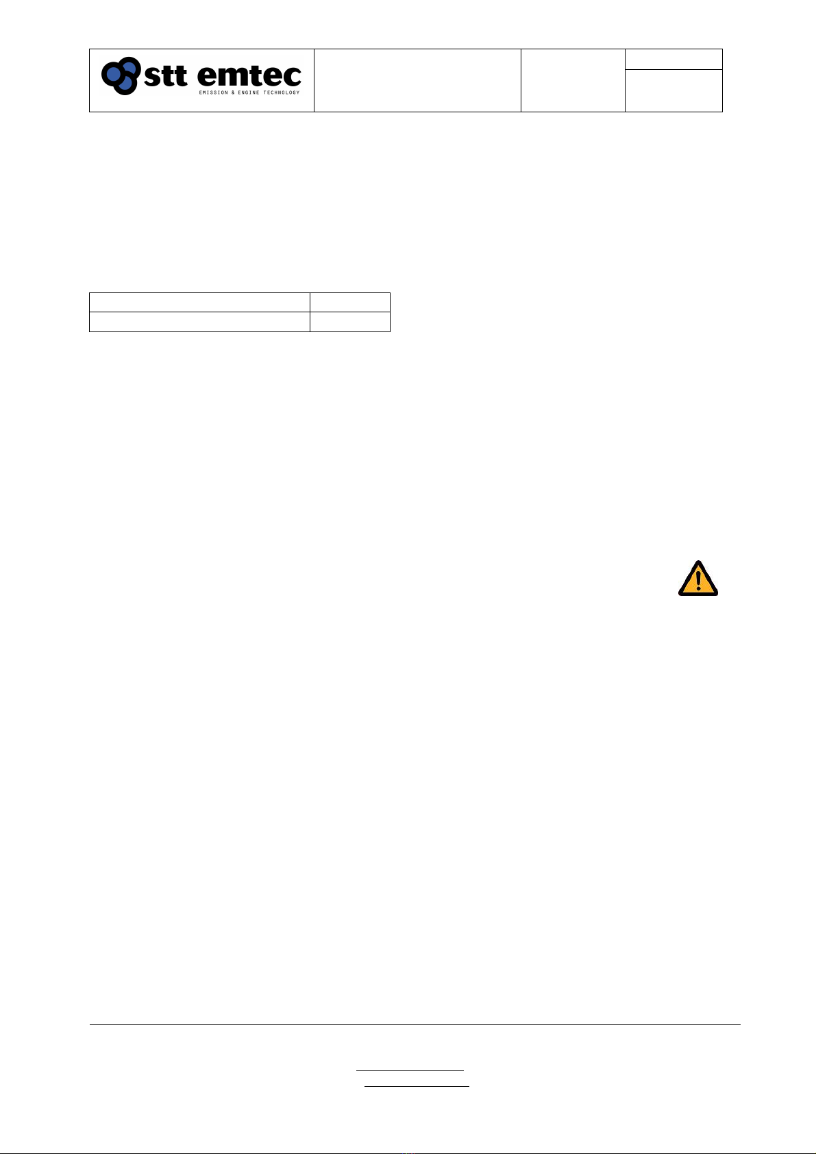
Air inlet from
external
compressor
Air outlet to
DEF dosing
unit
Figure 13. FR unit
1. Shut-off valve, 2. Pressure regulator, 3. Pressure switch,
4. Pressure gauge, 5. Condensate trap
3.5 FR unit
3.5.1 Function
The FR unit consists out of a
shut-off switch, a pressure
regulator with gauge, an
electronic pressure switch and a
condensate trap. The purpose of
the unit is to supply regulated air
pressure of 4.5 bar to the DEF
dosing unit. The pressure switch
fitted on the air outlet side is used
by the control system to indicate
air supply failure. The shut-off
switch on the FR unit should
always be open unless for safety
or maintenance purposes. If the
air supply needs to be shut off
always first shutdown the DDS by
releasing the Disabling switch
(right side fuse) in the control
cabinet and then wait for the
system display to read System OFF.
See section 5.2 Enabling and disabling.
Table 5 FR unit, part no
Detail
Part no
FR unit assembly 109105
3.5.2 Installation
The FR unit is connected to the vessel air pressure or an additional air compressor and
to the DEF dosing unit. Connections are typically made using Ø6mm PA hose but other
materials, such as stainless steel, may be required due to regulations.
The FR unit is normally located on the same mounting bracket as the DEF dosing unit
but may be relocated for space reasons. The unit comes assembled with Ø6 mm pneu-fit
quick release fittings on both inlet and outlet ports. The thread of the fittings is G1/4”
internal.
3.5.3 Maintenance
Check the condensate trap
Note! Do not attempt to disable the DDS by shutting off the air supply!
Blockage or damage to the injection components may occur!
See section Operating procedures – System shutdown.
Document
STT SCRmarine
Installation Guideline
Date
2019-05-15
Page
18
Issue: 1.8
STT Emtec AB (pbl)
Box 46, Njurundavägen 16A
SE-862 02 NJURUNDA
SWEDEN
Tel: +46 (0)60
-
64 10 40
Fax: +46 (0)60 64 10 45
e-mail: info@sttemtec.com
Internet: www.sttemtec.com
Head office:
Njurunda
Org.nr: 55 62 05 – 2927
VAT ID: SE556205292701
ISO-cetrifikat nr: 15627
1
3
4
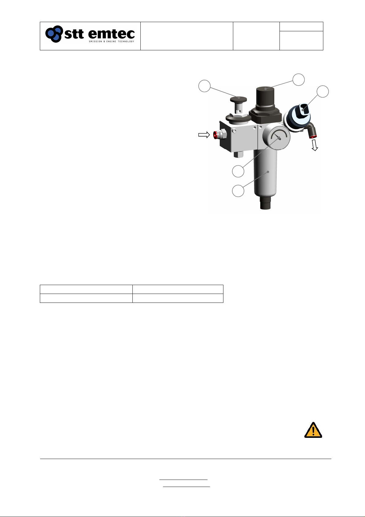
Figure 14.
FR unit
Spare parts
Table 6 FR unit, spare parts
Pos
Detail
Part no
1 Air regulator 107357
2 Gauge/manometer 108859
3 Pressure switch 108984
Document
STT SCRmarine
Installation Guideline
Date
2019-05-15
Page
19
Issue: 1.8
STT Emtec AB (pbl)
Box 46, Njurundavägen 16A
SE-862 02 NJURUNDA
SWEDEN
Tel: +46 (0)60
-
64 10 40
Fax: +46 (0)60 64 10 45
e-mail: info@sttemtec.com
Internet: www.sttemtec.com
Head office:
Njurunda
Org.nr: 55 62 05 – 2927
VAT ID: SE556205292701
ISO-cetrifikat nr: 15627
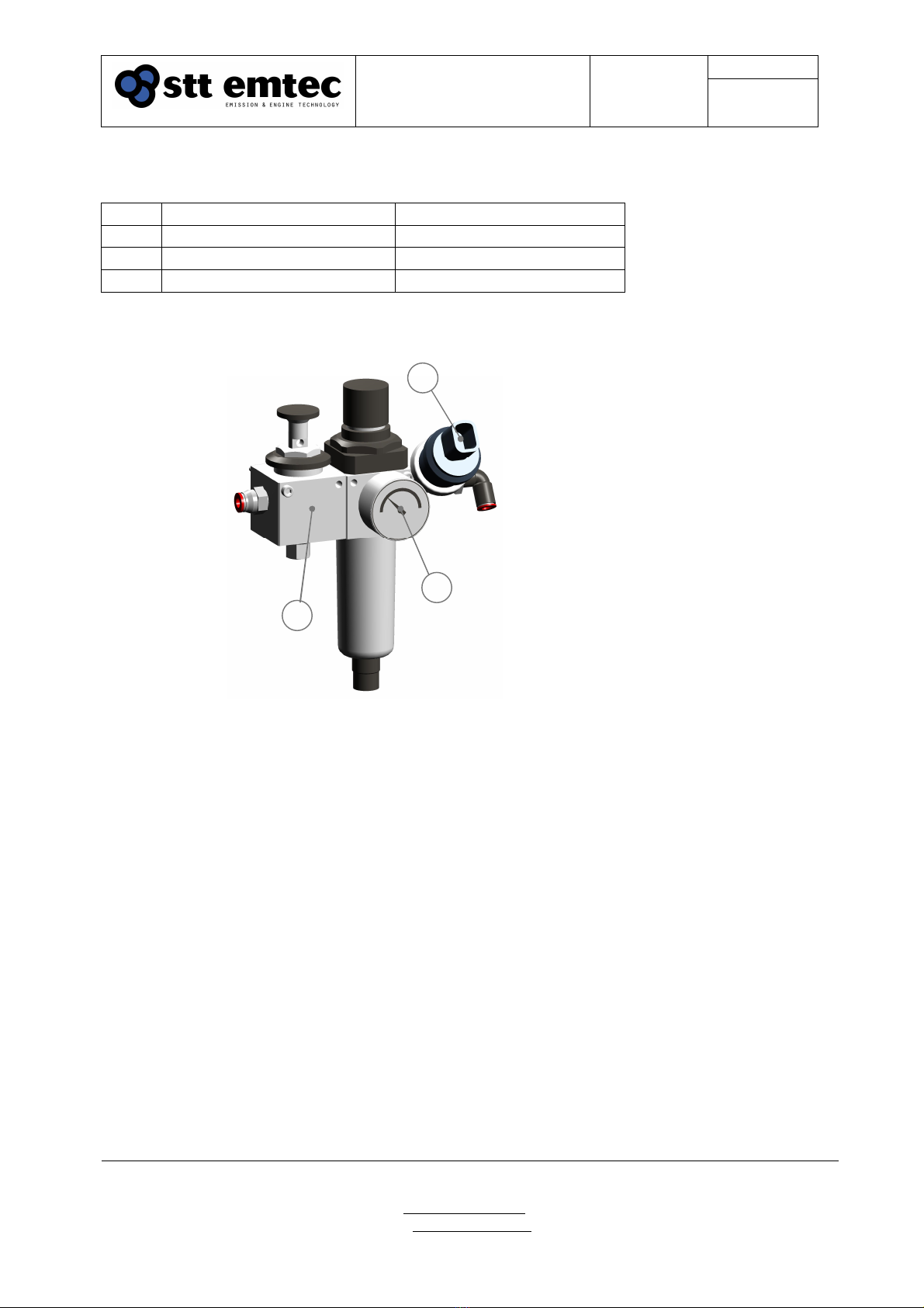
3.5.4 Adjusting the air pressure
The air pressure regulator is located on the right hand side
of the FR-unit. Max allowed inlet pressure is 16 bar and has
to be adjusted to 4.5±0.2 bar. Use the manometer on the
FR-unit when adjusting the air pressure.
Use the Diagnostic display, see section 5.4, to verify the
main air pressure;
1. Stop the engine
2. Go to the Actuator test page (Main page ↓ Key down)
3. Step to the AIR test (→Key right)
4. Activate the Atomization air valve (↓ Key down)
5. ‘Nozzle prs’ shall read 1600±200 mbar when correct
air pressure is adjusted
Note: The ‘Nozzle prs’ indicates the backpressure in the
injection nozzle resulting from the air flow thru the DEF dosing unit. This pressure level
should not be confused with the gauge reading of the pressure on the FR unit!
3.5.5 Air compressor considerations
Compressed air should be provided from the vessel air supply with installed oil separator.
If the compressed air supply includes an air dryer, then if possible, take the air supply to
the urea pump before the air dryer. If a compressed air system is not available a
separate air compressor has to be installed. Table 7 below contains STT Emtec’s
recommendations for the air compressor.
Table 7: Compressor data recommendations
Air consumption 40 l/min FAD
80 l/min peak (at flush)
Regulated pressure 4,5±0,2
Bar (gauge pressure)
Recommended
compressor capacity 290 l/min FAD
8-10 bar capacity
Screw compressors are
recommended
Tank volume Min 90 l to reduce the
compressor load time
When using a compressor driven by the engine, either by direct (e.g. belt-) drive or when
the engine supplies electrical power to the compressor, the same capacity requirements
as above regarding the compressor are recommended. However when the engine stops
so does the compressor and in this case the tank volume must be sufficient to handle
post-operation component cleaning.
Minimum tank volume depends on the pressure according to the following calculation:
Tank volume= 180/(pressure-4.5) liters (pressure expressed in bar)
Adjust to:
4.5 bar
gauge
Figure 15
FR unit
Note!
Piston type
compressors are
typically not designed for
continuous operation and
power capacity and tank size
must be selected with this in
mind.

Document
STT SCRmarine
Installation Guideline
Date
2019-05-15
Page
20
Issue: 1.8
STT Emtec AB (pbl)
Box 46, Njurundavägen 16A
SE-862 02 NJURUNDA
SWEDEN
Tel: +46 (0)60
-
64 10 40
Fax: +46 (0)60 64 10 45
e-mail: info@sttemtec.com
Internet: www.sttemtec.com
Head office:
Njurunda
Org.nr: 55 62 05 – 2927
VAT ID: SE556205292701
ISO-cetrifikat nr: 15627
3.6 DEF supply pump
3.6.1 Function
The DEF supply pump delivers pressurized DEF liquid to the
DEF dosing unit. Liquid that is not metered by the DDU is
returned to the service tank. The supply pump is speed- and
direction controlled by the ECU in the control cabinet. During
post injection the pump is reversed to assist in the evacuation
of the injection lines.
3.6.2 Installation
The preferred mounting position of the DEF supply pump is on
the left side of the DEF service tank near the tank fittings. The
pump bracket is designed to match the mounting holes of the
service tank. Should this location not be suitable the DEF supply
pump can be positioned within 0.2 metres below (equals max
DEF filling level) to 1.0 metres above the service tank top, see
figures 17-19. The low position restriction is to prevent drainage
of the tank and the high position limit is to ensure priming of the
supply pump under all conditions, Maximum length of the suction
line from the service tank to the supply pump is 2 metres.
The supply pump connects to the service tank and to the dosing
unit according to Figure 16.
3.6.3 Maintenance
The DEF supply pump is maintenance free
Table 8 DEF supply pump, part no
Detail
Part no
DEF supply pump 108918
Figure 17
Default (and lowest) DEF supply
pump mounting position
Figure 19
Mounting the DEF supply pump
below default position is not ok!
DEF pressure
line to dosing
unit
DEF suction
line from
service tank
Figure 16
DEF supply pump interface
Figure 18
Max elevation of DEF
supply pump
Max 1.0 m
above tank
top
Other manuals for SCRmarine
1
Table of contents
Popular Service Equipment manuals by other brands


Sealey
Sealey AK462DX.V2 quick start guide

Motorvac
Motorvac CARBONCLEAN MCS 245 Operator's manual

Chicago Pneumatic
Chicago Pneumatic CP87700 Operator's manual

Tektino
Tektino RCC-9A Maintenance manual

Selecta
Selecta DIESELPAK 300 instruction manual

Schumacher Electric
Schumacher Electric DSR PROSERIES DSR136 owner's manual